Otto Bock Skippi Plus Service Manual
Hide thumbs
Also See for Skippi Plus:
- Instructions for use manual (94 pages) ,
- Instructions for use manual (112 pages)
Table of Contents
Advertisement
Quick Links
Advertisement
Table of Contents

Related Manuals for Otto Bock Skippi Plus


Summary of Contents for Otto Bock Skippi Plus
- Page 1 Skippi Plus Service Manual...
-
Page 3: Table Of Contents
Skippi Plus power wheelchair service manual Page Contents 1 General information ......................5 1.1 Preface ........................5 1.2 Overview .........................6 2 Safety instructions ......................7 2.1 Explanation of symbols ..................7 2.2 Standards and directives ..................7 2.3 General safety instructions ..................7 2.4 Safety instructions for the use of tools and accessories ........8 2.5 Safety instructions for maintenance work .............9... - Page 4 8.5.1 Handheld programming device ................55 8.5.2 PC programming station (PCPS) ................57 8.6 Programmable parameters ..................57 8.6.1 Main parameters ......................57 8.6.2 “Drive” parameter settings ..................60 8.6.3 “Joystick” parameter settings ..................65 9 Übergabe ........................66 9.1 Endkontrolle ......................66 9.2 Übergabeprotokoll ....................67 10 Maintenance schedule ....................68 4 | Ottobock Skippi Plus...
-
Page 5: General Information
Please use these documents together. • Use the maintenance schedule (checklist) as a template for making copies. Retain com- pleted maintenance schedules and provide the customer with a copy. Instructions for use Skippi Plus 647G646=* Skippi Plus Ottobock | 5... -
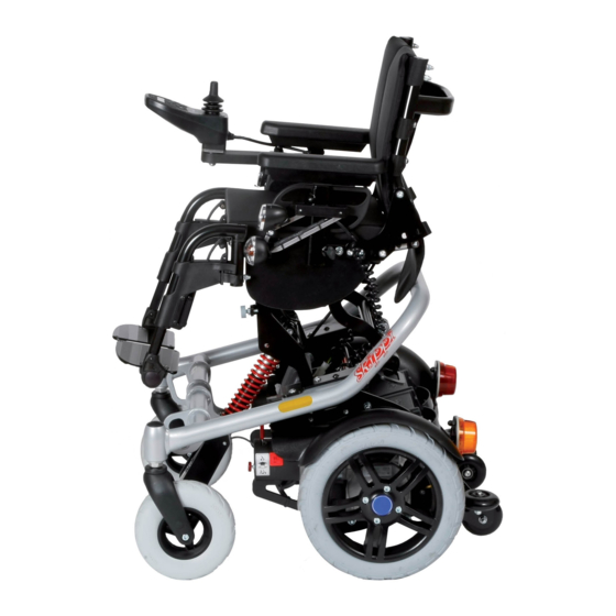
Page 6: Overview
General information 1.2 Overview Fig. 1 Overview 1 Standard back 6 Caster wheel 2 Side panel 7 Motor 3 Standard seat 8 Drive wheel 4 Brake lever 9 Frame 5 Footrest 10 Control panel 6 | Ottobock Skippi Plus... -
Page 7: Safety Instructions
Risk of damage caused by not adhering to maintenance intervals. The manufacturer recom- mends having the power wheelchair inspected and maintained for functionality and operational safe- ty by authorised, qualified personnel once a year. In case of frequent user changes (growing children or youths) or users with changing clinical pictures, the wheelchair should be inspected, adjusted and maintained twice a year. Skippi Plus Ottobock | 7... -
Page 8: Safety Instructions For The Use Of Tools And Accessories
CAUTION Risk due to hazardous materials. Hazardous materials may only be kept at the place of work in quantities required for ongoing tasks. Regularly and safely remove waste and residue. Clean up spilled substances immediately. 8 | Ottobock Skippi Plus... -
Page 9: Safety Instructions For Maintenance Work
Check the driving behaviour of the power wheelchair after cleaning it. INFORMATION The tyres of the power wheelchair contain chemical substances that may react with other chemical substances (e.g. cleaning agents, acids, etc.). Skippi Plus Ottobock | 9... -
Page 10: Safety Instructions For Maintenance Work On Electrical Components
2.7.1 General information on electromagnetic interference Power wheelchairs may be susceptible to electromagnetic interference (EMI), which is inter- fering electromagnetic energy (EM) emitted from sources such as radio stations, TV stations, amateur radio (HAM) transmitters, two-way radios, and cellular phones. 10 | Ottobock Skippi Plus... -
Page 11: Warnings Regarding Effects Of Electromagnetic Interference
TV stations, amateur radio (HAM) transmitters, two-way radios, and cellular phones can affect power wheelchairs and motorized scooters. Following the warnings listed below should reduce the chance of unintended brake release or power wheelchair movement which could result in serious injury. Skippi Plus Ottobock | 11... -
Page 12: Interference Resistance Of This Power Wheelchair
INFORMATION 20 volts per meter (V/m) is a generally achievable and effective immunity level against interference from radio wave sources (as of May 1994) (the higher the level, the greater the protection); INFORMATION This power wheelchair model as shipped, with no further modification, has an immunity level of 20 V/m. 12 | Ottobock Skippi Plus... -
Page 13: Safety Instructions For Disposal
Before transporting the power wheelchair, switch off the control unit and engage the brake. You can reduce the size of the power wheelchair for transport by folding down the backrest and removing the side panels and footrests. Skippi Plus Ottobock | 13... -
Page 14: Storage
The manufacturer recommends storing the power wheelchair with slightly elevated tyre pressu- re and using assembly stands or wooden blocks in order to raise the tyres (completely) off the ground in order to protect them from ground frost. Regularly rotating the wheels helps to prevent flat spots. 14 | Ottobock Skippi Plus... -
Page 15: Required Tools And Accessories
U Inner tube repair kit U Side-cutting pliers U Water pump pliers, gripping width up to 32 mm U Liquid thread lock, “medium strength” U Handheld programming device U Hoisting device of sufficient capacity U Jack Fig. 3 Tools Skippi Plus Ottobock | 15... -
Page 16: Information Display
LCD monitor display Function Driving menu with speed level and battery capacity Low battery capacity Charging process with drive-away lock Power seat height adjustment Special functions, e.g. coupled power seat adjustment (back adjustment and seat tilt) 16 | Ottobock Skippi Plus... -
Page 17: Service Work
Check cables for ruptures, signs of wear and proper attachment; replace defective components. Check cable connections and plug connections. 6.2 Control unit With the Enable 50 control unit, the Skippi Plus can show causes of error messages on the display. Error sources in the drive section and in the electric options are indicated by flashing of the corresponding sections in the display's pictograph. - Page 18 The two control panel holders are attached in the same way to the side panel of the Skippi Plus. They are clamped to the underside of the armrest pad with an iron rail.
-
Page 19: Battery Pack/Fuse
Make sure to have the contacts correctly snap in place when hanging in the battery packs. The contacts are on the underside of the battery packs. The battery packs of the Skippi Plus can be removed easily. Undo the lock, hold the battery packs by the handle and pull up to remove them. - Page 20 • Turn off the control unit during the charging process so that the entire charging current flows to the battery. • Avoid dust and dirt. Only clean with a dry cloth. The charge level of the batteries determines the range of the power wheelchair. The following factors influence battery capacity: Ambient temperature Age of the batteries 20 | Ottobock Skippi Plus...
-
Page 21: Replacing The Controller
1. Disconnect all connections on the controller (see section 8.2.1). 2. Loosen the two Allen head screws (size 3) on the controller (see item A). 3. Remove the controller and replace it. 4. Properly reassemble all components upon completion of the work. Skippi Plus Ottobock | 21... -
Page 22: Side Panel
Above this thumb screw, there is a set screw for setting the armrest height. Loosen this set screw using a size 3 Allen wrench. Set the desired armrest height and retighten the set screw. Fig. 11 Setting the height of the side panel 22 | Ottobock Skippi Plus... - Page 23 Lateral pads The lateral pad is attached to the side panel with a hook and loop closure. For mounting, first attach a hook and loop strip to the middle section of the side panel. Then press the hook and loop strip of the lateral pad onto the side panel's hook and loop strip. Skippi Plus Ottobock | 23...
-
Page 24: Seat
Service Work 6.6 Seat Both, the seat depth and seat width of the Skippi Plus seat can be individually adapted to the child. Adjusting the seat width The side panels are used to set the seat width (see section 6.5 Side Panel). There are two coun- tersunk head screws on each side panel attachment device, below the seat surface. -
Page 25: Back
6.7 Back The back of the Skippi Plus is attached to the seat frame with two bearing plates on the left and right. Each of the two bearing plates is attached to the seat frame with two screws and to the back with one screw. -
Page 26: Footrests
Loosening the bearing plate Back upholstery For replacing the back upholstery of the Skippi Plus, simply pull it off the hook and loop straps and reattach the new upholstery to the straps. For readjusting the back upholstery, remove the upholstery and readjust the hook and loop straps on the frame. - Page 27 The angle of the footplate can be changed by loosening the attachment screw on the rear side of the footrest bar. Again, you need a size 3 Allen wrench. Fig. 21 Setting the angle Make sure to firmly retighten the screw connections after all adjustments. Skippi Plus Ottobock | 27...
-
Page 28: Electric Seat Tilt
Service Work Telescoping the footrest receivers The footrest receivers of the Skippi Plus can be telescoped in the transverse direction indepen- dently from each other. Each side can be telescoped outwards continuously by 60 mm/2,4”. For setting the footrest receivers, you first have to loosen one of the two screws at the front of the seat frame using a size 5 Allen wrench. -
Page 29: Electric Back Angle Adjustment
In case of the smallest seat depth setting, in which the back is attached more to the front by 20 mm/0,8”, the bearing bolt for the actuator must be mounted in the front bore hole of the ac- tuator bracket. Skippi Plus Ottobock | 29... -
Page 30: Retrofitting The Seat Height Adjustment (Optional)
It is possible at any time to add a seat height adjustment (lift seat) or a combination of seat height adjustment / seat tilt or seat height adjustment / back angle adjustment to the Skippi Plus power wheelchair. The seat height adjustment is supplied as assembly unit. - Page 31 Allen head (see item E). Here you need a size 5 Allen wrench. Fig. 27 Installed retaining bar for the controller Fig. 28 Adjustment motor (actuator), complete / Installed holding device Skippi Plus Ottobock | 31...
- Page 32 Connect the cable of the magnetic transmitter to the main cable (see item L). 10. Connect the new main cable to the actuators. 11. Connect the 14-pin plug of the main cable to the controller (see item M). 12. Install the bearing plate with the back and finish the seat with side panels, footrests etc. 32 | Ottobock Skippi Plus...
-
Page 33: Programming
8.3. Controlling more than three electric seat functions requires the installation of a seat module. The seat module should be installed on a metal brace below the seat (included in the scope of delivery). Skippi Plus Ottobock | 33... -
Page 34: Drive Unit
3 Allen wrench. Fig. 33 Remove the fender Drive unit To make the drive unit of the Skippi Plus accessible, first disconnect the cable from the control panel and the cables of the front lights. Take care not to damage any cables when removing the seat. 34 | Ottobock Skippi Plus... -
Page 35: Motors
Service Work 6.14 Motors Each motor of the Skippi Plus has a red brake lever. To unlock the brakes, these have to be pushed outwards which means that the brakes are released and that the Skippi Plus can be pushed. This is also indicated on the display when switching on the wheelchair control. -
Page 36: Tyres
Tyres with differently worn treads can negatively affect the driving charac- teristics of the wheelchair. For changing tyres, place the Skippi Plus on a level surface and support it to prevent it from tilting or falling over. -
Page 37: Options
LED light and a direction indicator. The front lights are fastened to the self-contacting side panels. When the side panels are inserted into the side panel holders, the contacts touch each other and current can flow. Fig. 38 Installed side panel and Contacts Skippi Plus Ottobock | 37... - Page 38 Ensure the glass covers are seated properly in the housing when installing them. Tighten the screws on the glass cover firmly so that moisture cannot penetrate into the lamp. 38 | Ottobock Skippi Plus...
- Page 39 You need a size 6 Allen wrench for this work. Fig. 41 Fastening the tube clamps to the back tube and Fastening the back strap Now you can insert the push handles into the clamp holders while pressing the securing pin. Set the push handles to the desired height and fix them with the quick clamping levers. Skippi Plus Ottobock | 39...
- Page 40 Position the eyelet of the bumper bar on the caster attachment device as shown on the photo. Attach the bumper bar with the supplied screws. Reattach the plastic protective caps to the caster attachment devices. 40 | Ottobock Skippi Plus...
- Page 41 Joystick accessories To mount joystick accessories, first pull off the upper end of the joystick. A pin is exposed. Here you can mount accessories such as a fork for tetraplegics, a golf ball or a stick, etc. Once you have set the accessory onto the pin, secure it by tightening the set screw. Skippi Plus Ottobock | 41...
-
Page 42: Push-Button Module
INFORMATION Ensure that the icons are properly aligned when they are affixed in the recesses of the push-button module. 2. Store unused icons with the other wheelchair documentation. 3. Activate the fuse. 4. Switch on the control unit. 5. Test the functionality of the push-button module. 42 | Ottobock Skippi Plus... -
Page 43: Turning Switches On/Off
2. Loosen and remove the three Torx screws on the back of the push-button module. Fig. 49 Back of the push-button module 1 Holes for Torx screws to mount the cover 3. Remove the cover and set it aside. Skippi Plus Ottobock | 43... -
Page 44: Installing The Push-Button Module
U Allen wrench, size 5 Steps: 1. Magnetic holder: Attach the holder for the push-button module to the armrest. 2. Magnetic holder: Attach the push-button module to the holder. The push-button module is held in place by two magnets mounted on the back of the holder. If a magnetic holder is not used, the hook-and-loop holder is freely positioned as required. 44 | Ottobock Skippi Plus... -
Page 45: Connecting External Switches
U Turn the control unit off. U Remove the batteries (see section 6.3). Steps: 1. Remove the protective pin from the input on the push-button module. 2. Plug the Buddy Button connection cable into the input on the push-button module. Skippi Plus Ottobock | 45... -
Page 46: Accessories
These and other optional add-on components are included on the order form and in the accessories catalogue. U Puncture-proof tyres: solid rubber tyres U Armrest accessories: special adapters for the armrests in the Ottobock accessories catalogue U Joystick accessories: fork for tetraplegics, STICK S80, soft ball, golf ball, flexible joystick stem U Control panel safety bar: metal bar for impact protection U Crutch holder U Tray U Mid-tray control (custom fabrication only) U Pocket for mobile phone 46 | Ottobock Skippi Plus... -
Page 47: Diagnostics
The following table shows the different error messages on the control panel display or separate LCD monitor. On the LCD monitor, the error message also includes the identification number of the error that has occurred (for more detailed information see the 647G490=D/GB enAble50 instructions for use): Skippi Plus Ottobock | 47... - Page 48 Defective cabling, software or hard- ware Battery undervolt- Battery deep dis- Charge as soon charge as possible Battery overvolt- Voltage too high Continue driving (after complete slowly charging and driv- ing downhill) 48 | Ottobock Skippi Plus...
- Page 49 INFORMATION The 647G490=D/GB enAble50 instructions for use include a list of “WARNING XXX” and “ERROR XXX” error codes shown on the LCD monitor as well as information on corrective actions. Skippi Plus Ottobock | 49...
-
Page 50: Enable50 Wheelchair Control - Installation And Programming
Root causes of errors in the drive and in the power options are identified through flashing of the corresponding sections in the display’s pictogram or a visual display on the separate LCD monitor (see section 7.2). The handheld programming device can be used to make parameter changes (can be ordered separately). 50 | Ottobock Skippi Plus... -
Page 51: Controller
The controller is attached to the wheelchair with two screws (see section 6.4). Fig. 56 Controller 8.2.1 Connecting the controller The illustration below shows the wiring of the enAble50 controller for a system that has drive motors equipped with encoders. Skippi Plus Ottobock | 51... -
Page 52: Technical Data, Connections
The actuator outputs are short-circuit protected. However, short-circuiting the actuator output against the negative pole of the battery while the actuator is in operation may damage the output. The actuators have a high impedance when they are not in operation. 52 | Ottobock Skippi Plus... -
Page 53: Seat Module
4 BUS connection 5 BUS connection 6 12 V DC (connection must be activated by parameter -> On/Off!) 8.3.1 Connecting the seat module The following figure shows how to wire the seat module. The power supply for the seat module is supplied via the bus. Fig. 59 Seat module connection diagram Skippi Plus Ottobock | 53... -
Page 54: Electrical Specifications
U The absolute current limit of the actuators can be set by a parameter. This parameter applies to all actuators. U The actuator outputs have a high impedance when they are not in operation. INFORMATION The 647G490=D/GB enAble50 instructions for use contain information on the power supply and con- necting actuators. 54 | Ottobock Skippi Plus... -
Page 55: Lichtmodul
8.5.1 Handheld programming device The 1313 handheld programming device is used to configure the connected enAble 50 control system. With the programming device, you can adjust and save parameter settings, restore previous settings, perform diagnostics and troubleshooting, and update the system’s software. Fig. 61 Handheld programming device Skippi Plus Ottobock | 55... - Page 56 U Diagnostics U Programming U Favourites U HHP settings U File manager U Plot & log INFORMATION For more information on the handheld programming device, please see the corresponding instructions for use (reference number 647G915). 56 | Ottobock Skippi Plus...
-
Page 57: Pc Programming Station (Pcps)
1314 PCPS (see section 8.5). These program- mable parameters allow the driving characteristics and performance of the vehicle to be adapted to the specific requirements of the user. Information on the use of the handheld programming device can be found in section 8.5.1. 8.6.1 Main parameters The menu tree is divided into the following three main parameters: U Input Devices U System Settings U Configuration. Skippi Plus Ottobock | 57... - Page 58 Determines speed changes in curves. Mode key Defines whether long or short mode signals have navigation different meanings. Profile change Profile change stop Rescue Drive All driving parameters if the wheelchair is in an emergency situation (creep speed). 58 | Ottobock Skippi Plus...
- Page 59 – S ystem on: Output activated when the system is turned on. Light Parameters for light and direction indicator settings Reset distance Trip and total kilometer readings can be reset. Reset hour meter Resets the hours of operation for the drive motors Skippi Plus Ottobock | 59...
-
Page 60: Drive" Parameter Settings
> Reverse speed (RevSpeed) If the position of the potentiometer is between minimum and maximum, the highest possible reverse driving speed is scaled linearly. Ensure the user can operate the wheelchair safely at maximum speed. 60 | Ottobock Skippi Plus... - Page 61 If the position of the potentiometer is between minimum and maximum, the forward deceleration is scaled linearly. Ensure the user can operate the wheelchair safely at maximum decele- ration. Skippi Plus Ottobock | 61...
- Page 62 If the position of the potentiometer is between minimum and maximum, the turning acceleration is scaled linearly. Ensure the user can operate the wheelchair safely at maximum accele- ration. 62 | Ottobock Skippi Plus...
- Page 63 Risk of injury due to incor- WARNING rectly installed control buttons. Never select “Constant speed” mode (cruise or stepped) unless the mode button is installed so that the user can operate it quickly at any time. Skippi Plus Ottobock | 63...
- Page 64 This can prevent dangerous collisions or crossing obstacles. Reducing torque is usually only feasi- ble for indoor operation. After reducing the torque, ensure the user is able to cross any obstacles that need to be crossed. 64 | Ottobock Skippi Plus...
-
Page 65: Joystick" Parameter Settings
If a short command is INFORMATION used for system operation (e.g. if “3 direction profile” is selected), tremor suppression should not exceed 90%. If tremor suppression exceeds 90% in such a case, the short command is ignored. Skippi Plus Ottobock | 65... -
Page 66: Übergabe
(seat, armrests, footrests, control panel, additional controls)? Are the batteries charged? Are the tyres correctly inflated? Do all manual and power functions work properly? Do all control functions work properly? Do the brakes work? Does the braking distance conform to the specifications? If intended: Are all options required to take part in road traffic installed and fully functional (e.g. warning triangle, lights, warning flashers)? Only for combination of the power wheelchair with products of other manufactu- rers: Was all information in the instructions for use and installation and service manuals of other manufacturers observed? Only for combination of the power wheelchair with products of other manufactu- rers: Were the instructions for use for new add-ons provided to the user? 66 | Ottobock Skippi Plus... -
Page 67: Übergabeprotokoll
• Provide the user or attendant with a copy of the completed record of delivery. The user or attendant has been instructed in the use of the product and was informed of the residual risks. Customer: Year of manufacture: Serial no.: The product was delivered by: Place / date: Signature of specialist dealer: Signature of user/attendant: Skippi Plus Ottobock | 67... -
Page 68: Maintenance Schedule
• Provide the user or attendant with a copy of the completed maintenance report. Customer: Reuse Year of manufacture: Serial no.: Skippi Plus – general condition Driving report: Areas Check carefully all parts listed here for correct function, setting, damages or deformations and whether the screw connections are tightened! In good... - Page 69 Electric back adjustment Electric seat tilt Electric seat height adjustment Mechanical seat tilt Push handles Side panel Brackets Clothing protector Footrests Brackets Elevating footrest Options Belt Adapter for headrest Heel straps Comments: Maintenance performed by: Place / date: Signature: Skippi Plus Ottobock | 69...
- Page 70 70 | Ottobock Skippi Plus...
- Page 71 · www.ottobock.com.co Russian Federation Otto Bock Healthcare Products GmbH Otto Bock de Mexico S.A. de C.V. T +7 495 564 8360 · F +7 495 564 8363 Brehmstraße 16 · 1110 Wien · Austria Prolongación Calle 18 No. 178-A info@ottobock.ru ·...
- Page 72 Ihr Fachhändler/Your specialist dealer: Otto Bock Mobility Solutions GmbH Lindenstraße 13 · 07426 Königsee-Rottenbach/Germany www.ottobock.com...
Need help?
Do you have a question about the Skippi Plus and is the answer not in the manual?
Questions and answers