Otto Bock Start M4 XXL Instructions For Use Manual
Hide thumbs
Also See for Start M4 XXL:
- Instructions for use manual (32 pages) ,
- Service manual (36 pages) ,
- Instructions for use manual (35 pages)

Related Manuals for Otto Bock Start M4 XXL


Summary of Contents for Otto Bock Start M4 XXL
- Page 1 Start M4 XXL, Start M6 Junior Instructions for use (user) ..................
- Page 2 Start M4 XXL, Start M6 Junior...
-
Page 3: Table Of Contents
............................7.7.1 Adjusting the height of the push handles ....................7.7.2 Removing the push handles ........................Stabiliser bar ............................Drive wheels ............................7.9.1 Removing and mounting the drive wheels ....................7.9.2 Spoke protector ..........................Start M4 XXL, Start M6 Junior... - Page 4 Inner tube, rim tape and tyre replacement ....................Disposal ................................Disposal information ..........................Legal information .............................. 10.1 Liability .............................. 10.2 Warranty ............................10.3 Service life ............................Technical data ..............................Appendices ................................ 12.1 Threshold values for wheelchairs transportable by train ................Start M4 XXL, Start M6 Junior...
-
Page 5: Foreword
Ottobock assumes no liability for combinations with medical devices and/or accessories from other manufacturers not included in the modular system. Combinations based on a combination agreement that have been evaluated for effectiveness and safety are an exception to this. Start M4 XXL, Start M6 Junior... -
Page 6: Indications
Users lacking the necessary physical or psychological prerequisites must not be supplied with such versions/settings! 3 Product description 3.1 Function The wheelchair is intended exclusively for transporting one person on the seat. The wheelchair can be used on solid ground both indoors and outdoors. Start M4 XXL, Start M6 Junior... -
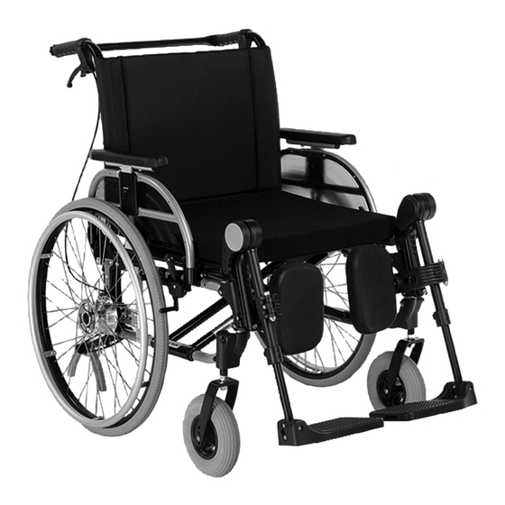
Page 7: Product Overview
4 Wheel lock (here: knee lever wheel lock) 11 Release button for quick-release axle 5 Crossbrace 12 Back support, back support upholstery 6 Frame 13 Drum brake lever (option) 7 Foot plate (segmented) 14 Push handles with stabiliser bar Start M4 XXL, Start M6 Junior... -
Page 8: Safety
7 Foot plate (segmented) 4 Safety 4.1 Explanation of warning symbols Warning regarding possible serious risks of accident or injury. WARNING Warning regarding possible risks of accident or injury. CAUTION Warning regarding possible technical damage. NOTICE Start M4 XXL, Start M6 Junior... -
Page 9: Safety Instructions For Use
Falling due to abrupt braking, rolling away of the wheelchair, damage to the wheel lock ► Do not use the wheel lock as a driving brake. ► Apply the wheel lock to prevent the wheelchair from moving on uneven ground or during transfers (e.g. into a car). Start M4 XXL, Start M6 Junior... - Page 10 Risk of collisions with other traffic participants due to lack of lighting ► Wear bright clothing or clothing with reflectors. ► Install active lighting on your product. ► Ensure that the reflectors on the product are clearly visible. Start M4 XXL, Start M6 Junior...
- Page 11 Exceeding the service life Serious injuries due to failure to observe the manufacturer’s requirements ► Using the product beyond the specified expected service life leads to increased residual risk. ► Observe the specified service life. Start M4 XXL, Start M6 Junior...
-
Page 12: Side Effects
4.5.1.1 Start M4 XXL Label Meaning A Manufacturer’s product name B CE marking C Maximum load (see section “Technical data”) D Manufacturer information/address E Serial number F Manufacturing date G Symbol for medical device Start M4 XXL, Start M6 Junior... -
Page 13: Start M6 Junior
Wheelchair ready for use • Instructions for use (user) 5.2 Options The standard model can be fitted to the user's personal requirements thanks to a large range of options. For use of these options: see Page 15 ff. Start M4 XXL, Start M6 Junior... -
Page 14: Storage
6) If necessary: Pull the part of the flap that can be fastened forwards and fasten tightly to the seat upholstery (see fig. 7). 7) Fit the seat cushion. The seat cushion is secured against sliding by being pressed on to the hook-and-loop fastener. Start M4 XXL, Start M6 Junior... -
Page 15: Use
The wheelchairs in this series fully satisfy the minimum technical requirements for wheelchairs transportable by train. However, please note that it is possible that not every individual wheelchair will fulfil the minimum require ments due to the variation in designs (please see see Page 48 for further details). Start M4 XXL, Start M6 Junior... -
Page 16: Getting In And Transferring
Each leg support can be folded up individually to make getting into the wheelchair easier. “Elevating” leg support (see fig. 10) The leg support allows positioning of the leg at different angles. Amputation leg support (see fig. 11) Alternative for installation on an “elevating” leg support. Start M4 XXL, Start M6 Junior... -
Page 17: Folding The Foot Plate Up And Down
3) Thread the other end through the eyelet on the swivel segment (see fig. 14, item 2; see fig. 15). 4) Adjust the length and fasten the hook-and-loop closure (not illustrated). Removing the calf strap 1) Undo the hook-and-loop closure. Start M4 XXL, Start M6 Junior... -
Page 18: Removing And Attaching The Leg Supports
1) Hold the leg support out to the side by 90° and insert the pivot bearing into the leg support retainer (see fig. 19, item 1). 2) Swing the leg support into the direction of travel until it engages (see fig. 18, item 2). Start M4 XXL, Start M6 Junior... -
Page 19: Adapting The Angle Of The "Elevating" Leg Support
The product is equipped with seat and back upholstery. Hook-and-loop fasteners on the seat upholstery are used to attach the seat cushion. The seat cushion ensures pressure relief during use of the wheelchair. It was chosen by qualified personnel according to the needs of the user. Start M4 XXL, Start M6 Junior... -
Page 20: Removing And Fastening The Seat Cushion
► Note that adjusting the back support angle shifts the centre of gravity. Only use the back support angle adjustment with the anti-tipper activated. ► Drive in street traffic only with a vertical back support. The product can be equipped with a fixed or optionally an angle-adjustable backrest. Start M4 XXL, Start M6 Junior... -
Page 21: Side Panels
“Plug-on” side panel (see fig. 29) These side panels can be pulled up and out of the adapter for getting into or out of the wheelchair (see item 1). The height of the forearm support can also be adjusted. Start M4 XXL, Start M6 Junior... -
Page 22: Folding Down The Side Panels
1) Push the locking button in the circular opening in to the stop (see fig. 32). 2) Slide the forearm support to the desired position. 3) Release the locking button. The forearm support locks into place automatically. Start M4 XXL, Start M6 Junior... -
Page 23: Removing The Side Panels
2) Lift up the arm support at the front end and adjust it to the desired angle (see fig. 35, item 2). 3) Let go of the release button. The arm support will be secured in its position. Adjusting the rotation setting in 15° increments 1) Pull the release button downwards (see fig. 36, item 1). Start M4 XXL, Start M6 Junior... -
Page 24: Push Handles
3) Close the clamping lever tightly. → Both push handles must be adjusted to the same height. 7.7.2 Removing the push handles Push handles of the “height-adjustable, removable” type can be removed from the back support tube when needed. Start M4 XXL, Start M6 Junior... -
Page 25: Stabiliser Bar
Tipping, falling over of the user due to wheels coming off ► After each assembly, verify the proper fit of the removable wheels. The quick-release axles must be firmly locked in the wheel attachment. Start M4 XXL, Start M6 Junior... -
Page 26: Removing And Mounting The Drive Wheels
4) Remove or mount the drive wheel. After mounting: The drive wheels must not be removable after releasing the push-button on the quick-release axle. 7.9.2 Spoke protector The spoke protector prevents the fingers from getting caught in the wheel spokes. Start M4 XXL, Start M6 Junior... -
Page 27: Caster Wheels And Caster Forks
1) Remove dirt (e.g. hairs) from the caster wheel axle between the caster wheel and caster fork (see fig. 44, item 1). 2) Lubricate the caster axle between the caster wheel and caster fork with a few drops of thin, resin-free oil (sew ing machine oil). Start M4 XXL, Start M6 Junior... -
Page 28: Wheel Locks
2) If necessary, secure the brake lever by additionally actuating the lock slide (see fig. 47, item 2). 3) Deactivate the brake by actuating the brake lever again or pressing the lock slide. The drive wheels can still be removed via the quick-release axles when the brake lever is released. Start M4 XXL, Start M6 Junior... -
Page 29: Knee Lever Wheel Lock For User And Attendant
Removing/mounting the wheel lock lever extension 1) Pull away the handle of the wheel lock lever extension forward or up (see fig. 50). 2) Fold the wheel lock lever extension either forward or to the side. Start M4 XXL, Start M6 Junior... -
Page 30: Lap Belt (Seat Belt)
If the lap belt is too loose, the user can shift/slide out to the front. • During the installation/adjustment, the lap belt is routed over parts of the seating system (e.g. over forearm supports or seat pads). This causes the lap belt to lose its retaining function. Start M4 XXL, Start M6 Junior... -
Page 31: Anti-Tipper/Swinging Anti-Tipper
Deactivation 1) Depress the spring button on the upper tube section of the anti-tipper (see fig. 52, item 1). 2) Rotate the anti-tipper upwards by 180° (see fig. 52, item 2). 3) Allow the spring button to engage. Start M4 XXL, Start M6 Junior... -
Page 32: Swinging Anti-Tipper
As the wheelchair continues to be pushed (forwards/backwards), the anti-tipper turns around its axis (see fig. 55, item 1). Once the obstacle has been overcome, the anti-tipper swings back into the start position. Start M4 XXL, Start M6 Junior... -
Page 33: Transport Wheels
The transport wheels permit movement through very narrow passages (e.g. in trains or aircraft). Transport wheels take the place of the drive wheels. In order to move, an attendant is required to push the wheel chair. Start M4 XXL, Start M6 Junior... -
Page 34: Crutch Holder With Hook-And-Loop Fastening Strap
2) Pull out the adjustment tube with the head support (see fig. 60, item 2). Attaching the head support 1) Insert the adjustment tube with the head support into the clamp fitting to the stop (see fig. 60, item 2/3). 2) Tighten the clamping lever (see fig. 60, item 1). Start M4 XXL, Start M6 Junior... -
Page 35: Tray
Prior to use in a vehicle for transporting persons with reduced mobility, the tray has to be removed. Mounting/removing the tray 1) Slide the tray onto the arm supports. 2) Pull the tray off the arm supports. Always guide the tray parallel to the arm supports to avoid tilting. Start M4 XXL, Start M6 Junior... -
Page 36: Additional Options
4) Pull up the seat upholstery until the wheelchair folds together (see fig. 62). 5) Fasten the safety strap (see fig. 63). 6) Remove the drive wheels (see Page 26). 7) Place the disassembled wheelchair in the vehicle. Start M4 XXL, Start M6 Junior... -
Page 37: Use In Vehicles For Transporting Persons With Reduced Mobility
481S00=SK030 Fixation kit • Alternative: four belt loops (e.g. from the manufacturers Q’STRAINT or Unwin Safety Systems, tested accord ing to ISO 10542-1) The qualified personnel who fitted the wheelchair can provide more information about accessories. Start M4 XXL, Start M6 Junior... -
Page 38: Using The Product In A Vehicle
2) Engage the hook of the respective vehicle side wheelchair restraint belt in the front and rear mounting eyes and tighten as firmly as possible (see fig. 65). → The product showing the correct positioning of the attachment straps (see fig. 66). Start M4 XXL, Start M6 Junior... - Page 39 The fixation points of the belt loops are marked with stickers (pattern). These stickers show where the user has to pass the belt loops around the frame tube: Start M4 XXL, Start M6 Junior...
- Page 40 5) Engage the hook of the respective vehicle side wheelchair restraint belt in the belt loop (see fig. 72, item 2). 6) Tighten the vehicle side wheelchair restraint belts at the front and rear as firmly as possible. → The product showing the correct positioning of the attachment straps (see fig. 73). Start M4 XXL, Start M6 Junior...
-
Page 41: Restrictions For Use
Option Transportation in a Remove option Secure option on vehicle for trans product porting persons with reduced mobil ity not possible Add-on drive Back support angle adjustment of 30° Back support, folding Long/passive wheelbase Start M4 XXL, Start M6 Junior... -
Page 42: Start M4 Xxl
For information on cleaning seat cushions, see the care instructions on the product or the supplied instructions for use. 7.21.1.2 Cleaning belts/straps Cleaning a belt system with metal closure INFORMATION Observe the washing recommendations on the product and the information in the corresponding instructions for use provided for the product. Start M4 XXL, Start M6 Junior... -
Page 43: Disinfection
Visual inspection of wear and tear parts (e.g., tyres, bearings) Soiling of bearings Damage to the handrim Air pressure (see information on tyre sidewall) Wear and tear of the folding mechanism Check the spoke tension on the drive wheels Start M4 XXL, Start M6 Junior... -
Page 44: Maintenance Tasks
4) Before fitting the tyre again, inspect the rim bed and tyre inner wall for foreign objects. This could have caused the puncture. 5) Before installing the tube, check that the rim band is in proper condition. The rim band protects the tube from being damaged by the ends of the spokes. Start M4 XXL, Start M6 Junior... -
Page 45: Disposal
4) Inflate the tube to the maximum pressure specified by the tyre manufacturer (see information printed on the tyre sidewall). 5) Firmly screw the valve cap onto the valve. 9 Disposal 9.1 Disposal information Return the product to the specialist dealer for disposal. Start M4 XXL, Start M6 Junior... -
Page 46: Legal Information
>30 (complies with recommendations of DIN EN 12183) Min. tyre pressure [bar] Permissible tyre type – drive wheels PU tyres, pneumatic tyres Permissible tyre type – caster wheels PU tyres, pneumatic tyres, solid rubber 1,300 Start M4 XXL, Start M6 Junior... - Page 47 [°] Angle from foot plate to seat surface [º] Fully adjustable Distance arm support to seat surface [mm] Start M4 XXL: 200 Start M4 XXL: --- Start M6 Junior: 200 Start M6 Junior: 400 Start M4 XXL, Start M6 Junior...
-
Page 48: Appendices
Maximum inclination angle on which the product will 6 (dynamic stability in all directions) remain stable [°] 9 (static stability in all directions, also when wheel lock engaged) Start M4 XXL, Start M6 Junior... - Page 49 Start M4 XXL, Start M6 Junior...
- Page 50 Start M4 XXL, Start M6 Junior...
- Page 51 · www.ottobock.de 143441 Moscow Region/Krasnogorskiy Rayon info@ottobock.com.co · www.ottobock.com.co Russian Federation Otto Bock Healthcare Products GmbH Otto Bock de Mexico S.A. de C.V. T +7 495 564 8360 · F +7 495 564 8363 Brehmstraße 16 · 1110 Wien · Austria Prolongación Calle 18 No. 178-A info@ottobock.ru · www.ottobock.ru F +43 1 5267985...
- Page 52 Ihr Fachhändler | Your specialist dealer Otto Bock Mobility Solutions GmbH Lindenstraße 13 · 07426 Königsee/Germany www.ottobock.com...
Need help?
Do you have a question about the Start M4 XXL and is the answer not in the manual?
Questions and answers