Otto Bock skippi Instructions For Use Manual
Hide thumbs
Also See for skippi:
- Instructions for use manual (106 pages) ,
- Service manual (72 pages) ,
- User instructions (55 pages)
Table of Contents
Advertisement
Quick Links
Advertisement
Table of Contents

Related Manuals for Otto Bock skippi


Summary of Contents for Otto Bock skippi
- Page 1 Skippi Instructions for use...
- Page 2 Additional options for the Skippi The power wheelchair can be equipped with the following additional options (applicable options are checked): Electronic drive-away lock* [ ] Function enabled [ ] Function disabled If enabled, the function is activated by pressing the mode button on the control panel.
-
Page 3: Table Of Contents
......19 6.1.1 Backrest .............. 40 2.7.1 General information on electromagnetic interference ............20 6.1.2 Seat angle ............40 2.7.2 Warnings regarding effects of 6.1.3 Side panel with armrest ........41 electromagnetic interference......... 21 Ottobock Skippi |... - Page 4 6.5.1 Charging .............. 60 Malfunctions/troubleshooting ......76 6.5.2 Charger ............... 62 Warning ............... 77 6.5.3 Charging process ..........63 Fault ..............77 Accessories ............63 8.2.1 Fault indication: Control panel ......79 Attendant control ..........64 4 | Ottobock Skippi...
- Page 5 10.1 Disposal information ..........89 10.2 Information on re-use ..........89 Legal information ..........90 11.1 Service life ............90 11.2 Liability ..............91 11.3 CE conformity ............91 11.4 Warranty .............. 91 11.5 Trademarks ............91 Technical data ............. 92 Ottobock Skippi |...
-
Page 6: General Information
„ It is possible to increase the display size of the PDF Intended use document. The Skippi power wheelchair for children is designed solely „ For further questions about the instructions for use, for use by children and small persons who are unable to... -
Page 7: Area Of Application
General information The Skippi is a power wheelchair for children for indoor and Area of application outdoor use according to category B of EN 12184. The The Skippi power wheelchair for children is suitable for per- power wheelchair may only be combined with the options sons having the inability to walk or walking impediments re- mentioned in these instructions for use. -
Page 8: Service
Service (see inside or back side of cover for address). NOTICE Warning regarding possible technical damage. Ottobock endeavours to support their customers in all re- spects to ensure that they are satisfied with the product long INFORMATION term. Information regarding operation. Information for service personnel. 8 | Ottobock Skippi... -
Page 9: Standards And Directives
„ The product may not be used in case of exhaustion or under the influence of alcohol or medications. „ The user must not have any mental limitations which can temporarily or permanently restrict attentiveness and judgement. Ottobock Skippi |... - Page 10 Therefore utmost caution is required near any sources of open flame or sparks, especially lit cigarettes. 10 | Ottobock Skippi...
-
Page 11: Safety Requirements For Transportation, Storage And Assembly
En- Always ensure that the seat tilt mechanism and seat height gage the brake. adjustment are lowered and the backrest is in a vertical position when using the power wheelchair in a wheelchair accessible vehicle. Ottobock Skippi |... - Page 12 (e.g. programming the control unit) required according to the individual re- quirements and abilities of the user must be completed. The adjustments may only be made by personnel who have been authorised and trained by Ottobock. 12 | Ottobock Skippi...
-
Page 13: Safety Requirements For Operation
50 mm /2". Crossing obstacles which exceed 50 mm /2" in height is not permitted. Navigating stairs is not permitted. Driving backwards should be limited to manoeuvring or short distances on level ground. Ottobock Skippi |... - Page 14 14 | Ottobock Skippi...
- Page 15 2 years regardless of the amount of wear. The footrests and armrests must not be used for getting into or out of the wheelchair since they are incapable of bearing the full weight of the body. Ottobock Skippi |...
- Page 16 The power wheelchair may only be seat height, back angle, and/or seat tilt adjustment fea- used with the seat height adjustment in its lowest posi- tures. The following particularities must be observed dur- tion until the fault is repaired. ing operation: 16 | Ottobock Skippi...
- Page 17 IP 64. Both can be used road traffic. accordingly in bad weather (e. g. rain). The control unit / push button module is approved for indoor and outdoor operation and meets the requirements regarding climate and splash water. Ottobock Skippi |...
-
Page 18: Safety Requirements For Care, Maintenance And Disposal
For this reason, (high voltage with low current; discharge via the user). the following safety precautions must be taken when However, these do not represent a health hazard. charging the batteries: 18 | Ottobock Skippi... -
Page 19: Effects Of Electromagnetic Interference On The Product And On The User
INFORMATION The functionality and operating safety of the power wheel- chair must be verified by an authorised specialist dealer at least once per year. Ottobock Skippi |... -
Page 20: General Information On Electromagnetic Interference
„ There are a number of sources of relatively intense elec- dios. tromagnetic fields in the everyday environment. Some of these sources are obvious and easy to avoid. Others are not apparent and exposure is unavoidable. However, we 20 | Ottobock Skippi... -
Page 21: Warnings Regarding Effects Of Electromagnetic Interference
(Note: wheelchair. There is no easy way to evaluate their effect on the overall immunity of the power wheelchair). Ottobock Skippi |... -
Page 22: Interference Immunity Of This Power Wheelchair
Malfunctions such as an insufficient supply of power to the brake are recognised by the software, triggering an emer- gency stop or reducing the speed of the power wheelchair. A warning signal will also sound. 22 | Ottobock Skippi... - Page 23 However, the user/attendant is able to drive the power wheelchair out of a hazardous situation at any time. The power wheelchair is fully functional again once the unit has cooled down sufficiently (this may take several minutes depending on the ambient temperature). Ottobock Skippi |...
-
Page 24: Warning Symbols And Type Plates
J Manufacturer / address The rating plate is located on the side of the K Product reference number frame below the seat. Engage the locking bar before use. Observe the information in the in- structions for use. CLOSE 24 | Ottobock Skippi... - Page 25 PSI > pound-force per square inch) A Electric driving mode: lock motor brake B Manual pushing mode: unlock motor brake Pinch points on account of the construction. Users and attendants must not reach into the danger area. Ottobock Skippi |...
-
Page 26: Product Description
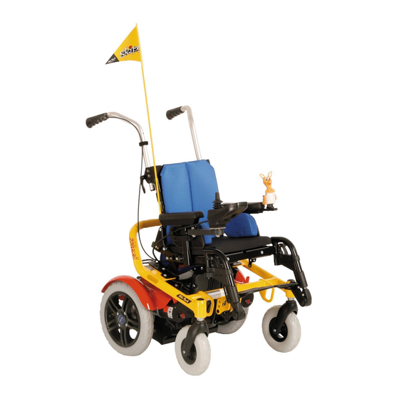
Special features of the Skippi power wheelchair include: Product description „ Compact design. The Skippi is a power wheelchair for children for indoor and „ Easy operation. outdoor use according to category B of EN 12184. The „ Easy to service due to the modular design. -
Page 27: Delivery And Preparation For Use
Locking lever a description of possible malfunctions. Footrest Detachable push handle The optional toolkit contains a set of Allen wrenches (3, 4, 5, 10 Plug with battery cable and 6 mm) and a 13 mm open-end wrench. Ottobock Skippi |... -
Page 28: Initial Operation
1) and functionality prior to initial operation. The batter- ies must be charged if necessary (see section 6.5/6.5.1). Ensure that the battery cable is seated securely in the plug (fig. 2, item 10) or push the cable into the plug if necessary. 28 | Ottobock Skippi... -
Page 29: Transportation And Storage
Transportation and storage Transportation and storage Transportation in a wheelchair accessible vehicle Once the battery packs are removed, the Skippi can be transported as a ready-to-operate power wheelchair for WARNING children. Risk of accident and injury due to improper use for transportation in a wheelchair accessible vehicle. The... - Page 30 Ensure that the wheelchair is fully secured with attachment straps for transport in a wheelchair accessible vehicle. Four eyelets are provided on the frame of the Skippi in order to attach straps (fig. 5 a, 5 b). Fig. 5 b...
-
Page 31: Required Accessories
To use the power wheelchair as a seat in a wheelchair ac- cessible vehicle, additional accessories have to be mounted (Skippi without seat height adjustment: 491S00=SK024 fix- ation kit; Skippi with seat height adjustment: 491S00=SK005 fixation kit). The qualified personnel which fit the wheelchair can provide more information. -
Page 32: Restrictions For Use
„ Stow all dismantled components securely in the wheel- chair accessible vehicle. „ Please note that certain settings on the product exclude the use of the product in a wheelchair accessible vehi- cle. Fig. 5 d Restraint lap belt hooked onto pin 32 | Ottobock Skippi... - Page 33 * The seat belt can be used to position the passenger during transportation. Using the personal restraint system is nevertheless required. For more information please refer to section 5 of the brochure on using Ottobock products in wheelchair accessible vehicles, order number 646D158. Ottobock Skippi |...
-
Page 34: Disassembling The Power Wheelchair
INFORMATION The frame and drive unit must not be separated if the Skippi is equipped with one of the following electric op- tions: Fig. 6 Removing the footrest „ Seat height adjustment „... - Page 35 5. Release the seat lock by pulling on the release strap and folding the locking bar back at the same time (fig. 10). Now the battery packs are accessible. 6. Remove the battery packs (fig. 11). Fig. 8 Removing the side panels Ottobock Skippi |...
- Page 36 8. Now the frame can be separated from the drive unit by lifting it slightly and pulling it back (fig. 13). Fig. 10 Releasing the seat lock Fig. 12 Push the step points (frame protection rollers) down Fig. 11 Removing the battery packs 36 | Ottobock Skippi...
- Page 37 Perform the steps listed above in reverse order to reassem- ble the Skippi power wheelchair. Ensure that the locking bar is pushed back into its proper position (see fig. 14 a, item 1) and both locking pins engage correctly (see fig.
-
Page 38: Storage
-15 °C and +40 °C / +5 °F and 104 °F during transportation and storage. Fig. 14a Locking bar and locking pins, engaged INFORMATION Tyres contain chemical substances that can react with other chemical substances (such as cleaning agents, acids, etc.). 38 | Ottobock Skippi... -
Page 39: Operation
Remove the fuses for shipping or when the power wheel- The following items can be adapted by the user: chair is not being used for an extended period of time. „ Back angle „ Seat angle „ Armrest height „ Armrest position Ottobock Skippi |... -
Page 40: Backrest
Risk of injury due to improper adjustment work. The available toolkit or by hand. user must not sit in the wheelchair during seat angle ad- The Skippi power wheelchair for children can be disassem- justments. bled easily by an attendant (see section 5.2). -
Page 41: Side Panel With Armrest
2. Move the side panel with armrest up or down the rail to 1. Loosen the thumb screw at the lower end of the side the desired position. panel holder. 3. Retighten the Allen head screw properly. 2. Pull the side panel with armrest up and out. Ottobock Skippi |... -
Page 42: Control Panel
3. Retighten all set screws. NOTICE Cable damage. Positioning the cable incorrectly can lead to pinching and thus damage to the cable. The cable must not be too tight or too loose. Avoid bending or crushing the cable. 42 | Ottobock Skippi... - Page 43 Fig. 20 Removing the control panel 3. Retighten all set screws. INFORMATION If the control panel rail is too long, the protruding part can simply be cut off. Ottobock Skippi |...
-
Page 44: Footrest
The standard configuration has the control panel mounted on the right side. It can also be mounted on the left side of the power wheelchair if the user so desires. Fig. 23 Footrest latch 44 | Ottobock Skippi... - Page 45 1. Loosen the corresponding two screws on the seat frame. After completing the adjustment, tighten the set screw with 2. Move the footrest holder to the desired position. a torque of 8 Nm. 3. Re-tighten the screws properly. Ottobock Skippi |...
-
Page 46: Getting In And Out
To get in from the side, the right or left side panel corre- sponding to the entry side must be removed. If possible, al- Fig. 26 Footrest holder: Adjusting the lateral position ways get in on the side opposite the control panel. 46 | Ottobock Skippi... -
Page 47: From The Front
The user can then slide into the seat from the side. This pro- cess is easier if a transfer board is used. Fig. 28 Footrests flipped up Fig. 27 Preparing to get into the chair from the side Ottobock Skippi |... -
Page 48: Control Unit
The following particularities must be observed during op- functions and components can be displayed. eration: The driving characteristics of the power wheelchair may be affected by electromagnetic fields (mobile phones or other radiating devices). Switch all mobile devices off while driving. 48 | Ottobock Skippi... - Page 49 “Electric seat function” tric options and special functions as well as warnings and errors. All display symbols are visible during the initialisation menu. phase. Ottobock Skippi |...
-
Page 50: Switching On And Off
Drive-away lock 14 Power module power wheelchair off with the on/off button while driving. In Speed level 15 Drive motor this case, the wheelchair brakes immediately until it comes Open-end wrench 16 Light to a stop. 50 | Ottobock Skippi... -
Page 51: Driving Function
The control unit of the power wheelchair switches to a safe mode at elevated temperatures and after driving uphill for extended periods of time, limiting the performance of the power wheelchair. However, the user/attendant is able to drive the power wheelchair out of a hazardous situation at Ottobock Skippi |... - Page 52 Always test the driving characteristics of the power ther the joystick is moved away from the centre position, the wheelchair after configuration / programming is complete. faster the power wheelchair will drive in this direction. Programming may only be performed by authorised, 52 | Ottobock Skippi...
-
Page 53: Battery Charge Level" Display
If all segments of the battery symbol are flashing, this means that the battery is over voltage. Since this will lead to battery damage, a warning symbol also appears. Ottobock Skippi |... -
Page 54: Range
„ Driving conditions (e.g. terrain profile, condition of sur- Battery is over voltage, with face) warning symbol „ Charging method „ Use of power options Tab. 1 Battery indicator on the control panel „ Body weight of user 54 | Ottobock Skippi... -
Page 55: Controlling Additional Electrical Functions
The electric motor moves the backrest as Electric seat tilt long as the joystick is deflected and stops at the end posi- tions. Ottobock Skippi |... -
Page 56: Drive-Away Lock
1. Press the On/Off button to turn the control unit on. order. Please ask your specialist dealer about the setting 2. Push the joystick as far forward as possible until a beep selected for your wheelchair. sounds. 56 | Ottobock Skippi... -
Page 57: Releasing And Engaging The Brake
To do so, the adjustments to the brake may only be carried out by au- brake is deactivated via the mechanical release. The brake thorised service personnel. releases are located on the right and left of the driving motors. Ottobock Skippi |... - Page 58 The control unit activates the driving function again when both brake release levers are engaged. Display symbol Information Brake is disengaged Tab. 4 Control panel display when the brake is disengaged 58 | Ottobock Skippi...
-
Page 59: Batteries
28 Ah (C5). The batteries are located in 2 battery packs The batteries must be replaced as complete units (battery below the seat of the power wheelchair (fig. 33). packs). To display the battery capacity on the control panel, see section 6.3.4. Ottobock Skippi |... -
Page 60: Charging
The battery capacity is influenced by many factors. In addition to the temperature, age of the batteries, and speed, the charging cycle also has a pronounced effect Fig. 34 Bottom of the battery pack on the capacity and therefore on the range. 60 | Ottobock Skippi... - Page 61 „ For daily use, connecting the charger overnight is recom- mended so that the full capacity is available every day. Ottobock Skippi |...
-
Page 62: Charger
The matching characteristic curve is set at the factory when the power wheelchair is shipped. The characteristic curve has to be checked if the battery charger is to be used with another power wheelchair or if new batteries are installed. 62 | Ottobock Skippi... -
Page 63: Charging Process
INFORMATION All available optional add-on components are contained on the order form and in the accessories catalogue. The Skippi power wheelchair has been designed as a mod- ular system. Certain modules can be exchanged and other Ottobock Skippi |... -
Page 64: Attendant Control
It is installed on the push handle and is height adjustable / removable. Fig. 36 Attendant control overview On / Off button Display of the selected electric seat function Battery LED Mode button Joystick Mode LED Fig. 35 Attendant control 64 | Ottobock Skippi... - Page 65 Battery charge level > 70 % Status Battery charge level Orange is lit Green is lit Speed level 1 30 % – 70 % Orange is lit Speed level 2 Red is lit Battery charge level <30 % Ottobock Skippi |...
- Page 66 Electric seat tilt drive in this direction. If the seat functions are accessed with the Mode button, then the joystick is used to select and activate the seat func- tions (see item 5 and section 6.3.6). 66 | Ottobock Skippi...
-
Page 67: Electric Seat Functions
Driving on inclines and slopes is permitted under ISO cause the spindle nut to break, causing the seat to sag or 7176-1 and 7176-2 with lowered seat height adjustment the backrest to flip back suddenly. and lowered seat tilt up to max. 6° (10 %). Ottobock Skippi |... -
Page 68: Electric Seat Height Adjustment
„ Inspect the seat height adjustment feature for visible section 2.3 “General safety instructions” and section 2.5 signs of damage at least 1 x per month and ensure all “Safety requirements for operation”. screw connections are tight. „ Check for correct tyre pressure. 68 | Ottobock Skippi... - Page 69 This is indicat- ed on the control panel. The function is activated with the joystick in Additional func- Fig. 38 Display creep speed tions / Seat functions mode (see section 6.3.5 and 7.1.1). Ottobock Skippi |...
-
Page 70: Electric Seat Tilt
(lap belt, four-point belt) and do not lean out beyond the seat surface with the seat raised. The function is activated with the joystick in Additional func- tions / Seat functions mode (see section 6.3.6 and 7.1.1). 70 | Ottobock Skippi... - Page 71 3. Remove the side panels and fold down the seat back tions / Seat functions mode (see section 6.3.6 and 7.1.1). onto the seat bottom. Fig. 41 Locking the cross bolt in the holder Fig. 40 Electric back angle adjustment Cross bolt Lock with lever Ottobock Skippi |...
-
Page 72: Mechanical Seat Options
Piston rods do not require lubrication. They are mainte- A mechanical seat tilt adjustment powered by a gas com- nance-free. pression spring is also available for the Skippi. This seat tilt adjustment is operated with a release lever at the push han- 7.3.1 Safety instructions dles. -
Page 73: Mechanically Elevating Footrest
2. Fold the control panel holder aside. 3. The pivot element locks in place again when the holder is rotated back to the original position. Fig. 42 Elevating footrest Fig. 43 Control panel holder, swing-away Ottobock Skippi |... -
Page 74: Lap Belt
„ Remove objects or clothing which get caught. The standard equipment of the power wheelchair includes a lap belt. The lap belt provides additional stabilisation and keeps the user from sliding out of the seat. Fig. 44 Applying the lap belt 74 | Ottobock Skippi... -
Page 75: Lights
Fig. 45 Rear LED light (including rear direction indicator in outer ring) current can flow (see fig. 46, right). To replace broken lamps, see the section “Replacing a de- fective bulb”. Fig. 46 Front lights Ottobock Skippi |... -
Page 76: Additional Options
The user’s envi- ronment must be taken into consideration. Electrostatic discharge may also occur if the power wheel- chair is equipped with puncture-proof tyres. Retrofitting the wheelchair with pneumatic tyres can correct this problem. 76 | Ottobock Skippi... -
Page 77: Warning
If the driving function is still not available after switching the control unit on again, the brake can be deactivated (see section 6.4) to switch over to pushing mode. Contact a specialist dealer immediately after an emergency stop! Ottobock Skippi |... - Page 78 Please con- tact your authorised specialist dealer immediately if this occurs. A fault impairs one or several functions of the power wheel- chair. The system is not fully operational until the fault has been corrected. 78 | Ottobock Skippi...
-
Page 79: Fault Indication: Control Panel
Faulty connection between the hand Check cabling / Communication error control device and controller; plug connections; (alternating flashing Defective cabling, software or signal) Contact specialist dealer hardware Battery under voltage Battery deep discharge Charge as soon as possible Ottobock Skippi |... - Page 80 Brake fault Check brake Defective brake (e.g. Bowden cable) Severe fault caused by controller, hand Emergency stop control device and / or drive motor Contact specialist dealer malfunction Tab. 9 Fault notifications on the control panel 80 | Ottobock Skippi...
-
Page 81: Fault Indication: Attendant Control
Contact specialist dealer 2 LEDs below seat Seat height adjustment are flashing motor fault Backrest / seat Electric seat function Overheating due to excessive load Cool down phase LED is flashing temperature warning Tab. 10 Attendant control fault notifications Ottobock Skippi |... -
Page 82: Defect/Failure
Maintenance intervals The proper functionality of the power wheelchair must be verified prior to every use. The activities described in tab. 11 must be performed by the user at the indicated intervals. 82 | Ottobock Skippi... - Page 83 No fault indications on the control unit Battery charger does not show any error messages via the LEDs Check plug connections Brake Activate brake lever while control unit is switched on Check that the brake function is active when the brake is engaged Ottobock Skippi |...
- Page 84 Check functionality of the belt buckle Seat attachment Check whether mounting screws are fastened properly Gas compression Visual inspection for scratches on the piston rod and oil spring (option) or leakage actuator Tab. 11 Maintenance measures and intervals 84 | Ottobock Skippi...
-
Page 85: Replace The Fuses
If the wheelchair is parked for an extended period of time or the tyres overheat (e.g. in the vicinity of radiators or in case of exposure to strong sunlight behind glass), the tyres may become permanently deformed. Ottobock Skippi |... - Page 86 6 Allen key (see fig. 49, item 1) and pull out the axle. and pull the two parts of the rim apart. 2. The defective wheel is now freely accessible and can be 4. The defective inner tube is now freely accessible and replaced. can be replaced. 86 | Ottobock Skippi...
-
Page 87: Replacing A Defective Bulb
Notch (apply screwdriver here) Damage to the lighting due to moisture penetration. LED headlight „ During installation, ensure that the plates are seated accurately in the housing. „ Ensure that the screws are seated tightly against the plate. Ottobock Skippi |... -
Page 88: Cleaning And Care
Never use a water jet or high- Fig. 51 Replacing the front direction indicator bulb pressure cleaning apparatus to clean the power wheelchair. 88 | Ottobock Skippi... -
Page 89: Disinfection
„ Prior to disinfection, clean the seat and back upholstery, as well as the seat cushion, control panel and armrest. Similar to second-hand machines or cars, products that are being re-used are subject to increased strain. Attributes and Ottobock Skippi |... -
Page 90: Legal Information
The service manual includes a service schedule for each model, detailed information, and a list of the required tools. 90 | Ottobock Skippi... -
Page 91: Liability
The product meets the requirements under the RoHS Direc- tive 2011/65/EU of the European Parliament and of the Council of 8 June 2011 on the restriction of the use of cer- tain hazardous substances in electrical and electronic equipment. Ottobock Skippi |... -
Page 92: Technical Data
235 mm Lower leg length 150 – 380 mm / 5.9" – 15" Back height 350/400/420/440/460 mm / 13.8"/15.7"/16.5"/17.3"/18.1" Back angle Manually, in 10° increments: -9°/1°/11°/21° oder 0°/10°/20°/30° Electric: adjustable by up to 25° Back angle adjustment 92 | Ottobock Skippi... - Page 93 Side panel: < 1 kg (2.2 lbs) Footrest (standard equipment): approx. 1 kg (2.2 lbs) Footrest mechanically elevating: 1.8 kg (4 lbs) Battery removable: approx. 11 kg (24 lbs) (per piece) Maximum load capacity 50 kg / 110 lbs (patient weight) Ottobock Skippi |...
- Page 94 For more information, see the included battery charger instructions for use Driving data Speed 6 km/h [3.7 mph]; 7.2 km/h [4.4 mph] (see nameplate for precise information) Maximum safe inclination Climbing ability, basic model: 7° (12 %)**** Maximum obstacle height 50 mm / 2" 94 | Ottobock Skippi...
- Page 95 “Range“ in the instructions for use (user). ****** The braking distance can be correspondingly longer due to user weight, installed options and condition of the tyres, and due to weather and sur- face conditions. Technical changes reserved. Tab. 12 Technical data Ottobock Skippi |...
- Page 97 Africa Otto Bock HealthCare Otto Bock Algérie E.U.R.L. Otto Bock France SNC Otto Bock Polska Sp. z o. o. Otto Bock de Mexico S.A. de C.V. Otto Bock Korea HealthCare Inc. Deutschland GmbH 91978 Courtaboeuf Cedex 61-029 Poznań · Poland Mackle-Ben Aknoun · Alger C.P.
- Page 98 Ihr Fachhändler/Your specialist dealer: Otto Bock Mobility Solutions GmbH Lindenstraße 13 · 07426 Königsee-Rottenbach/Germany www.ottobock.com Ottobock has a certified Quality Management System in accordance with ISO 13485.
Need help?
Do you have a question about the skippi and is the answer not in the manual?
Questions and answers