
Subscribe to Our Youtube Channel
Related Manuals for Otto Bock Skippi Plus


Summary of Contents for Otto Bock Skippi Plus
- Page 1 Skippi Plus Instructions for use ....................
- Page 2 [ ] Warning flasher [ ] Light [ ] Seat tilt [ ] Direction indicator, right [ ] Horn [ ] Back angle adjustment [ ] Direction indicator, left [ ] Other: *See the section "Use" for more information. Skippi Plus...
-
Page 3: Table Of Contents
Attendant control ..........................6.3.2 Adjustments by the user ........................6.3.2.1 Safety instructions ..........................6.3.2.2 Adjusting the control device ......................... Delivery ................................Final inspection ..........................Transport to the customer ........................Handing over the product ........................................................... Circuit breaker ........................... Skippi Plus... - Page 4 8.13 Lap belt ............................. 8.13.1 Adaptation ............................8.13.2 ..............................8.14 Control unit accessories ........................8.14.1 Separate LCD monitor ......................... 8.14.2 Attendant control ..........................8.14.3 Push-button module ..........................8.14.4 Special controls ..........................8.14.5 Adapter cable for Piko button ....................... Skippi Plus...
- Page 5 Privacy notice ............................. 11.4 Service life ............................Technical data ..............................Appendices ................................ 13.1 Threshold values for wheelchairs transportable by train ................13.2 Required tools ............................ 13.3 Torque values of the screw connections ....................13.4 Sound emission information ......................... Skippi Plus...
-
Page 6: Foreword
Modular design that allows the power wheelchair to be equipped with additional modules and installed equip ment in addition to the main components, such as various power seat functions (see Page 38), attendant con trol (see Page 50) or special controls (see Page 53), Skippi Plus... -
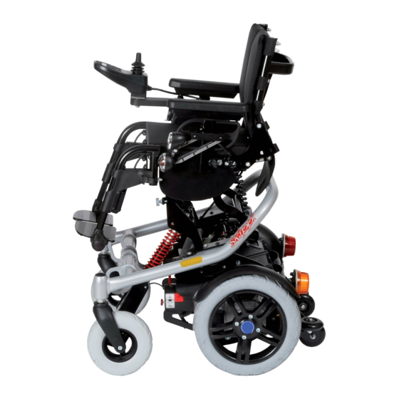
Page 7: Product Overview
2 Back support 8 Seat cushion 3 Side panel with forearm support 9 Control panel with joystick 4 Drive wheel 10 Anti-tipper / frame protection rollers 5 Battery (battery pack) 11 Plug with battery cable 6 Caster wheel Skippi Plus... -
Page 8: Intended Use
Compliance with all manufacturer specifications and all applic able legal provisions is required. Please contact the manufacturer’s service department for further information (see inside or outside of rear cover for addresses). Skippi Plus... -
Page 9: Safety
► Check your skin for intactness before and during use of the product. ► Pay attention to diligent skin care and pressure redistribution during interruptions in using the product. ► If skin damage or other problems occur during use, stop using the product. Consult the qualified personnel. Skippi Plus... -
Page 10: Side Effects
Other types of hand-held devices, such as cordless phones, laptop computers, AM/FM radios, TV sets, CD players, and cassette players, and small appliances, such as electric shavers and hair dryers, so far as we know, are not likely to cause EMI problems to your powered wheelchair. Skippi Plus... -
Page 11: Further Information
(e.g. warnings, precautions). K Symbol for separate collection of electrical and electronic devices. Components of the power wheelchair and batteries may not be disposed of in household waste. L Manufacturer’s reference number for the product variant Skippi Plus... -
Page 12: Warning Labels
The power wheelchair is normally shipped fully assembled and fitted to the personal requirements of the respective user. The scope of delivery includes: • Fitted power wheelchair with main components • Installed options • Battery charger • Instructions for use • Instructions for use for accessories (depending on equipment) Skippi Plus... -
Page 13: Accessories
The tyres should be replaced every 2 years regardless of wear and tear. • • When power wheelchairs with PU tyres are parked for longer periods, the tyres may become deformed (flat spots). This deformation will go away on its own over time while driving. Skippi Plus... -
Page 14: Preparing The Product For Use
The seat height, seat width and seat angle as well as the drive wheel suspension have been preset in accordance with the customer order. Changes to these basic settings may only be made by qualified personnel. Related information is found in the 647G695=* service manual. Skippi Plus... -
Page 15: Safety Instructions
► Turn the power wheelchair off and remove the fuse before making any adjustments. Functional tests of the electrical components are excepted from this rule. ► Before performing any work on the seat, ensure that the cushion is sufficiently protected against mechanical, chemical, and thermal effects. Skippi Plus... -
Page 16: Adjusting The Standard Seat
3) Adjust the depth of the footrest receivers to the desired position. 4) Firmly re-tighten the Allen head screws on both sides of the seat frame. 5) Put on the seat cushion, and reinstall the legrests and the side panels. Skippi Plus... -
Page 17: Adjusting The Back Support Upholstery
Deviat ing adjustments may be required in specific cases; this is the responsibility of the attending therapist. 4) Fold the fabric of the back support pad over the hook-and-loop straps and press it into place. Skippi Plus... -
Page 18: Adjusting The Belt Length
This fine-tuning should be carried out by attendants and in the presence of the user. The user should be sitting upright in the power wheelchair during fine-tuning. All parts of the product should be cleaned thoroughly before adjustments are made. Skippi Plus... -
Page 19: Safety Instructions
The user or attendant should acknowledge that they have been instructed in how to use the product and were informed of the residual risks. Depending on equipment: The supplied instructions for use for accessories have to be handed over in addi • tion. Skippi Plus... -
Page 20: Use
→ For transporting the power wheelchair, place the side panel on the seat. Installing the side panel 1) Insert the side panel into the side panel holder. 2) Re-tighten the wing screw on the side panel holder (see fig. 9). Skippi Plus... -
Page 21: Adjusting The Side Panels
► Do not reach into the danger area with your fingers when folding the legrest or footplates up or down. ► Never step on the footplates when getting in and out. ► Note projecting edges. INFORMATION For detaching/attaching the mechanically elevating leg supports: Manually elevating legrests. Skippi Plus... -
Page 22: Adjusting The Leg Supports
The backrest provides pressure redistribution and support for the upper body. 8.4.1 Folding the back support up/down The wheelchair may be delivered with the backrest folded down. It has to be folded up and secured prior to use. Skippi Plus... -
Page 23: Adjusting The Back Support Angle
► Always place the seat in a horizontal position. ► Note that the armrests are not capable of bearing full body weight, and therefore must not be used for getting into or out of the wheelchair. ► Always put on a lap belt when driving. Skippi Plus... -
Page 24: Control Unit
8.6.1 Control panel The power wheelchair is operated using the control panel. The control panel consists of a button section, LCD screen and joystick. The charging receptacle and two inputs for external buttons are located on the underside. Skippi Plus... -
Page 25: Buttons And Display Functions
[Direction indicator right] and [Direction indicator left] buttons Pressing these buttons activates/deactivates the respective front and rear direction indicators. The direction indic ator lights turn off automatically after 20 seconds. [Lights on/off] button The front and rear lights are activated/deactivated by pressing this button. Skippi Plus... - Page 26 After brief operation, the battery indicator shows the exact battery status. • A charge of 100% corresponds to 7 segments on the battery symbol. • As the remaining battery charge decreases, the LCD segments turn off one by one. Skippi Plus...
-
Page 27: Driving Functions
This includes uncontrolled movements as well as sounds that are unexpected or previously not noted or odours that deviate significantly from the state of the product at the time of delivery. ► Contact the qualified personnel. Skippi Plus... - Page 28 INFORMATION Even in the event of compliance with all applicable guidelines and standards, alarm systems (e.g. in department stores) may respond to your product. Should this happen, remove your product from the area where the alarm was triggered. Skippi Plus...
-
Page 29: Driving Notes
The hand or limb used to operate the joystick should be supported, for example on the side panel arm pad. • The joystick must not be used as the sole support for the hand or limb, because wheelchair movements and bumps could cause a loss of control. Skippi Plus... -
Page 30: Switching On And Off
Each time you switch on the control unit, it will return to the previously selected speed level. • The specialist dealer can use the parameter settings to specify the default speed level or default menu of the power wheelchair after it is turned on according to the user's requirements. Skippi Plus... -
Page 31: Selecting The Speed Levels
The maximum speed at full deflection of the joystick depends on the selected speed level. • Releasing the joystick automatically activates the brake function, bringing the power wheelchair to a halt. The mechanical brakes are activated automatically when the power wheelchair comes to a stop so that it cannot roll. Skippi Plus... -
Page 32: Range
If a special control is used, then the drive-away lock is activated via the separate LCD monitor. 1) Select Settings Menu > Additional functions Submenu (--- FEHLENDER LINK --- ff.). 2) Activate the function by moving the joystick. Skippi Plus... -
Page 33: Steering Lock
► Programming may only be performed by qualified personnel. The manufacturer of the product and the control device manufacturer are not liable in case of damage caused by programming which was not performed prop erly and/or which was not adjusted properly according to the user’s abilities. Skippi Plus... -
Page 34: Enabling/Disabling The Brakes
2) Push the brake release lever up (see fig. 21, see arrow). 3) Switch on the control unit. → The driving function is activated. Brake deactivated: warning on control panel/LCD monitor Display Information Brake released (control panel) Brake released (LCD monitor) Skippi Plus... -
Page 35: Batteries/Charging Process
In doing so, ensure that the red arrows on the bat tery packs point in the driving direction and that the plug contacts engage with the battery contacts. 2) Fold the locking bar back to prevent the battery packs from falling out (see fig. 23). Skippi Plus... -
Page 36: Battery Charging Information
► Only clean the battery charger with a dry cloth. The battery charger is designed for maintenance-free and low-maintenance batteries. Please see the instructions for use supplied with the battery charger for further details on use and on the LED dis plays. Skippi Plus... -
Page 37: Charging The Batteries
► Ensure that the cooling fins/ventilation slots on the back of the device are not covered. INFORMATION Charge the batteries of the power wheelchair for a longer time (over the course of 15 to 20 hours) once a week to ensure a long battery service life. Skippi Plus... -
Page 38: Seat
Detailed information regarding use, maintenance and repair can be found in the included instructions for use. 8.11 Power seat functions The power wheelchair can be equipped with a range of different optional power seat functions. For more information on the specific equipment of this power wheelchair, contact the qualified personnel. Skippi Plus... -
Page 39: Safety Instructions
► Observe the following guidelines: at maximum load capacity, 10 seconds of activation time must be followed by approx. 90 seconds of idle time. The power seat functions are considered independently of the driving function for this purpose. ► Only activate the power seat functions if no fault or error is present. Skippi Plus... -
Page 40: Power Seat Height Adjustment
► Use the seat tilt feature only with the backrest in the upright position. ► Drive in street traffic only with the seat tilt lowered. ► When driving with the seat tilt activated, even at home, fasten the belts and do not lean out beyond the seat surface. Skippi Plus... -
Page 41: Combined Seat Height Adjustment/Seat Tilt
► Observe the instructions for use in the sections "Controlling power seat functions" (see Page 42) and "Joy stick functions" (see Page 42). The power back angle adjustment feature enables the backrest to be tilted up to 25°. The backrest can be tilted back continuously to the angle specified above. Skippi Plus... -
Page 42: Controlling Power Seat Functions
► Drive in road traffic and on inclines and downgrades only with a vertical backrest. Always use a belt system. ► Drive with the back angle adjustment activated only for short distances at home. Always use the speed level 1 for this. Note that the field of vision is limited when driving. Always use a belt system. Skippi Plus... -
Page 43: Mechanical Seat Tilt
This cancels the blocking provided by the gas compression spring. 2) Move the legrest to the desired position. 3) Tighten the release lever (see fig. 31, item 2). → The gas compression spring is blocked again. → The legrest is adjusted. Skippi Plus... -
Page 44: Lap Belt
6) Release the respective half of the buckle. 7) Verify the adjustment. WARNING! The lap belt has to fit closely but not too tightly so the user is not injured. It should be possible to slide two fingers com fortably between the strap and thigh. Skippi Plus... -
Page 45: Use
Allow the belts to air dry. Ensure that the belts and pads are completely dry before installation. • Do not expose the belts to direct heat (e.g. sunshine, stove or radiator). • Do not iron or bleach the belts. Skippi Plus... -
Page 46: Control Unit Accessories
1 x in order to drive. Only after moving the joystick forward does the Driving menu appear (see below). • The battery symbol is shown on the control panel LCD screen: Display Information Driving information is only shown on the LCD monitor Skippi Plus... - Page 47 The Main menu is displayed after holding the [Mode] button (approx. 2 seconds) on the control panel (see • above). All important power wheelchair functions can be selected and used from here. Use the joystick to navigate from the Main menu to the Options menu (see below) and the Favourites menu • (see below): Skippi Plus...
- Page 48 Additional functions menu selectable (e.g. drive-away lock, depending on pro gramming) Horn menu selectable: Further submenus allow the horn to be turned on/off LCD environment control functions menu selectable: further submenus allow TV, phone, etc. to be controlled Skippi Plus...
- Page 49 The functions can be assigned by the authorised personnel according to the user's individual requirements. • The joystick is used to navigate in this menu, as described for the Options menu. • Press the [Mode] button on the control panel to return to the main menu. Skippi Plus...
-
Page 50: Attendant Control
[Charge level] LED display [Mode] LED indicator [Mode] button [Selected power seat function] LED indicator Joystick The attendant uses the joystick to control the speed and driving direction. When a seat option is activated, the joy stick operates this seat option. Skippi Plus... - Page 51 LCD screen (see the section "Power seat functions" > "Joystick and display functions"). The power seat functions are accessed by depressing of the "M" button for approx. 2 seconds. The currently selected seat function is indicated by the following LEDs: Skippi Plus...
-
Page 52: Push-Button Module
Depending on the power wheelchair model and programming of the push-button module, up to 5 power seat func tions (see Fig., item 1) can be controlled during normal driving operation: Display Information Power seat height adjustment Power seat tilt Skippi Plus... -
Page 53: Special Controls
647G636=*. 8.14.5 Adapter cable for Piko button INFORMATION For additional information on the user-specific adjustment of this function: see inside front cover. The power wheelchair may be equipped with an optional adapter cable and Piko buttons. Skippi Plus... -
Page 54: Additional Options
Removing/installing the control panel 1) Removing: Pull the control panel up and off the ball head. 2) Installing: Set the control panel onto the ball head and push it down. Skippi Plus... -
Page 55: Adjusting The Control Panel Position
(see fig. 43, right). INFORMATION: Carefully let the side panel with the control panel hang down. 3) Insert the side panel back into the side panel hold 4) Re-tighten the thumb screw on the side panel hold Skippi Plus... -
Page 56: Lighting For Footpaths
You can find these and other optional add-on components on the order form and in the accessories catalogue. The power wheelchair can be equipped with additional options: • Armrest accessories: Special adapters for the armrests in our accessories catalogue • Joystick top: Tetra fork, STICK S80, softball, ball top, sponge ball Skippi Plus... -
Page 57: Disassembly And Transport
► Ensure that the seat is lowered all the way and the backrest is in a vertical position prior to loading and for transporting the power wheelchair. 8.16.2 Reducing the transportation size The transportation size can be reduced in a few steps to make transporting the product easier. Skippi Plus... -
Page 58: Preparing For Transport
To reassemble the power wheelchair, the steps described above must be carried out in reverse order. If the frame was separated from the drive unit bracket for transportation of the power wheelchair, correct locking of the frame has to be ensured during assembly: Skippi Plus... -
Page 59: Use In Vehicles For Transporting Persons With Reduced Mobility
The product must be sufficiently secured during transport in vehicles for transporting persons with reduced mobil ity. The illustrations that follow show an example for anchoring in a motor vehicle. Skippi Plus... -
Page 60: Required Accessories
5 in the brochure "Transporting persons with reduced mobility", order number 646D158. 2) Turn the control unit off (see Page 30). 3) Verify brake locking. Engage the brakes if needed (see Page 34). 4) Apply the attachment straps (see below). Skippi Plus... - Page 61 Placement of the personal restraint system integrated in the vehicle for transporting persons with reduced mobility Fastening the restraint lap belt of the vehicle for transporting persons with reduced mobility is mandatory. The power wheelchair's lap belt should be used in addition to position the passenger during transportation. Skippi Plus...
-
Page 62: Restrictions For Use
*** The head support can remain on the power wheelchair if it is crash-test approved. Please refer to the order form for the approved head supports. **** The lap belt can be used to position the passenger during transportation. Using the personal restraint system is nevertheless required. Skippi Plus... -
Page 63: Care
► Maintain sufficient air pressure in the tyres. The correct tyre pressure is printed on the tyre casing and listed in the section "Technical data". The function of the product should be checked before each use. • Skippi Plus... -
Page 64: Maintenance Intervals
When brake is engaged: check braking function by try ing to push the chair Power seat adjust Visually inspect all moving components and cabling for ments damage Check that screw connections are tight Check whether mounting screws are fastened properly Skippi Plus... -
Page 65: Repair
3) Loosen and remove the 4 screws around the wheel hub. 4) Pull the drive wheel forward off the wheel hub. 5) Slide the new drive wheel onto the wheel hub. 6) Tighten all 4 screws using the torque wrench. The torque value is 25 Nm. Skippi Plus... -
Page 66: Replacing The Inner Tube And Tyre
Risk of damage to the light ► During installation, ensure that the plates are seated accurately in the housing. ► Ensure that the screws are seated tightly against the plate. INFORMATION Lamp housings and lamps can both be ordered from the specialist dealer. Skippi Plus... -
Page 67: Replacing The Battery
The control unit stores a list of all faults that occur. The specialist dealer reads this information, for example during a general overhaul of the power wheelchair. Based on the saved data, the specialist dealer determines future ser vice and maintenance intervals. Skippi Plus... -
Page 68: Types Of Notifications
Contact specialist deal controller; Defective cabling, soft ware or hardware Battery undervoltage Battery deep discharge Charge as soon as pos sible Battery cable malfunc tioning/faulty connection Check the connection to to the battery the battery (charge the Skippi Plus... -
Page 69: Attendant Control Error Overview
Mode LED Error/warning Cause Possible measure Red is flashing Various product faults More detailed information about the existing fault is shown on the LCD screen on the control panel (see Page 68 f.). Seat function LEDs Error/warning Cause Possible measure Skippi Plus... -
Page 70: Behaviour In Case Of Breakdowns
Detailed information on replacing components as well as information on the required tools can be found in the ser vice manual. 11 Legal information All legal conditions are subject to the respective national laws of the country of use and may vary accordingly. Skippi Plus... -
Page 71: Liability
Forearm support height 160–230 mm (6.3"–9") Forearm support length 235 mm (9.3") Back support height* 400/420/440/460 mm (15.7/16.5/17.3/18.1") Overall width 590 mm (23.2") Overall height 775 mm/840 mm (30.5"/33.1") Overall length With leg supports: 870 mm/940 mm (34.2"/37") Without leg supports: 640 mm/710 mm (25.2"/28") Weight when empty* 66.5 kg (146.5 lbs) Skippi Plus... - Page 72 Operating voltage 24 V DC Max. output current per motor 2 x 130 A Force for operating the joystick on the 1.6 N standard control panel Control unit accessories Model Push-button module for enAble50 control unit Protection rating IPX4 Skippi Plus...
-
Page 73: Appendices
50 mm (2") vertically Height max. 1375 mm (54.1"); including a 1.84 m (72.5") large male wheel chair user (95th percentile) Turning radius 1500 mm (59.1") Maximum weight 300 kg (661 lbs); for wheelchair with occupant, including baggage 50 mm (2") Skippi Plus... -
Page 74: Required Tools
► They fully meet the requirements according to the areas of application identified below. Area of application Maximum sound pressure level In enclosed rooms 65 db(A) Outside of enclosed rooms 75 db(A) Depending on the area of application according to ISO 7176-14 Skippi Plus... - Page 75 · www.ottobock.de 143441 Moscow Region/Krasnogorskiy Rayon info@ottobock.com.co · www.ottobock.com.co Russian Federation Otto Bock Healthcare Products GmbH Otto Bock de Mexico S.A. de C.V. T +7 495 564 8360 · F +7 495 564 8363 Brehmstraße 16 · 1110 Wien · Austria Prolongación Calle 18 No. 178-A info@ottobock.ru · www.ottobock.ru F +43 1 5267985...
- Page 76 Ihr Fachhändler | Your specialist dealer Otto Bock Mobility Solutions GmbH Lindenstraße 13 · 07426 Königsee/Germany www.ottobock.com...
Need help?
Do you have a question about the Skippi Plus and is the answer not in the manual?
Questions and answers