Siemens SINAMICS G120D Operating Instructions Manual
With control units cu250d-2
Hide thumbs
Also See for SINAMICS G120D:
- List manual (910 pages) ,
- Original instructions manual (382 pages) ,
- Operating instructions manual (374 pages)
Table of Contents
Advertisement
Quick Links
Advertisement
Table of Contents

Related Manuals for Siemens SINAMICS G120D


Summary of Contents for Siemens SINAMICS G120D
- Page 3 ___________________ Converter with control units CU250D-2 Changes in this manual Fundamental safety ___________________ instructions ___________________ SINAMICS Introduction ___________________ Description SINAMICS G120D Converter with control units ___________________ CU250D-2 Installation ___________________ Commissioning Operating Instructions ___________________ Adapt fieldbus configuration ___________________ Advanced commissioning ___________________...
-
Page 4: Legal Information
Note the following: WARNING Siemens products may only be used for the applications described in the catalog and in the relevant technical documentation. If products and components from other manufacturers are used, these must be recommended or approved by Siemens. Proper transport, storage, installation, assembly, commissioning, operation and maintenance are required to ensure that the products operate safely and without any problems. -
Page 5: Changes In This Manual
Changes in this manual Notable changes over the 04/2014 edition of the manual New functions in firmware V4.7 SP3 in Chapter Moment of inertia estimator with moment of inertia precontrol Moment of inertia estimator for automatic speed control adaptation (Page 156) Friction characteristic with automated recording of the opti- Friction characteristic (Page 153) mization of the speed controller... - Page 6 Changes in this manual Converter with control units CU250D-2 Operating Instructions, 04/2015, FW V4.7.3, A5E34261542B AB...
-
Page 7: Table Of Contents
Residual risks of power drive systems ..................19 Introduction ............................21 About the Manual ........................21 Guide through this manual ...................... 22 Description ............................23 SINAMICS G120D CU250D-2 Inverter ................... 23 Commissioning tools ....................... 25 Supported motor series......................27 Installation ............................29 Mechanical Installation......................29 4.1.1... - Page 8 Table of contents 5.2.1 Which motor fits the converter? ..................... 61 5.2.2 Introduction, V/f control, vector control .................. 62 5.2.3 Defining additional requirements for the application .............. 63 5.2.4 Encoder assignment ......................63 Basic commissioning with IOP ....................65 Basic commissioning with a PC ..................... 69 5.4.1 Creating a project ........................
- Page 9 Table of contents Overview of the converter functions ..................113 Inverter control ........................115 7.2.1 Adapt inputs and outputs ...................... 115 7.2.1.1 Digital inputs ......................... 116 7.2.1.2 Fail-safe digital input ......................117 7.2.1.3 Digital outputs ........................119 7.2.2 Switching the motor on and off ..................... 120 7.2.3 Running the motor in jog mode (JOG function) ..............
- Page 10 Table of contents 7.6.6.3 Cam sequencer ........................184 7.6.7 Referencing .......................... 185 7.6.7.1 Referencing methods ......................185 7.6.7.2 Setting the reference point approach ................... 187 7.6.7.3 Setting the flying referencing ....................193 7.6.7.4 Set reference point ....................... 198 7.6.7.5 Absolute encoder adjustment ....................200 7.6.8 Jogging ..........................
- Page 11 Technical data ............................ 345 11.1 Performance ratings Control Unit ..................345 11.2 Performance ratings Power Module ..................347 11.3 SINAMICS G120D specifications ..................348 11.4 Data regarding the power loss in partial load operation ............349 11.5 Ambient operating conditions ....................349 11.6 Current derating - depending on the installation altitude ............
- Page 12 Table of contents 11.7 Pulse frequency and current reduction ................351 11.8 Standards (PM250D) ......................352 11.9 Electromagnetic Compatibility ....................353 Appendix ............................. 357 New and extended functions ....................357 Parameter ..........................362 The device trace in STARTER ..................... 365 Interconnecting signals in the inverter .................
-
Page 13: Fundamental Safety Instructions
Fundamental safety instructions General safety instructions DANGER Danger to life due to live parts and other energy sources Death or serious injury can result when live parts are touched. • Only work on electrical devices when you are qualified for this job. •... - Page 14 Fundamental safety instructions 1.1 General safety instructions WARNING Danger to life when live parts are touched on damaged devices Improper handling of devices can cause damage. For damaged devices, hazardous voltages can be present at the enclosure or at exposed components;...
- Page 15 Fundamental safety instructions 1.1 General safety instructions WARNING Danger to life through unexpected movement of machines when using mobile wireless devices or mobile phones Using mobile wireless devices or mobile phones with a transmit power > 1 W closer than approx.
- Page 16 Fundamental safety instructions 1.1 General safety instructions NOTICE Device damage caused by incorrect voltage/insulation tests Incorrect voltage/insulation tests can damage the device. • Before carrying out a voltage/insulation check of the system/machine, disconnect the devices as all converters and motors have been subject to a high voltage test by the manufacturer, and therefore it is not necessary to perform an additional test within the system/machine.
-
Page 17: Safety Instructions For Electromagnetic Fields (Emf)
Fundamental safety instructions 1.2 Safety instructions for electromagnetic fields (EMF) Safety instructions for electromagnetic fields (EMF) WARNING Danger to life from electromagnetic fields Electromagnetic fields (EMF) are generated by the operation of electrical power equipment such as transformers, converters or motors. People with pacemakers or implants are at a special risk in the immediate vicinity of these devices/systems. -
Page 18: Industrial Security
Siemens recommends strongly that you regularly check for product updates. For the secure operation of Siemens products and solutions, it is necessary to take suitable preventive action (e.g. cell protection concept) and integrate each component into a holistic, state-of-the-art industrial security concept. -
Page 19: Residual Risks Of Power Drive Systems
Fundamental safety instructions 1.5 Residual risks of power drive systems Residual risks of power drive systems The control and drive components of a drive system are approved for industrial and commercial use in industrial line supplies. Their use in public line supplies requires a different configuration and/or additional measures. - Page 20 Fundamental safety instructions 1.5 Residual risks of power drive systems 3. Hazardous shock voltages caused by, for example, – Component failure – Influence during electrostatic charging – Induction of voltages in moving motors – Operation and/or environmental conditions outside the specification –...
-
Page 21: Introduction
Introduction About the Manual Who requires the operating instructions and what for? These operating instructions primarily address fitters, commissioning engineers and machine operators. The operating instructions describe the devices and device components and enable the target groups being addressed to install, connect-up, set, and commission the converters safely and in the correct manner. -
Page 22: Guide Through This Manual
Introduction 2.2 Guide through this manual Guide through this manual ① Inverter components and accessories. Permissible motors. Tools for commissioning. ② Install and wire the inverter and its components. Install the inverter in accordance with EMC. ③ Prepare for commissioning. Restore the inverter to factory settings. -
Page 23: Description
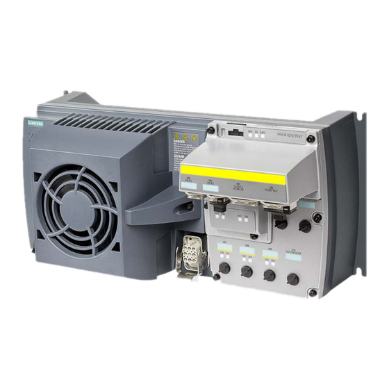
SINAMICS G120D CU250D-2 Inverter Overview The SINAMICS G120D is a converter for controlling the position of a drive. The converter consists of two parts, the Control Unit (CU) and the Power Module (PM). Table 3- 1... - Page 24 Description 3.1 SINAMICS G120D CU250D-2 Inverter Table 3- 2 PM250D Power Modules Frame Rated output Rated output Order number size power current based on High Overload (HO) 0.75 kW 2.2 A 6SL3525-0PE17-5AA1 1.5 kW 4.1 A 6SL3525-0PE21-5AA1 3.0 kW 7.7 A 6SL3525-0PE23-0AA1 4.0 kW...
-
Page 25: Commissioning Tools
Description 3.2 Commissioning tools Commissioning tools Figure 3-1 Commissioning tools - PC or IOP Handheld Kit Converter with control units CU250D-2 Operating Instructions, 04/2015, FW V4.7.3, A5E34261542B AB... - Page 26 STARTER Commissioning tool (PC soft- You obtain STARTER on a DVD (Article ware) number: 6SL3072-0AA00-0AG0) and it can be downloaded: Download STARTER (http://support.automation.siemens.com/W W/view/en/26233208) Startdrive You obtain Startdrive on a DVD (Article number: 6SL3072-4CA02-1XG0) and it can be downloaded: Startdrive (http://support.automation.siemens.com/W...
-
Page 27: Supported Motor Series
1PH8 induction motors motors Multi-motor drive is permissible, i.e. multiple mo- tors operated on one inverter. See also: Multi- motor drive (http://support.automation.siemens.com/WW/view/ en/84049346). Motors from other manufacturers Standard induction motors Converter with control units CU250D-2 Operating Instructions, 04/2015, FW V4.7.3, A5E34261542B AB... -
Page 28: 8 Operating Instructions, 04/2015, Fw V4.7.3, A5E34261542B Ab
Description 3.3 Supported motor series Converter with control units CU250D-2 Operating Instructions, 04/2015, FW V4.7.3, A5E34261542B AB... -
Page 29: Installation
Installation Mechanical Installation Fitting the Control Unit to the Power Module The inverter is delivered as two separate components - the Power Module (PM) and the Control Unit (CU). The CU must be fitted to the PM prior to any further commissioning taking place. -
Page 30: Drill Pattern Sinamics G120D
Installation 4.1 Mechanical Installation 4.1.1 Drill pattern SINAMICS G120D Drill pattern and dimensions The inverter has an identical drill pattern for all frame sizes. The drill pattern, depth and tightening torques are shown in the diagram below. Figure 4-2 SINAMICS G120D drill pattern Converter with control units CU250D-2 Operating Instructions, 04/2015, FW V4.7.3, A5E34261542B AB... - Page 31 Installation 4.1 Mechanical Installation Mounting orientation Mount the converter on a table or on a wall. The minimum clearance distances are as follows: ● Side-by-side - no clearance distance is required ● Above and below the inverter 150 mm (5.9 inches). Figure 4-3 Mounting orientation: correct (✓), impermissible (X), permissible with restrictions (!) Restrictions due to vertical mounting...
-
Page 32: Electrical Installation
Installation 4.2 Electrical Installation Electrical Installation NOTICE Material damage from inappropriate supply system V > 1% Operating the converter on an inappropriate supply system can cause damage to the converter and other loads. • Only operate the converter on supply systems with V ≤... -
Page 33: Basic Emc Rules
Installation 4.2 Electrical Installation 4.2.2 Basic EMC Rules Measures to limit Electromagnetic Interference (EMI) Listed below are the necessary measures that must be taken to ensure the correct installation of the Inverter within a system, which will minimize the effect of EMI. Cables ●... -
Page 34: Overview Of The Interfaces
Installation 4.2 Electrical Installation 4.2.3 Overview of the interfaces Interfaces of the converter ① ⑧ Digital inputs 0 … 5 with status LED HTL Encoder connection ② ⑨ Fieldbus IN and OUT (PROFINET or SSI Encoder connection PROFIBUS) ③ ⑩ 24 V DC supply IN and OUT Slot for a memory card at rear of the Control Unit... -
Page 35: Feeder Protection Of Individual Inverters
Fuses of any manufacturer with faster tripping characteristic than class RK5, e.g. JDDZ class J, time, CC, G, or CF SIEMENS circuit breaker DIVQ Intrinsically safe SIEMENS circuit breaker NKJH Converter with control units CU250D-2 Operating Instructions, 04/2015, FW V4.7.3, A5E34261542B AB... - Page 36 Installation 4.2 Electrical Installation Table 4- 3 Feeder protection with fuse, UL category JDDZ Rated power Power Module Frame Max. rated current Short-circuit current rating size of the fuse SCCR (Short circuit current rating) 0.75 kW 6SL3525-0PE17-5AA1 10 A 100 kA, 480 V 3AC 1.5 kW 6SL3525-0PE21-5AA1 15 A...
-
Page 37: Feeder Protection Of Multiple Inverters
Installation 4.2 Electrical Installation 4.2.5 Feeder protection of multiple inverters For installations with more than one inverter, the inverters are normally powered from a 400- V power bus with a T distributor. Figure 4-6 Power supply to an inverter group via a shared 400-V feeder Calculation of the feeder protection according to IEC and UL standards Calculation of the feeder protection: ●... - Page 38 Installation 4.2 Electrical Installation Example ① ② In one installation, either the inverters of group or the inverters of group are in ① operation, but never both groups and ② simultaneously. Figure 4-7 Protection of two inverter groups via a shared 400-V feeder The sum of the rated input currents is: ①...
- Page 39 Fuses of any manufacturer with faster tripping characteristic than class RK5, e.g. JDDZ class J, time, CC, G, or CF SIEMENS circuit breaker DIVQ Intrinsically safe SIEMENS circuit breaker NKJH Table 4- 7 Feeder protection with fuse, UL category JDDZ Max. rated current of the fuse...
-
Page 40: 24-V Power Supply With Multiple Inverters
Installation 4.2 Electrical Installation 4.2.6 24-V power supply with multiple inverters Installation using 24 V bus The following options are available for the 24 V supply of the inverter: 1. A T distributor with integrated power supply unit supplies the 24 V. Advantage: Low installation costs. -
Page 41: Connections And Cables
Installation 4.2 Electrical Installation 4.2.7 Connections and cables DANGER Danger of electrical shock by touching the pins in the motor terminal box The temperature sensor and motor holding brake connections are at DC link negative potential. Touching the pins in the motor terminal box can lead to death due electrical shock. - Page 42 Installation 4.2 Electrical Installation Figure 4-9 G120D CU250D-2 PROFIBUS connectors Converter with control units CU250D-2 Operating Instructions, 04/2015, FW V4.7.3, A5E34261542B AB...
- Page 43 Installation 4.2 Electrical Installation Figure 4-10 G120D CU250D-2 PROFINET connectors Converter with control units CU250D-2 Operating Instructions, 04/2015, FW V4.7.3, A5E34261542B AB...
- Page 44 Installation 4.2 Electrical Installation Figure 4-11 G120D CU250D-2 PROFINET Push-Pull connectors Converter with control units CU250D-2 Operating Instructions, 04/2015, FW V4.7.3, A5E34261542B AB...
- Page 45 Installation 4.2 Electrical Installation Figure 4-12 G120D CU250D-2 PROFINET FO terminal diagram Converter with control units CU250D-2 Operating Instructions, 04/2015, FW V4.7.3, A5E34261542B AB...
- Page 46 The detailed specifications for the cables, connectors and tools required to manufacture the necessary cables for the SINAMICS G120D are listed in the following tables. The connections that are detailed in this section relate to the physical connections that exist on the Inverter.
- Page 47 6GK1905-0EA00 3RK1902-1BA00 PROFINET Port 1 and Port 2 (M12) 6GK1901-0DB20-6AA0 3RK1902-2DA00 Encoder (M12 ) Via KnorrTec: Knorrtec (http://www.knorrtec.de/index.php/en/company- profile/siemens-solution-partner) Digital input and output (M12 ) 3RK1902-4BA00-5AA0 3RK1902-4DA00-5AA0 Table 4- 11 Push-Pull variant PROFINET and POWER connectors Connector Order number 24 V DC power supply...
- Page 48 Installation 4.2 Electrical Installation Cable lengths Cable Screening Max. length Motor Screened 15 m (49 ft) Unscreened 30 m (98 ft) Temperature sensor Screened 15 m (49 ft) Unscreened 30 m (98 ft) Motor holding brake Screened 15 m (49 ft) Unscreened 30 m (98 ft) Digital inputs...
-
Page 49: Star-Delta Motor Connection
Before you connect the motor, ensure that the motor has the appropriate connection for your application: Motor is connected in the star or delta configuration With SIEMENS motors, you will see a diagram of both connection methods on the inside of the cover of the terminal box: •... -
Page 50: Connecting The Motor Holding Brake
Installation 4.2 Electrical Installation 4.2.9 Connecting the motor holding brake WARNING Danger to life when live parts are touched in the motor terminal box The temperature sensor and motor holding brake connections are at DC link negative potential. Touching these connections can result in death or severe injury. •... -
Page 51: Factory Settings Of The Inputs And Outputs
Installation 4.2 Electrical Installation 4.2.10 Factory settings of the inputs and outputs Factory settings of the inputs and outputs of the CU250D-2 control unit In the factory settings, the fieldbus interface of the inverter is not active. Figure 4-15 Factory settings of the CU250D-2 control units Changing the function of the inputs and outputs The function of each color-identified input and output can be set. -
Page 52: Default Settings Of Inputs And Outputs
Installation 4.2 Electrical Installation 4.2.11 Default settings of inputs and outputs Default setting 26: "EPOS without fieldbus" Factory setting DO 0: p0730, DO 1: p0731 DI 0: r0722.0, …, DI 5: r0722.5 Default setting 27: "EPOS with fieldbus" DO 0: p0730, DO 1: p0731 Converter with control units CU250D-2 Operating Instructions, 04/2015, FW V4.7.3, A5E34261542B AB... -
Page 53: Connecting The Profinet Interface
The following SSI encoders have been commissioned successfully in several applications with the CU250D-2: Table 4- 15 SSI encoders Manufacturer Type / order number Details Setting Note SIEMENS 6FX2001-5xS12 Singleturn encoder p0400 = 3081 SIEMENS 1XP80X4-20 / Multiturn encoder p0400 = 3082 6FX2001-5xS24 T&R... -
Page 54: Grounding Converter And Motor
Installation 4.2 Electrical Installation 4.2.14 Grounding converter and motor Grounding the converter ● Ground the converter via the PE connection in the mains supply connector. ● Ground the connectors as shown in the diagram below. Figure 4-16 Grounding the line supply and motor connectors •... -
Page 55: Connections And Interference Suppression
Installation 4.2 Electrical Installation EMC cable glands Where cable glands are used within the installation of the system, it is recommended that EMC glands are used. The cable gland provides protection to the IP68 standard when fitted correctly. Figure 4-17 Example of a Blueglobe EMC cable gland Table 4- 16 Brass-nickel plated EMC cable gland with metric thread as per EN50262. -
Page 56: Equipotential Bonding
Installation 4.2 Electrical Installation 4.2.16 Equipotential bonding Grounding and high-frequency equipotential bonding measures Equipotential bonding within the drive system has to be established by connecting all electrical and mechanical drive components (transformer, motor and driven machine) to the grounding system. These connections are established by means of standard heavy-power PE cables, which do not need to have any special high-frequency properties. - Page 57 Figure 4-18 Grounding and high-frequency equipotential bonding measures in the drive system and in the plant For general rules for EMC compliant installation see also: EMC design guidelines (http://support.automation.siemens.com/WW/view/en/60612658/0/en) Converter with control units CU250D-2 Operating Instructions, 04/2015, FW V4.7.3, A5E34261542B AB...
-
Page 58: 8 Operating Instructions, 04/2015, Fw V4.7.3, A5E34261542B Ab
Installation 4.2 Electrical Installation Converter with control units CU250D-2 Operating Instructions, 04/2015, FW V4.7.3, A5E34261542B AB... -
Page 59: Commissioning
Commissioning Commissioning guidelines The converter must match the motor and the drive application to be able to optimally operate and protect the motor. We recommend a certain procedure when commissioning your converter. Explanation of the commissioning steps: ① Preparing for commissioning (Page 60) ②... -
Page 60: Preparing For Commissioning
Before starting commissioning, you must know the answer to the following questions: Inverter ● What are the data specifications of my inverter? → SINAMICS G120D CU250D-2 Inverter (Page 23). ● What inverter interfaces are active? → Connections and cables (Page 41). -
Page 61: Which Motor Fits The Converter
Commissioning 5.2 Preparing for commissioning 5.2.1 Which motor fits the converter? Ratio of the motor and inverter rated currents The rated current of the motor must be in the range 13% to 100% of the rated converter current. Example: With an inverter with a rated current of 10.2 A, you can operate motors whose rated currents are within the range of 1.3 A …... -
Page 62: Introduction, V/F Control, Vector Control
Commissioning 5.2 Preparing for commissioning 5.2.2 Introduction, V/f control, vector control Specifying the control mode The converter has three open-loop control and closed-loop control modes for induction motors: ● Open-loop control with U/f-characteristic (U/f control) ● Field-oriented control (sensorless vector control) ●... -
Page 63: Defining Additional Requirements For The Application
Commissioning 5.2 Preparing for commissioning 5.2.3 Defining additional requirements for the application What speed limits should be set (minimum and maximum speed)? ● Minimum speed - factory setting 0 [rpm] The minimum speed is the lowest speed of the motor independent of the speed setpoint. A minimum speed is, for example, useful for fans or pumps. - Page 64 Commissioning 5.2 Preparing for commissioning Position and speed controllers operating with HTL encoder Figure 5-3 HTL encoder on the motor axis for position and speed controllers Advantage: Favorably-priced solution. Disadvantage: Depending on the gear ratio, restrictions regarding the accuracy of the position control.
-
Page 65: Basic Commissioning With Iop
Commissioning 5.3 Basic commissioning with IOP Basic commissioning with IOP Basic commissioning wizard The Basic Commissioning wizard detailed below is for Control Units with version 4.4 software or higher. Procedure For performing the basic commissioning of the converter with the IOP operator panel, proceed the following steps: Select "Basic Commissioning..."... - Page 66 Commissioning 5.3 Basic commissioning with IOP Select the correct frequency for your Inverter and at- tached motor. The use of the 87 Hz characteristic allows the motor to operate at 1.73 times of its normal speed. At this stage the wizard will begin to ask for the data relating specifically to the attached motor.
- Page 67 Commissioning 5.3 Basic commissioning with IOP 11. Input the correct Motor Speed from the motor rating plate. This value is given in RPM. 12. Select to run or disable Motor Data Identification func- tion. This function, if active, will not start until the first run command is given to the Inverter.
- Page 68 Commissioning 5.3 Basic commissioning with IOP 17. Set the Ramp Up time in seconds. This is the time the Inverter/motor system will take from being given the run command, to reaching the selected motor speed. 18. Set the Ramp Down time in seconds. This is the time the Inverter/motor system will take from being given the OFF1 command, for the motor to reach a standstill.
-
Page 69: Basic Commissioning With A Pc
5.4 Basic commissioning with a PC Basic commissioning with a PC PC-based commissioning tools STARTER and Startdrive are PC tools to commission Siemens inverters. The graphic user interface supports you when commissioning your inverter. Most of the inverter functions are available in screen forms. -
Page 70: Creating A Project
Commissioning 5.4 Basic commissioning with a PC 5.4.1 Creating a project Creating a project Procedure In order to create a new project, proceed as follows: 1. In the menu, select "Project" → "New…". 2. Specify a name of your choice for the project. You have created a new project. - Page 71 Commissioning 5.4 Basic commissioning with a PC Figure 5-6 "Accessible nodes" in Startdrive 6. When the USB interface is appropriately set, then the "Accessible nodes" screen form shows the inverters that can be accessed. Figure 5-7 Inverters found in STARTER Figure 5-8 Inverters found in Startdrive If you have not correctly set the USB interface, then the following "No additional nodes...
- Page 72 Commissioning 5.4 Basic commissioning with a PC Setting the USB interface in STARTER Procedure Proceed as follows to set the USB interface in STARTER: 1. Set the "Access point" to "DEVICE (STARTER, Scout)" and the "PG/PC interface" to "S7USB". 2. Press the "Update" button. You have set the USB interface.
-
Page 73: Go Online And Start The Configuration Wizard
Commissioning 5.4 Basic commissioning with a PC 5.4.3 Go online and start the configuration wizard Procedure with STARTER Proceed as follows to start configuration of the inverter: 1. Select your project and go online: 2. In the following screen form, select the inverter with which you wish to go online. -
Page 74: Carry-Out Basic Commissioning
Commissioning 5.4 Basic commissioning with a PC 5.4.4 Carry-out basic commissioning Procedure Proceed as follows to carry out basic commissioning: Select the control mode. See also Section: Introduction, V/f control, vector control (Page 62) Select the I/O configuration to preassign the inverter interfaces. The possible configurations can be found in sections: Factory settings of the inputs and outputs (Page 51) and Default settings of inputs and outputs (Page 52). - Page 75 Commissioning 5.4 Basic commissioning with a PC Technological use: • [0]: In all applications that do not fall under [1] … [3] • [1]: Applications involving pumps and fans • [2]: Applications with short ramp-up and ramp-down times. However, this setting is not suitable for hoisting gear and cranes/lifting gear.
- Page 76 Commissioning 5.4 Basic commissioning with a PC The inverter can evaluate up to two encoders (see also Section: Encod- er assignment (Page 63)): 1. An HTL encoder on the motor shaft. The HTL encoder can be used for position sensing as well as for speed measurement for the speed controller.
- Page 77 Commissioning 5.4 Basic commissioning with a PC Select the encoder that you use for position sensing. You may skip this screen initially. The settings are explained in the con- text of commissioning of the basic positioner in the section: Basic posi- tioner and position control (Page 163).
-
Page 78: Adapting The Encoder Data
Commissioning 5.4 Basic commissioning with a PC 5.4.5 Adapting the encoder data Preconditions ● You have selected an encoder type that does not precisely match your encoder, because it is not included in the list of default encoder types. ● You have completely configured the drive. Procedure with STARTER Proceed as follows to adapt the encoder data: 1. -
Page 79: Identify Motor Data
Commissioning 5.4 Basic commissioning with a PC Procedure with Startdrive Proceed as follows to adapt the encoder data: 1. Select the "Motor encoder" screen form. 2. Click the "Encoder data" button. 3. You have access to the following settings in the "Encoder data" screen form: –... - Page 80 Commissioning 5.4 Basic commissioning with a PC Preconditions ● You selected a method of motor data identification during basic commissioning, e.g. measurement of the motor data while the motor is stationary. When basic commissioning is complete, the inverter issues alarm A07991. ●...
- Page 81 Commissioning 5.4 Basic commissioning with a PC Procedure with Startdrive To initiate motor data identification and optimize the motor control, proceed as follows: 1. Open the control panel. 2. Assume master control for the inverter. 3. Set the "Drive enables" 4.
-
Page 82: Restoring The Factory Setting
Commissioning 5.5 Restoring the factory setting Restoring the factory setting 5.5.1 Restoring the factory setting There are cases where something goes wrong when commissioning a drive system e.g.: ● The line voltage was interrupted during commissioning and you were not able to complete commissioning. -
Page 83: Resetting The Safety Functions To The Factory Setting
Commissioning 5.5 Restoring the factory setting 5.5.2 Resetting the safety functions to the factory setting Procedure with STARTER To reset the safety function settings to the factory setting without changing the standard settings, proceed as follows: 1. Go online. 2. Open the screen form of the safety functions. 3. -
Page 84: Restore The Settings To The Factory Settings (Without Safety Functions)
Commissioning 5.5 Restoring the factory setting Procedure with Startdrive To reset the safety function settings to the factory setting without changing the standard settings, proceed as follows: 1. Go online. 2. Select "Commissioning". 3. Select "Backing up/reset". 4. Select "Safety parameters are reset". 5. - Page 85 Commissioning 5.5 Restoring the factory setting Procedure with Startdrive Proceed as follows to reset the inverter to factory settings: 1. Go online. 2. Select "Commissioning". 3. Select "Backing up/reset". 4. Select "All parameters are reset". 5. Press the "Start" button. You have reset the inverter to factory settings.
- Page 86 Commissioning 5.5 Restoring the factory setting Converter with control units CU250D-2 Operating Instructions, 04/2015, FW V4.7.3, A5E34261542B AB...
-
Page 87: Adapt Fieldbus Configuration
Adapt fieldbus configuration Fieldbus versions of the Control Unit Fieldbus interfaces of the Control Units There are different versions of the Control Units for communication with a higher-level control system: Fieldbus Profiles S7 communi- Control Unit cation PROFIdrive PROFIsafe PROFIenergy PROFIBUS ✓... -
Page 88: Profidrive Profile For Profibus And Profinet
Adapt fieldbus configuration 6.2 PROFIdrive profile for PROFIBUS and PROFINET PROFIdrive profile for PROFIBUS and PROFINET 6.2.1 Cyclic communication 6.2.1.1 Positioner: Cyclic communication The send and receive telegrams of the inverter for cyclic communication are structured as follows: Figure 6-1 Telegrams for cyclic communication - Position control Converter with control units CU250D-2 Operating Instructions, 04/2015, FW V4.7.3, A5E34261542B AB... - Page 89 Adapt fieldbus configuration 6.2 PROFIdrive profile for PROFIBUS and PROFINET Table 6- 1 Explanation of the abbreviations Abbreviation Explanation Control word See Control and status word 1 (Page 91) See Control and status word 2 (Page 93) Status word SATZANW Selects the traversing block See Control word block selection (Page 100)
- Page 90 Adapt fieldbus configuration 6.2 PROFIdrive profile for PROFIBUS and PROFINET Interconnection of the process data Figure 6-2 Interconnection of the send words Figure 6-3 Interconnection of the receive words If you require an individual telegram for your application, you can adapt one of the pre- defined telegrams using the parameters p0922 and p2079.
-
Page 91: Control And Status Word 1
Adapt fieldbus configuration 6.2 PROFIdrive profile for PROFIBUS and PROFINET 6.2.1.2 Control and status word 1 Control word 1 (STW1) Table 6- 2 Control word 1 for active basic positioner Meaning Comments P No. 0 = OFF1 The motor brakes with the ramp-down time p1121 of the ramp- p0840[0] = function generator. - Page 92 Adapt fieldbus configuration 6.2 PROFIdrive profile for PROFIBUS and PROFINET Status word 1 (ZSW1) Table 6- 3 Status word 1 when the basic positioner is active Bit Meaning Comments P No. Telegram 110 Telegram 111 1 = Ready to start Power supply is switched on;...
-
Page 93: Control And Status Word 2
Adapt fieldbus configuration 6.2 PROFIdrive profile for PROFIBUS and PROFINET 6.2.1.3 Control and status word 2 Control word 2 (STW2) Table 6- 4 Control word 2 and interconnection in the converter Meaning Comments Interconnection Telegram 9 Telegrams 110, 111 Drive data set selection DDS, bit 0 p0820[0] = p0820[0] = r2092.0... -
Page 94: Control And Status Word For The Positioner
Adapt fieldbus configuration 6.2 PROFIdrive profile for PROFIBUS and PROFINET 6.2.1.4 Control and status word for the positioner Positioning control word (POS_STW) Table 6- 6 POS_STW and interconnection with parameters in the inverter Meaning Comments P No. 1 = Follow-up mode The inverter continuously corrects the position setpoint to p2655[0] = follow the position actual value. - Page 95 Adapt fieldbus configuration 6.2 PROFIdrive profile for PROFIBUS and PROFINET Positioning status word (POS_ZSW) Table 6- 7 POS_ZSW and interconnection with parameters in the inverter Bit Meaning Comments P No. 1 = Follow-up mode active The inverter is in the follow-up mode. p2084[0] = r2683.0 1 = Velocity limiting is active...
-
Page 96: Control And Status Word 1 For The Positioner
Adapt fieldbus configuration 6.2 PROFIdrive profile for PROFIBUS and PROFINET 6.2.1.5 Control and status word 1 for the positioner Positioning control word 1 (POS_STW1) Table 6- 8 POS_STW1 and interconnection in the converter Meaning Comments P No. Traversing block selection, bit 0 Selecting the traversing block p2625 = r2091.0 Traversing block selection, bit 1... - Page 97 Adapt fieldbus configuration 6.2 PROFIdrive profile for PROFIBUS and PROFINET Positioning status word 1 (POS_ZSW1) Table 6- 9 POS_ZSW1 and interconnection in the converter Bit Meaning Comments P No. Active traversing block bit 0 (2 Number of the currently selected traversing block. p2083[0] = r2670[0] Active traversing block bit 1 (2...
-
Page 98: Control And Status Word 2 For The Positioner
Adapt fieldbus configuration 6.2 PROFIdrive profile for PROFIBUS and PROFINET 6.2.1.6 Control and status word 2 for the positioner Positioning control word 2 (POS_STW2) Table 6- 10 POS_STW2 and interconnection with parameters in the converter Bit Meaning Comments P No. 1 = Activate follow-up mode The converter continuously corrects the position setpoint to p2655[0] =... - Page 99 Adapt fieldbus configuration 6.2 PROFIdrive profile for PROFIBUS and PROFINET Positioning status word 2 (POS_ZSW2) Table 6- 11 POS_ZSW2 and interconnection with parameters in the converter Bit Meaning Comments P No. 1 = Follow-up mode active The converter is in the follow-up mode. p2084[0] = r2683.0 1 = Velocity limiting is active...
-
Page 100: Control Word Block Selection
Adapt fieldbus configuration 6.2 PROFIdrive profile for PROFIBUS and PROFINET 6.2.1.7 Control word block selection Block selection Table 6- 12 Block selection and interconnection in the converter Meaning Comments P No. Block selection, bit 0 Example for selecting traversing p2625 = r2091.0 block number 5: Block selection, bit 1 p2626 = r2091.1... -
Page 101: Control Word Mdi Mode
Adapt fieldbus configuration 6.2 PROFIdrive profile for PROFIBUS and PROFINET 6.2.1.8 Control word MDI mode MDI mode Table 6- 14 Selection of the MDI mode and interconnection with parameters in the converter Meaning Comments P No. 0 = Relative positioning is selected The converter interprets the position setpoint as the p2648 = r2094.0 position setpoint relative to the start position. -
Page 102: Status Word Messages
Adapt fieldbus configuration 6.2 PROFIdrive profile for PROFIBUS and PROFINET 6.2.1.9 Status word messages Status word messages (MELDW) Table 6- 15 Status word for messages and interconnection with parameters in the converter Meaning Description P No. 0 = Ramp-function generator active The motor is presently accel- p2082[0] = r2199.5 erating or braking... -
Page 103: Function Block Fb283
Set the suitable telegram: Standard telegram 7, PZD-2/2 Standard telegram 9, PZD-10/5 110: SIEMENS telegram 110, PZD-12/7 111: SIEMENS telegram 111, PZD-12/12 Now you can extend the telegram by interconnecting the PZD send words and PZD receive words with signals of your choice. -
Page 104: Slave-To-Slave Communication
Adapt fieldbus configuration 6.2 PROFIdrive profile for PROFIBUS and PROFINET Change the signal interconnection of the telegram If you want to change the signal interconnection or extend telegrams, you have to do the following: Table 6- 17 Procedure Parameter Description p0922 = 999 PROFIdrive telegram selection 999:... -
Page 105: Communication Via Profinet
Adapt fieldbus configuration 6.3 Communication via PROFINET Communication via PROFINET You can either communicate via Ethernet using the inverter, or integrate the inverter in a PROFINET network. ● The inverter as an Ethernet station (Page 387) ● PROFINET IO operation (Page 106) In PROFINET IO operation, the inverter supports the following functions: –... -
Page 106: What Do You Need For Communication Via Profinet
– The configuration of the functions is described in the PROFINET system description (http://support.automation.siemens.com/WW/view/en/19292127) manual. This manual describes the control of the inverter using primary control. How to access the inverter as an Ethernet station is described in the Fieldbus function manual (Page 387) in the section "The inverter as an Ethernet station". -
Page 107: Configuring Communication To The Control
Additional information on this topic is provided in the "Fieldbuses" Function Manual, also see Manuals for your inverter (Page 387). Configuring the communication using a non-Siemens control 1. Import the device file (GSDML) of the inverter into the engineering tool for your control system. -
Page 108: Installing Gsdml
Set p0804 = 12. The inverter writes the GSDML as zipped file (*.zip) into directory /SIEMENS/SINAMICS/DATA/CFG on the memory card. 2. Unzip the GSDML file to a folder on your computer. 3. Import the GSDML into the configuring tool of your control system. -
Page 109: Activating Diagnostics Via The Control
Adapt fieldbus configuration 6.3 Communication via PROFINET Selecting a telegram Procedure Proceed as follows to set a specific telegram in the inverter: Using STARTER or an operator panel, set parameter p0922 to the appropriate value. You have set a specific telegram in the inverter. 6.3.6 Activating diagnostics via the control The converter provides the functionality to transmit fault and alarm messages (diagnostic... -
Page 110: Communication Via Profibus
Adapt fieldbus configuration 6.4 Communication via PROFIBUS Communication via PROFIBUS 6.4.1 What do you need for communication via PROFIBUS? Check the communication settings using the following table. If you answer "Yes" to the questions, you have correctly set the communication settings and can control the inverter via the fieldbus. -
Page 111: Configuring The Communication Using Simatic S7 Control
● If the inverter is not listed in the hardware library, you can either install the newest STARTER version or install the GSD of the inverter through "Extras/GSD-Install file" in HW-Config. See also GSD (http://support.automation.siemens.com/WW/view/en/22339653/133100). When you have installed the GSD, configure the communication in the SIMATIC control. 6.4.4... -
Page 112: Select Telegram
350: SIEMENS telegram 350, PZD-4/4 352: SIEMENS telegram 352, PZD-6/6 353: SIEMENS telegram 353, PZD-2/2, PKW-4/4 354: SIEMENS telegram 354, PZD-6/6, PKW-4/4 999: Extend telegrams and change signal interconnection (Page 103) The following values apply if you have enabled the "Basic positioner" function in the inverter:... -
Page 113: Advanced Commissioning
Advanced commissioning Overview of the converter functions Figure 7-1 Overview of inverter functions Converter with control units CU250D-2 Operating Instructions, 04/2015, FW V4.7.3, A5E34261542B AB... - Page 114 Advanced commissioning 7.2 Inverter control Functions, which you need to set in any application with Functions, which you only require in special applications or position control which you must adapt The functions that you must set in every application with The functions whose parameters you only need to adapt position control are shown in a dark color in the function when actually required are shown in white in the function...
-
Page 115: Inverter Control
Advanced commissioning 7.2 Inverter control Inverter control 7.2.1 Adapt inputs and outputs This chapter describes how you adapt the function of individual digital and analog inputs and outputs of the inverter. If you adapt the function of an input or output, you overwrite the settings made during the basic commissioning. -
Page 116: Digital Inputs
Advanced commissioning 7.2 Inverter control 7.2.1.1 Digital inputs Changing the function of a digital input Interconnect the status parameter of the digital input with a binector input of your choice. Binector inputs are marked with "BI" in the parameter list of the List Manual. -
Page 117: Fail-Safe Digital Input
Advanced commissioning 7.2 Inverter control 7.2.1.2 Fail-safe digital input This manual describes the STO safety function with control using a fail-safe input. Additional safety functions, additional fail-safe digital inputs, the fail-safe digital output of the converter and the control of the safety functions using PROFIsafe are described in the Safety Integrated Function Manual. - Page 118 Advanced commissioning 7.2 Inverter control Special measures when establishing connections When routing cables over longer distances, e.g. between remote control cabinets, you have the following options to reduce the risk of damaged cables of your plant or machine: ● Use shielded cables with grounded shield. ●...
-
Page 119: Digital Outputs
Advanced commissioning 7.2 Inverter control 7.2.1.3 Digital outputs Changing the function of a digital output Interconnect the digital output with a binector output of your choice. Binector outputs are marked with "BO" in the parameter list of the List Manual. Table 7- 2 Binector outputs of the inverter (selection) Deactivating digital output... -
Page 120: Switching The Motor On And Off
Advanced commissioning 7.2 Inverter control 7.2.2 Switching the motor on and off After switching the supply voltage on, the converter normally goes into the "ready to start" state. In this state, the converter waits for the command to switch-on the motor: •... - Page 121 Advanced commissioning 7.2 Inverter control The abbreviations S1 … S5b to identify the converter states are defined in the PROFIdrive profile. Converter Explanation status In this state, the converter does not respond to the ON command. The converter goes into this state under the following conditions: ON was active when switching on the converter.
-
Page 122: Running The Motor In Jog Mode (Jog Function)
Advanced commissioning 7.2 Inverter control 7.2.3 Running the motor in jog mode (JOG function) The "Jog" function is typically used to slowly move a machine part, e.g. a conveyor belt. With the "Jog" function, you switch the motor on and off using a digital input. When the motor is switched on, it accelerates to the jogging setpoint. - Page 123 Advanced commissioning 7.2 Inverter control Jog settings Parameter Description p1058 Jogging 1 speed setpoint (factory setting 150 rpm) p1059 Jogging 2 speed setpoint (factory setting -150 rpm) p1082 Maximum speed (factory setting 1500 rpm) p1110 Inhibit negative direction =0: Negative direction of rotation is enabled =1: Negative direction of rotation is inhibited p1111 Inhibit positive direction...
-
Page 124: Switching Over The Inverter Control (Command Data Set)
Advanced commissioning 7.2 Inverter control 7.2.4 Switching over the inverter control (command data set) In some applications, it must be possible to switch over the master control for operating the inverter. Example: The motor is to be operable either from a central control via the fieldbus or from a local control box via the terminal strip. - Page 125 Advanced commissioning 7.2 Inverter control In the above example, use digital input 3 to switch from one control system of the converter via digital inputs to a control system via the fieldbus. An overview of all the parameters that belong to the command data sets is provided in the List Manual.
-
Page 126: Setpoints
Advanced commissioning 7.3 Setpoints Setpoints 7.3.1 Overview You only have to set the setpoint source if you operate the converter without basic positioner, i.e. you only operate it in the speed-controlled mode. If you operate the converter in the speed-controlled mode, you must set the source for the main setpoint of the motor speed. -
Page 127: Specifying The Setpoint Via The Fieldbus
Advanced commissioning 7.3 Setpoints 7.3.2 Specifying the setpoint via the fieldbus Interconnecting the fieldbus with the main setpoint Figure 7-8 Fieldbus as setpoint source Most standard telegrams receive the speed setpoint as a second process data PZD2. Table 7- 3 Setting the fieldbus as setpoint source Parameter Remark... -
Page 128: Motorized Potentiometer As Setpoint Source
Advanced commissioning 7.3 Setpoints 7.3.3 Motorized potentiometer as setpoint source The "Motorized potentiometer" function emulates an electromechanical potentiometer. The output value of the motorized potentiometer can be set with the "higher" and "lower" control signals. Interconnecting the motorized potentiometer (MOP) with the setpoint source Figure 7-9 Motorized potentiometer as setpoint source Figure 7-10... - Page 129 Advanced commissioning 7.3 Setpoints Table 7- 5 Extended setup of motorized potentiometer Parameter Description p1030 MOP configuration (factory setting: 00110 bin) Storage active = 0: After the motor has been switched on, the setpoint = p1040 = 1: After the motor has switched off, the inverter saves the setpoint. After the motor has switched on, the setpoint = the stored value Automatic mode, ramp-function generator active (1-signal via BI: p1041) = 0: Ramp-up/ramp-down time = 0...
-
Page 130: Fixed Speed As Setpoint Source
Advanced commissioning 7.3 Setpoints 7.3.4 Fixed speed as setpoint source In many applications after switching on the motor, all that is needed is to run the motor at a constant speed or to switch between different speeds. Example: After it has been switched on, a conveyor belt only runs with two different velocities. - Page 131 Advanced commissioning 7.3 Setpoints 2. Binary selection: You set 16 different fixed setpoints. You precisely select one of these 16 fixed setpoints by a combination of four selection bits. Figure 7-13 Simplified function diagram for binary selection of the setpoints Additional information about binary selection can be found in function diagram 3010 in the List Manual.
- Page 132 Advanced commissioning 7.3 Setpoints Example: Select two fixed setpoints directly The motor should operate at different speeds as follows: ● The signal on digital input 0 switches the motor on and accelerates it to 300 rpm. ● The signal at digital input 1 accelerates the motor to 2000 rpm. ●...
-
Page 133: Setpoint Calculation
Advanced commissioning 7.4 Setpoint calculation Setpoint calculation 7.4.1 Overview of setpoint preparation You only have to set the setpoint processing if you operate the converter without basic positioner, i.e. you only operate it in the speed-controlled mode. The setpoint can be modified as follows using the setpoint processing: ●... -
Page 134: Invert Setpoint
Advanced commissioning 7.4 Setpoint calculation 7.4.2 Invert setpoint The inverter provides an option to invert the setpoint sign using a bit. As an example, the setpoint inversion is shown through a digital input. In order to invert the setpoint through the digital input DI 1, connect the parameter p1113 with a binary signal, e.g. -
Page 135: Inhibit Direction Of Rotation
Advanced commissioning 7.4 Setpoint calculation 7.4.3 Inhibit direction of rotation In the factory setting of the inverter, both motor directions of rotation are enabled. Set the corresponding parameter to a value = 1 to permanently block directions of rotation. Table 7- 10 Examples of settings to inhibit the direction of rotation Parameter Remark... -
Page 136: Skip Frequency Bands And Minimum Speed
Advanced commissioning 7.4 Setpoint calculation 7.4.4 Skip frequency bands and minimum speed Skip frequency bands The converter has four skip frequency bands that prevent continuous motor operation within a specific speed range. You can find additional information in function diagram 3050 of the List Manual, see also: Manuals for your inverter (Page 387). -
Page 137: Speed Limitation
Advanced commissioning 7.4 Setpoint calculation 7.4.5 Speed limitation The maximum speed limits the speed setpoint range for both directions of rotation. The converter generates a message (fault or alarm) when the maximum speed is exceeded. If you must limit the speed depending on the direction of rotation, then you can define speed limits for each direction. -
Page 138: Ramp-Function Generator
Advanced commissioning 7.4 Setpoint calculation 7.4.6 Ramp-function generator The ramp-function generator in the setpoint channel limits the rate of change of the speed setpoint (acceleration). Reduced acceleration lowers the accelerating torque of the motor. In this case, the motor reduces the load on the mechanical system of the driven machine. You can select between two different ramp-function generator types: ●... - Page 139 Advanced commissioning 7.4 Setpoint calculation Table 7- 13 Additional parameters to set the extended ramp-function generator Parameter Description p1115 Ramp-function generator selection (factory setting: 1) Select ramp-function generator: 0: Basic ramp-function generator 1: Extended ramp-function generator p1120 Ramp-function generator, ramp-up time (factory setting: 10 s) Accelerating time in seconds from zero speed up to the maximum speed p1082 p1121 Ramp-function generator, ramp-down time (factory setting: 10 s)
- Page 140 Advanced commissioning 7.4 Setpoint calculation Setting the extended ramp-function generator Procedure Proceed as follows to set the extended ramp-function generator: 1. Enter the highest possible speed setpoint. 2. Switch on the motor. 3. Evaluate your drive response. – If the motor accelerates too slowly, then reduce the ramp-up time. An excessively short ramp-up time means that the motor will reach its current limiting when accelerating, and will temporarily not be able to follow the speed setpoint.
- Page 141 Advanced commissioning 7.4 Setpoint calculation Basic ramp-function generator When compared to the extended ramp- function generator, the basic ramp- function generator has no rounding times. Table 7- 14 Parameters for setting the ramp-function generator Parameter Description p1115 = 0 Ramp-function generator selection (factory setting: 1) Select ramp-function generator: 0: Basic ramp-function generator 1: Extended ramp-function generator...
- Page 142 The inverter receives the value for scaling the ramp-up and ramp-down times via PZD receive word 3. You will find further information in the Internet at: FAQ (https://support.industry.siemens.com/cs/ww/en/view/82604741). Converter with control units CU250D-2 Operating Instructions, 04/2015, FW V4.7.3, A5E34261542B AB...
-
Page 143: Motor Control
Advanced commissioning 7.5 Motor control Motor control We recommend that you use vector control with encoder for a position-controlled axis. See also section: Introduction, V/f control, vector control (Page 62). 7.5.1 V/f control Overview of the U/f control The U/f control is a closed-loop speed control with the following characteristics: ●... -
Page 144: Characteristics Of U/F Control
Advanced commissioning 7.5 Motor control 7.5.1.1 Characteristics of U/f control The inverter has several U/f characteristics. Based on the characteristic, as the inverter increases in frequency the motor voltage rises. ① The voltage boost of the characteristic improves motor behavior at low speeds. The voltage boost is effective when frequencies <... -
Page 145: Selecting The U/F Characteristic
Advanced commissioning 7.5 Motor control 7.5.1.2 Selecting the U/f characteristic Table 7- 16 U/f characteristics Requirement Application examples Remark Characteristic Parameter The required Conveyor belts, roller Linear p1300 = 0 torque is inde- conveyors, chain con- The inverter equalizes the voltage drops Linear with Flux p1300 = 1 pendent of the... - Page 146 Advanced commissioning 7.5 Motor control Requirements ● Set the ramp-up time of the ramp-function generator to a value 1 s (< 1 kW) … 10 s (> 10 kW), depending on the power rating of the motor . ● Increase the starting current in steps of ≤ 5 %. Excessively high values in p1310 ... p1312 can cause the motor to overheat and switch off (trip) the inverter due to overcurrent.
-
Page 147: Vector Control With Speed Controller
Advanced commissioning 7.5 Motor control 7.5.2 Vector control with speed controller Overview Vector control consists of current control and a higher-level speed control. for induction motors Figure 7-18 Simplified function diagram for vector control with speed controller You will find complete function diagrams in the List Manual: 6020 et seq. The inverter uses the motor model to calculate the following control signals from the measured phase currents and the output voltage: ●... -
Page 148: Checking The Encoder Signal
Advanced commissioning 7.5 Motor control To achieve a satisfactory response of the controller, you must set at least the subfunctions shown with a gray background in the figure above to adapt them to your application: ● Motor and current model: In the basic commissioning, set the motor data correctly for the connection type (Y/Δ) according to the nameplate and perform stationary motor data identification. -
Page 149: Select Motor Control
Advanced commissioning 7.5 Motor control 7.5.2.2 Select motor control Vector control is already preset To achieve a good controller response, you must adapt the elements marked in gray in the figure in the overview diagram above. If you selected vector control as control mode in the basic commissioning, you will have already set the following: ●... -
Page 150: Optimizing The Speed Controller
Advanced commissioning 7.5 Motor control 7.5.2.3 Optimizing the speed controller Optimum control response - post optimization not required Preconditions for assessing the controller response: ● The moment of inertia of the load is constant and does not depend on the speed ●... - Page 151 Advanced commissioning 7.5 Motor control Procedure To optimize the speed controller, proceed as follows: 1. Switch on the motor. 2. Enter a speed setpoint of approximately 40 % of the rated speed. 3. Wait until the actual speed has stabilized. 4.
-
Page 152: Advanced Settings
Advanced commissioning 7.5 Motor control 7.5.2.4 Advanced settings - and T adaptation The K - and T adaptation suppresses possible speed controller oscillations. During basic commissioning, the inverter optimizes the speed controller using the "rotating measurement" function. If you have performed the rotating measurement, then the K - and T adaptation has been set. -
Page 153: Friction Characteristic
Advanced commissioning 7.5 Motor control 7.5.2.5 Friction characteristic Function In many applications, e.g. applications with geared motors or belt conveyors, the frictional torque of the load is not negligible. The inverter provides the possibility of precontrolling the torque setpoint, bypassing the speed controller. - Page 154 Advanced commissioning 7.5 Motor control Recording a friction characteristic After basic commissioning, the inverter sets the speeds of the intermediate points to values suitable for the rated speed of the motor. The frictional torque of all intermediate points is still equal to zero.
- Page 155 Advanced commissioning 7.5 Motor control Parameter Parameter Explanation p3820 Intermediate points of the friction characteristic [rpm; Nm] … p2839 r3840 Friction characteristic status word 1 signal: Friction characteristic OK 1 signal: Determination of the friction characteristic is active 1 signal: Determination of the friction characteristic is complete 1 signal: Determination of the friction characteristic has been aborted 1 signal: Friction characteristic positive direction r3841...
-
Page 156: Moment Of Inertia Estimator
Advanced commissioning 7.5 Motor control 7.5.2.6 Moment of inertia estimator Background From the load moment of inertia and the speed setpoint change, the inverter calculates the accelerating torque required for the motor. Via the speed controller precontrol, the accelerating torque specifies the main percentage of the torque setpoint. The speed controller corrects inaccuracies in the precontrol (feed-forward control). - Page 157 Advanced commissioning 7.5 Motor control Calculating the load torque At low speeds, the inverter calculates the load torque from the actual motor torque. The calculation takes place under the following con- ditions: • Speed ≥ p1226 • Acceleration setpoint < 8 1/s (≙...
- Page 158 Advanced commissioning 7.5 Motor control Moment of inertia precontrol In applications where the motor predominantly operates with a constant speed, the inverter can only infrequently calculate the moment of inertia using the function described above. Moment of inertia precontrol is available for situations such as these. The moment of inertia precontrol assumes that there is an approximately linear relationship between the moment of inertia and the load torque.
- Page 159 Advanced commissioning 7.5 Motor control Procedure To activate the moment of inertia estimator, proceed as follows: 1. Set p1400.18 = 1 2. Check: p1496 ≠ 0 3. Activate the acceleration model of the speed controller pre-control: p1400.20 = 1. You have activated the moment of inertia estimator. Parameter Explanation r0333...
-
Page 160: Advanced Settings
Advanced commissioning 7.5 Motor control Advanced settings Parameter Explanation p1226 Standstill detection, speed threshold (Factory setting: 20 rpm) The moment of inertia estimator only measures the load torque for speeds ≥ p1226. p1226 also defines from which speed the inverter switches-off the motor for OFF1 and OFF3. -
Page 161: Operating The Converter Without Position Controller
Advanced commissioning 7.5 Motor control 7.5.3 Operating the converter without position controller Converter factory setting In the factory setting of the converter, the basic positioner supplies the setpoint for the speed controller. Although other sources for the setpoint are available in the converter, they are however locked. - Page 162 Advanced commissioning 7.5 Motor control Table 7- 17 Parameters to changeover from position controller to speed controller Parameter Meaning p1142 Enable setpoint/inhibit setpoint (factory setting: 0) p2502 Encoder assignment (factory setting: 1) p2550 Position controller enable 2 (factory setting: 1) Converter with control units CU250D-2 Operating Instructions, 04/2015, FW V4.7.3, A5E34261542B AB...
-
Page 163: Basic Positioner And Position Control
Advanced commissioning 7.6 Basic positioner and position control Basic positioner and position control 7.6.1 Basic positioner and position control Overview Position control means controlling the position of an axis. An "axis" is a machine or system component that comprises the converter with active position control and the driven mechanical system. -
Page 164: Commissioning Sequence
7.6 Basic positioner and position control 7.6.2 Commissioning sequence We recommend that you commission the basic positioner using the "STARTER" tool. Downloading: STARTER (http://support.automation.siemens.com/WW/view/en/10804985/133200). ① Assign encoders to the axes (Page 74) ② Set the communication via the fieldbus (Page 87) ③... -
Page 165: Normalizing The Encoder Signal
Advanced commissioning 7.6 Basic positioner and position control 7.6.3 Normalizing the encoder signal 7.6.3.1 Define the resolution Distance unit (LU): the resolution of the position actual value in the inverter The inverter calculates the position actual value of the axis using the neutral position unit LU (Length Unit). - Page 166 Advanced commissioning 7.6 Basic positioner and position control 4. Check the maximum resolution based on your encoder data. 5. Calculate: Value = 360 ° / required resolution, e.g. 360 °/ 0.1 ° = 3600. Enter this value into STARTER. You have normalized the encoder signal. Parameter Meaning p2502...
-
Page 167: Modulo Range Setting
Advanced commissioning 7.6 Basic positioner and position control 7.6.3.2 Modulo range setting Description Linear axis A linear axis is an axis whose traversing range is limited in both motor directions of rotation by the mechanical system of the machine, e.g.: •... - Page 168 Advanced commissioning 7.6 Basic positioner and position control Setting the modulo range Preconditions ● You are online with the STARTER . ● You have selected the "Mechanical system" screen. Procedure To set the modulo range, proceed as follows: 1. Enable the modulo correction. 2.
-
Page 169: Checking The Actual Position Value
Advanced commissioning 7.6 Basic positioner and position control 7.6.3.3 Checking the actual position value After normalization of the encoder signal you should check the actual position value. Preconditions ● You are online with the STARTER . ● You have selected the screen for "Actual value processing". Procedure To ensure that the converter calculates the actual position value correctly, you must check the following:... -
Page 170: Setting The Backlash
Advanced commissioning 7.6 Basic positioner and position control 7.6.3.4 Setting the backlash Description Backlash (also called play, dead travel on reversing etc.) is the distance or the angle that a motor must travel through when the direction of rotation reverses until the axis actually moves in the other direction. - Page 171 Advanced commissioning 7.6 Basic positioner and position control Correcting backlash Precondition You have selected the "Mechanical system" screen. Procedure To correct the measured backlash, set the following: ● If the axis has not traveled far enough, then set a positive backlash. ●...
-
Page 172: Limiting The Positioning Range
Advanced commissioning 7.6 Basic positioner and position control 7.6.4 Limiting the positioning range Description Positioning range for linear axes The converter limits the positioning range of a linear axis using a software limit switch. The converter only accepts position setpoints that lie within the software limit switches. Figure 7-28 Limiting the positioning range of a linear axis In addition, using its digital inputs, the converter evaluates signals from stop cams. - Page 173 Advanced commissioning 7.6 Basic positioner and position control 3. Move the axis to the negative limit position in your machine. Set the position of the software limit switches to the actual position value. 4. Enable the STOP cams. 5. Interconnect the signal of the STOP cam minus with the corresponding signal of your machine.
-
Page 174: Setting The Position Controller
Advanced commissioning 7.6 Basic positioner and position control 7.6.5 Setting the position controller 7.6.5.1 Precontrol and gain Preconditions and constraints Before you optimize the position controller, the closed-loop drive speed control must be optimally set. Dynamic response and accuracy of the closed-loop position control depend heavily on the lower-level closed-loop or open-loop control or the motor speed: ●... -
Page 175: Optimizing The Position Controller
Advanced commissioning 7.6 Basic positioner and position control 7.6.5.2 Optimizing the position controller To optimize the position controller, you must move the axis with the position control and assess the control performance. How you move an axis using the STARTER is described below. - Page 176 Advanced commissioning 7.6 Basic positioner and position control 5. Adjust the integral time. Start with an integral time of 100 ms, and test your setting by traversing the axis with the active position controller using the "jog" function. Lower integral times increase the control dynamics but can, however, result in unstable controller characteristics.
- Page 177 Advanced commissioning 7.6 Basic positioner and position control 6. Following controller optimization, set the precontrol of the position controller to 100%. 7. Check the controller characteristics again. You have optimized the position controller. Parameter Meaning p2534 Speed precontrol factor p2538 Proportional gain / Kp p2539 Integral time / Tn...
-
Page 178: Limiting The Traversing Profile
Advanced commissioning 7.6 Basic positioner and position control 7.6.5.3 Limiting the traversing profile Description The converter calculates the traversing profile when positioning from specified values for velocity, acceleration and jerk (= acceleration change with respect to time). Figure 7-30 Example: Effect of jerk limiting If the axis must traverse more slowly or must accelerate at a lower rate or "softly", then you must set the relevant limits to lower values. - Page 179 Advanced commissioning 7.6 Basic positioner and position control 4. Reduce the maximum jerk, if you require softer acceleration and braking. 5. For permanent jerk limiting, set this signal to 1. You have now set the limitation of the traversing profile. Parameter Meaning p2571...
-
Page 180: Setting The Monitoring Functions
Advanced commissioning 7.6 Basic positioner and position control 7.6.6 Setting the monitoring functions 7.6.6.1 Standstill and positioning monitoring Description As soon as the setpoint for the position within a positioning operation no longer changes, then the converter sets the "Setpoint stationary" signal to 1. With this signal, the converter starts to monitor the position actual value: ●... - Page 181 Advanced commissioning 7.6 Basic positioner and position control Setting standstill monitoring and positioning monitoring Precondition You have selected the "Monitoring" screen and the "Position monitoring" tab. Procedure To set the standstill and positioning monitoring, proceed as follows: 1. Set the required positioning accuracy. 2.
-
Page 182: Following Error Monitoring
Advanced commissioning 7.6 Basic positioner and position control 7.6.6.2 Following error monitoring Description The following error is the deviation between the position setpoint and the position actual value while the converter is positioning the axis. Figure 7-32 Monitoring the following error The converter reports fault F07452 if the following error is too high. - Page 183 Advanced commissioning 7.6 Basic positioner and position control 2. If you want to evaluate the message in your higher-level control, interconnect this signal with, for example, a status bit in the fieldbus telegram. You have now set the monitoring of the following error. Parameter Meaning p2546...
-
Page 184: Cam Sequencer
Advanced commissioning 7.6 Basic positioner and position control 7.6.6.3 Cam sequencer Description The converter compares the position actual value with two different positions and therefore simulates two independent cam switching signals. If you need this function, set the cam switching position to match your particular application and appropriately interconnect the cam switching signal. -
Page 185: Referencing
Advanced commissioning 7.6 Basic positioner and position control 7.6.7 Referencing 7.6.7.1 Referencing methods Overview If you are using an incremental encoder for the position actual value, after the supply voltage is switched off, the converter loses its valid position actual value. After the supply voltage is switched on again, the converter no longer knows the reference of the axis position to the machine. - Page 186 Advanced commissioning 7.6 Basic positioner and position control Flying referencing The converter corrects its position actual value while traversing and reduces errors, e.g. caused by wheel slip or a gear ratio that has not been precisely set. Example: A pallet on a roller conveyor must be stopped at a specific position. However, the exact position of the pallet on the conveyor is only known when a sensor is passed.
-
Page 187: Setting The Reference Point Approach
Advanced commissioning 7.6 Basic positioner and position control 7.6.7.2 Setting the reference point approach Description A reference point approach generally consists of the following three steps: 1. Travel to reference cam. When it receives a signal, the axis searches in a specified direction for the reference cam. - Page 188 Advanced commissioning 7.6 Basic positioner and position control Step 2: Travel to zero mark The behavior of the axis in step 2 depends on whether a reference cam is available: When the converter reaches the reference cam, the • Reference cam available: in the opposite direction to the start axis accelerates direction...
- Page 189 Advanced commissioning 7.6 Basic positioner and position control Step 3: Travel to reference point After the converter has detected a zero mark, the axis moves with the "approach velocity reference point" to the reference point coordinate. Figure 7-37 Step 3: Travel to reference point After the load has reached the reference point coordinate, the converter sets its position setpoint and actual value to this value.
- Page 190 Advanced commissioning 7.6 Basic positioner and position control 6. Specify the reference point coordinate. 7. Specify the reference point offset. 8. Specify the max. permissible distance to the reference cam in step 1 of active referencing. 9. If a reference cam is available: Define the maximum permitted distance to the zero mark. 10.If no reference cam is available: Define the tolerance for travel to the zero mark.
- Page 191 Advanced commissioning 7.6 Basic positioner and position control Defining the digital signals for controlling referencing Procedure To define the digital signals for controlling, proceed as follows: 1. This signal starts the reference point approach. 2. This signal must be 0 for the reference point approach. 3.
- Page 192 Advanced commissioning 7.6 Basic positioner and position control Defining the analog signals for controlling referencing Procedure To define the analog signals for controlling, proceed as follows: 1. Define the signal source for the velocity override. See also section: Direct setpoint input (MDI) (Page 220). 2.
-
Page 193: Setting The Flying Referencing
Advanced commissioning 7.6 Basic positioner and position control 7.6.7.3 Setting the flying referencing Description During motion, the load passes a reference cam. The converter evaluates the reference cam signal via a suitable fast digital input, and corrects its calculated position during travel. The fast digital inputs of the converter used for flying referencing are also called probe inputs. - Page 194 Advanced commissioning 7.6 Basic positioner and position control Procedure To set the flying referencing, proceed as follows: 1. Set with which edge of the reference cam signal the converter references its position actual value: 0: Rising edge 1: Falling edge 2.
- Page 195 Advanced commissioning 7.6 Basic positioner and position control 1000 LU. The converter corrects the reference point during travel by 2 LU, however, moves to the old target position 1500 LU. 8. Set the reference point coordinate p2599 via the expert list in the STARTER. 9.
- Page 196 Advanced commissioning 7.6 Basic positioner and position control Defining the digital signals for controlling referencing Procedure To define the digital signals for controlling, proceed as follows: 1. This signal starts flying referencing. 2. For flying referencing, this signal must be 1. The other signals are of no significance for flying referencing.
- Page 197 Advanced commissioning 7.6 Basic positioner and position control Parameter Meaning p2595 Start referencing p2598 Reference point coordinate, signal source p2599 Reference point coordinate value p2601 Flying referencing, inner window p2602 Flying referencing, outer window p2603 Flying referencing, relative positioning mode p2612 Reference point approach, reference cam r2684.11...
-
Page 198: Set Reference Point
Advanced commissioning 7.6 Basic positioner and position control 7.6.7.4 Set reference point Description Position the load, e.g. using the "jog" function, at the reference position in the machine. Figure 7-40 Set reference point Activate 'set home position' Precondition You have selected the "Homing" screen. Procedure To activate 'set home position', proceed as follows: 1. - Page 199 Advanced commissioning 7.6 Basic positioner and position control 2. In STARTER, proceed in the expert list and set p2599 to the reference point coordinate. You have now activated 'set home position'. Parameter Meaning p2596 Set reference point p2598 Reference point coordinate, signal source p2599 Reference point coordinate value r2684.11...
-
Page 200: Absolute Encoder Adjustment
Advanced commissioning 7.6 Basic positioner and position control 7.6.7.5 Absolute encoder adjustment Absolute encoder adjustment Precondition 1. You have positioned the axis (e.g. using the "jog" function) to the reference position in the machine. 2. You have selected the "Homing" screen. 3. - Page 201 Advanced commissioning 7.6 Basic positioner and position control Parameter Meaning p2598 Reference point coordinate, signal source p2599 Reference point coordinate value p2507 Absolute encoder adjustment status Error has occurred in the adjustment Absolute encoder was not adjusted Absolute encoder was not adjusted and encoder adjustment was initiated Absolute encoder adjusted Converter with control units CU250D-2 Operating Instructions, 04/2015, FW V4.7.3, A5E34261542B AB...
-
Page 202: Jogging
Advanced commissioning 7.6 Basic positioner and position control 7.6.8 Jogging 7.6.8.1 Jog velocity Description Only input a setpoint velocity for the converter for velocity jog. With the signal "Jogging 1" or "Jogging 2", the converter accelerates the axis to the relevant setpoint velocity. The converter stops the axis when the respective "Jog"... -
Page 203: Incremental Jogging
Advanced commissioning 7.6 Basic positioner and position control 7.6.8.2 Incremental jogging Description In the case of incremental jogging, input a relative traversing distance and a velocity setpoint into the converter. With the signals "Jogging 1" or "Jogging 2" the converter positions the axis by the respective travel path. - Page 204 Advanced commissioning 7.6 Basic positioner and position control 7. If you use the incremental jog, set the relative position setpoint for the "jogging 1" function. This value has no significance for velocity jogging. 8. If you use the incremental jog, set the relative position setpoint for the "jogging 2" function.
-
Page 205: Traversing Blocks
Advanced commissioning 7.6 Basic positioner and position control 7.6.9 Traversing blocks Description A traversing block describes a positioning instruction for the drive. The converter saves 16 different traversing blocks, which it normally executes one after the other. However, you can also directly select a specific traversing block or skip traversing blocks. - Page 206 Advanced commissioning 7.6 Basic positioner and position control Job and parameters Table 7- 19 Job and parameters Parameter Meaning Positioning Axis absolute or relative positioning. • Rotary axis with modulo correction in a positive or • negative direction, absolute positioning. Travel to fixed Force [N] or torque Traverse axis to a fixed stop:...
- Page 207 Advanced commissioning 7.6 Basic positioner and position control Conditions for advance Table 7- 20 Advance: Jump condition to the next traversing block Condition Meaning Traversing block CONTINUE If the axis has reached the setpoint position and has come WITH STOP to a standstill, the converter executes the next traversing block.
- Page 208 Advanced commissioning 7.6 Basic positioner and position control Programming traversing blocks Precondition 1. You have selected the "Traversing blocks" screen. 2. You select the "Program traversing blocks" button. Procedure To program the traversing blocks, proceed as follows: 1. Assign a unique number for each traversing block. 2.
- Page 209 Advanced commissioning 7.6 Basic positioner and position control Define digital signals for controlling Procedure To define the digital signals for controlling the traversing blocks, proceed as follows: 1. Define the signal for the start of the traversing block. The signal change 0 → 1 starts the currently selected traversing block. 2.
- Page 210 Advanced commissioning 7.6 Basic positioner and position control Define analog signals for controlling Procedure To define the analog signals for controlling the traversing blocks, proceed as follows: 1. Change the signal source for the velocity override, if required. The velocity override refers to the velocity values you have set in the screen for programming the traversing blocks.
- Page 211 Advanced commissioning 7.6 Basic positioner and position control 5. Specify the edge with which the inverter jumps to the next traversing block: 0: Rising edge 1: Falling edge You have now defined an external signal for the block change. Parameter Meaning p0488 Probe 1, input terminal...
- Page 212 Advanced commissioning 7.6 Basic positioner and position control Parameter Meaning p2623[0…n] Traversing block, job mode Value = 0000 cccc bbbb aaaa cccc = 0000 Positioning Absolute mode cccc = 0001 Relative cccc = 0010 Absolute positive (only for rotary axis with modulo cor- rection) cccc = 0011 Absolute negative (only for rotary axis with modulo...
-
Page 213: Travel To Fixed Stop
Advanced commissioning 7.6 Basic positioner and position control 7.6.9.1 Travel to fixed stop Preconditions The "Travel to fixed stop" function is only possible with the control type vector control with encoder (VC): "Travel to fixed stop" is not possible with the following types of control: ●... - Page 214 Advanced commissioning 7.6 Basic positioner and position control Fixed stop has been reached You have two options to define when the fixed stop is reached: 1. Fixed stop via an external sensor: At the fixed stop, the load actuates an external sensor. The sensor signals the converter that the fixed stop has been reached.
- Page 215 Advanced commissioning 7.6 Basic positioner and position control Set travel to fixed stop Precondition 1. You have programmed "Travel to fixed stop" as traversing block. See also section: Traversing blocks (Page 205). 2. If you select the "Programming traversing blocks" button, the "Configuration of fixed stop" button appears.
- Page 216 Advanced commissioning 7.6 Basic positioner and position control Procedure: Fixed stop using an external signal To set "Travel to fixed stop" using an external signal, proceed as follows: 1. Select "Fixed stop using an external signal". 2. Interconnect the sensor that signals when the fixed stop is reached with this signal. 3.
- Page 217 Advanced commissioning 7.6 Basic positioner and position control Procedure: Fixed stop using maximum following error To set "Travel to fixed stop" using maximum following error, proceed as follows: 1. Select "Fixed stop using maximum following error": 2. Set the following error that the inverter uses to detect the fixed stop. 3.
-
Page 218: Examples
Advanced commissioning 7.6 Basic positioner and position control 7.6.9.2 Examples 1. Example Table 7- 22 Traversing blocks Ind. Par. Mode Advance POSITIONING RELATIVE 10000 5000 CONTINUE WITH STOP POSITIONING ABSOLUTE 5000 Figure 7-44 Positioning an axis using traversing blocks Converter with control units CU250D-2 Operating Instructions, 04/2015, FW V4.7.3, A5E34261542B AB... - Page 219 Advanced commissioning 7.6 Basic positioner and position control 2. Example Table 7- 23 Traversing blocks Ind. Par. Mode Advance POSITIONING RELATIVE 10000 2000 CONTINUE EXTERNAL ALARM POSITIONING RELATIVE 10000 5000 CONTINUE EXTERNAL ALARM POSITIONING ABSOLUTE 5000 The converter only goes to the next traversing block for the 0 → 1 change of the "External block selection"...
-
Page 220: Direct Setpoint Input (Mdi)
Advanced commissioning 7.6 Basic positioner and position control 7.6.10 Direct setpoint input (MDI) Description For direct setpoint input (MDI, Manual Data Input), a higher-level control provides the converter with the position setpoint and traversing profile. Example 1 The higher-level control specifies the value of the setpoint either as a relative or an absolute position setpoint: Figure 7-46 Axis with direct setpoint input (MDI) positioning... - Page 221 Advanced commissioning 7.6 Basic positioner and position control Defining the digital signals for controlling direct setpoint input Precondition You have selected the "Direct setpoint input (MDI)" screen. Procedure Interconnect the signals to control the direct setpoint input using the appropriate signals from your machine control.
- Page 222 Advanced commissioning 7.6 Basic positioner and position control ⑤ Positioning mode: These signals are only effective ⑨ if, in the interface for analog sig- 0: Relative (see also bit ⑥ nals, the value is not inter- 1: Absolute (the axis must be referenced). connected.
- Page 223 Advanced commissioning 7.6 Basic positioner and position control Defining the analog signals for controlling direct setpoint input Precondition You have selected the "Direct setpoint input (MDI)" screen. Procedure Interconnect the signals to control the direct setpoint input using the appropriate signals from your machine control: ①...
- Page 224 Advanced commissioning 7.6 Basic positioner and position control Set fixed setpoint In some applications it is sufficient if the inverter moves the axis for each task in the same way, absolute or relative to the position setpoint. This approach can be achieved with fixed setpoints.
- Page 225 Advanced commissioning 7.6 Basic positioner and position control Parameter Meaning p2640 Intermediate stop (0 signal) p2641 Reject traversing job (0 signal) p2642 Direct setpoint input/MDI, position setpoint p2643 Direct setpoint input/MDI, velocity setpoint p2644 Direct setpoint input/MDI, acceleration override p2645 Direct setpoint input/MDI, deceleration override p2646 Velocity override...
-
Page 226: Protection Functions
Advanced commissioning 7.7 Protection functions Protection functions The frequency inverter offers protective functions against overtemperature and overcurrent for both the frequency inverter as well as the motor. Further, the frequency inverter protects itself against an excessively high DC link voltage when the motor is regenerating. 7.7.1 Inverter temperature monitoring The inverter temperature is essentially defined by the following effects:... - Page 227 Advanced commissioning 7.7 Protection functions Overload response for p0290 = 0 The inverter responds depending on the control mode that has been set: ● In vector control, the inverter reduces the output current. ● In U/f control, the inverter reduces the speed. Once the overload condition has been removed, the inverter re-enables the output current or speed.
- Page 228 Advanced commissioning 7.7 Protection functions Overload response for p0290 = 3 If you operate the inverter with increased pulse frequency, then the inverter reduces its pulse frequency starting at the pulse frequency setpoint p1800. In spite of the temporarily reduced pulse frequency, the maximum output current remains unchanged at the value that is assigned to the pulse frequency setpoint.
-
Page 229: Motor Temperature Monitoring Using A Temperature Sensor
Advanced commissioning 7.7 Protection functions 7.7.2 Motor temperature monitoring using a temperature sensor You can use one of the following sensors to protect the motor against overtemperature: ● Temperature switch (e. g. bi-metal switch) ● PTC sensor ● KTY 84 sensor Connect the motor's temperature sensor through the motor output cable on the Power Module. - Page 230 Advanced commissioning 7.7 Protection functions PTC sensor The converter interprets a resistance > 1650 Ω as being an overtemperature and responds according to the setting for p0610. The converter interprets a resistance < 20 Ω as being a short-circuit and responds with alarm A07015.
- Page 231 Advanced commissioning 7.7 Protection functions Setting parameters for the temperature monitoring Parameter Description p0335 Specify the motor cooling 0: Natural cooling - with fan on the motor shaft (factory setting) 1: Forced ventilation - with a separately driven fan 2: Liquid cooling 128: No fan p0601 Motor-temperature sensor type...
-
Page 232: Protecting The Motor By Calculating The Motor Temperature
Advanced commissioning 7.7 Protection functions 7.7.3 Protecting the motor by calculating the motor temperature The converter calculates the motor temperature based on a thermal motor model. Requirements The inverter can only calculate a realistic motor temperature if the following requirements are met: ●... - Page 233 Advanced commissioning 7.7 Protection functions Parameter Description p0612 Mot_temp_mod activation 1 signal: Activate motor temperature model 1 (I2t) for permanently excited synchronous motors 1 signal: Activate motor temperature model 2 for asynchronous motors 1 signal: Activate motor temperature model 3 for 1FK7 encoderless synchro- nous motors p0612.02 cannot be set for every inverter.
-
Page 234: Overcurrent Protection
Advanced commissioning 7.7 Protection functions 7.7.4 Overcurrent protection The vector control ensures that the motor current remains within the set torque limits. If you use U/f control, you cannot set any torque limits. The U/f control prevents too high a motor current by influencing the output frequency and the motor voltage (I-max controller). -
Page 235: Application-Specific Functions
Advanced commissioning 7.8 Application-specific functions Application-specific functions 7.8.1 Functions that match the application The inverter offers a series of functions that you can use depending on your particular application: ● Unit changeover (Page 236) ● Braking functions – Electrically braking the motor (Page 240) –... -
Page 236: Unit Changeover
Advanced commissioning 7.8 Application-specific functions 7.8.2 Unit changeover Description With the unit changeover function, you can adapt the inverter to the line supply (50/60 Hz) and also select US units or SI units as base units. Independent of this, you can define the units for process variables or change over to percentage values. -
Page 237: Changing Over The Motor Standard
Advanced commissioning 7.8 Application-specific functions 7.8.2.1 Changing over the motor standard You change over the motor standard using p0100. The following applies: ● p0100 = 0: IEC motor (50 Hz, SI units) ● p0100 = 1: NEMA motor (60 Hz, US units) ●... -
Page 238: Changing Over The Unit System
Advanced commissioning 7.8 Application-specific functions 7.8.2.2 Changing over the unit system You change over the unit system using p0505. The following selection options are available: ● p0505 = 1: SI units (factory setting) ● p0505 = 2: SI units or % relative to SI units ●... - Page 239 Advanced commissioning 7.8 Application-specific functions 4. Select process variables of the technology controller 5. Adapting to the line supply 6. Save your settings. 7. Go online. The inverter signals that offline, other units and process variables are set than in the inverter itself. 8.
-
Page 240: Electrically Braking The Motor
Advanced commissioning 7.8 Application-specific functions 7.8.3 Electrically braking the motor Braking with the motor in generating mode If the motor brakes the connected load electrically, it will convert the kinetic energy of the motor to electrical energy. The electrical energy E released on braking the load is proportional to the moment of inertia J of the motor and load and to the square of the speed n. - Page 241 Advanced commissioning 7.8 Application-specific functions The DC-braking function is possible only for induction motors. DC braking when falling below a start speed DC braking when a fault occurs Precondition: p1230 = 1 and p1231 = 14 Precondition: Fault number and fault response are assigned using p2100 and p2101 DC braking initiated using a control command DC braking when switching off the motor...
- Page 242 Advanced commissioning 7.8 Application-specific functions DC braking when the motor is switched off 1. The higher-level control switches off the motor (OFF1 or OFF3). 2. The motor brakes along the down ramp to the speed for the start of DC braking. 3.
-
Page 243: Braking With Regenerative Feedback To The Line
Advanced commissioning 7.8 Application-specific functions 7.8.3.2 Braking with regenerative feedback to the line The typical applications for braking with energy recovery (regenerative feedback into the line supply) are as follows: ● Hoist drives ● Centrifuges ● Unwinders For these applications, the motor must brake for longer periods of time. The inverter can feed back up to 100% of its rated power into the line supply (referred to "High Overload"... -
Page 244: Motor Holding Brake
Advanced commissioning 7.8 Application-specific functions 7.8.4 Motor holding brake The motor holding brake holds the motor in position when it is switched off. If the setting is correct, the motor will produce an electrical holding torque before the inverter opens the brake. - Page 245 Advanced commissioning 7.8 Application-specific functions 3. When the first of the two times (p1227 or p1228) has elapsed, the inverter issues the command to close the brake. 4. After the "motor holding brake closing time" p1217, the inverter switches off the motor. The motor holding brake must close within the time p1217.
- Page 246 Advanced commissioning 7.8 Application-specific functions Procedure To commission the "motor holding brake" function, proceed as follows: 1. Set p1215 = 1. The "Motor holding brake" function" is enabled. 2. Check the magnetizing time p0346; the magnetizing time is pre-assigned during commissioning and must be greater than zero.
- Page 247 Advanced commissioning 7.8 Application-specific functions Table 7- 28 Setting the control logic of the motor holding brake Parameter Description p1215 = 1 Enable motor holding brake 0 Motor holding brake locked (factory setting) 1 Motor holding brake just like the sequence control 2: Motor holding brake permanently open 3: Motor holding brake just like the sequential control, connected via BICO p1216...
-
Page 248: System Protection
Advanced commissioning 7.8 Application-specific functions 7.8.5 System protection In many applications, monitoring the motor speed and torque provides information about the plant or system status. By setting the appropriate responses in the case of faults, failures and damage to the plant or system can be avoided. Examples: ●... -
Page 249: No-Load Monitoring, Blocking Protection, Stall Protection
Advanced commissioning 7.8 Application-specific functions 7.8.5.1 No-load monitoring, blocking protection, stall protection No-load monitoring Principle of operation If the motor current is below the value of p2179 for the time set in p2180, using bit 11 of status word 1 for monitoring functions (r2197.11), the converter outputs the "Output load not available"... -
Page 250: Load Monitoring
Advanced commissioning 7.8 Application-specific functions Stall protection Principle of operation If the value in r1746 exceeds the value of p1745 for the time set in p2178, using bits 7 of status word 2, for monitoring functions (r2198.7) the converter outputs the "Motor stalled" message. - Page 251 Advanced commissioning 7.8 Application-specific functions Load failure monitoring Principle of operation Using this function, the inverter monitors the speed or velocity of a machine component. The inverter evaluates whether an encoder signal is present. If the encoder signal fails for a time that can be adjusted, then the inverter signals a fault.
- Page 252 Advanced commissioning 7.8 Application-specific functions Monitoring for torque deviation Based on the envelope curve shown below and dependent on the speed, the torque is monitored against a lower and upper torque. The inverter linearly interpolates the intermediate values. Principle of operation The inverter monitors the motor torque for speeds between threshold value 1 and threshold value 3.
- Page 253 Advanced commissioning 7.8 Application-specific functions Speed deviation monitoring Using this function, the inverter calculates and monitors the speed or velocity of a machine component. The inverter analyzes an encoder signal, calculates a speed from the signal, compares it to the motor speed and reports any excessive deviation between the encoder signal and the motor speed.
- Page 254 Advanced commissioning 7.8 Application-specific functions Settings Parameter Description p0490 Invert probe (factory setting 0000bin) Using the 3rd bit of the parameter value, invert the input signals of digital input 3 for the probe. p0580 Probe Input terminal (factory setting 0) Connect input of probe with a digital input.
-
Page 255: Safe Torque Off (Sto) Safety Function
Advanced commissioning 7.9 Safe Torque Off (STO) safety function Safe Torque Off (STO) safety function These operating instructions describe the commissioning of the STO safety function when it is controlled via a fail-safe digital input. You will find a detailed description of all safety functions and control using PROFIsafe in the Safety Integrated Function Manual, see Section Manuals for your inverter (Page 387). - Page 256 Advanced commissioning 7.9 Safe Torque Off (STO) safety function The STO safety function is standardized The STO function is defined in IEC/EN 61800-5-2: "[…] [The inverter] does not supply any energy to the motor which can generate a torque (or for a linear motor, a force)."...
-
Page 257: Prerequisite For Sto Use
Commissioning tools We strongly recommend that you commission the safety functions using a PC tool. Table 7- 33 PC-based commissioning tools Download Article number More information STARTER 6SL3072-0AA00-0AG0 STARTER videos (http://support.automation.siemens. (http://www.automation.siemens.com com/WW/view/en/26233208) /mcms/mc-drives/en/low-voltage- inverter/sinamics- g120/videos/Pages/videos.aspx) Startdrive 6SL3072-4CA02-1XG0 Tutorial (http://support.automation.siemens. -
Page 258: Protection Of The Settings From Unauthorized Changes
Advanced commissioning 7.9 Safe Torque Off (STO) safety function 7.9.3.2 Protection of the settings from unauthorized changes The safety functions are protected against unauthorized changes by a password. Table 7- 34 Parameter Description p9761 Entering a password (factory setting 0000 hex) Permissible passwords lie in the range 1 …... -
Page 259: Interconnecting The "Sto Active" Signal
Advanced commissioning 7.9 Safe Torque Off (STO) safety function 7.9.3.4 Interconnecting the "STO active" signal If you require the feedback signal "STO active" of the inverter in your higher-level control system, then you must appropriately interconnect the signal. Procedure with STARTER and Startdrive To interconnect the "STO active"... -
Page 260: Setting The Filter For Safety-Related Inputs
Advanced commissioning 7.9 Safe Torque Off (STO) safety function 7.9.3.5 Setting the filter for safety-related inputs Requirement You are online with STARTER or Startdrive online. Procedure with STARTER and Startdrive To set the input filter and simultaneity monitoring of the safety-related input, proceed as follows: 1. - Page 261 Advanced commissioning 7.9 Safe Torque Off (STO) safety function Tolerance time for the simultaneity monitoring The inverter checks whether the signals at both inputs always have the same signal status (high or low). With electromechanical sensors (e.g. emergency stop buttons or door switches), the two sensor contacts never switch at exactly the same time and are therefore temporarily inconsistent (discrepancy).
- Page 262 Advanced commissioning 7.9 Safe Torque Off (STO) safety function If the safety-related input signals too many signal changes within a certain time, then the inverter responds with a fault. Figure 7-61 Inverter response to a bit pattern test An adjustable signal filter in the inverter suppresses temporary signal changes using bit pattern test or contact bounce.
-
Page 263: Setting The Forced Checking Procedure (Test Stop)
Advanced commissioning 7.9 Safe Torque Off (STO) safety function Debounce times for standard and safety functions The debounce time p0724 for "standard" digital inputs has no influence on the fail-safe input signals. Conversely, the same applies: The F-DI debounce time does not affect the signals of the "standard"... -
Page 264: Activate Settings And Check Digital Inputs
Advanced commissioning 7.9 Safe Torque Off (STO) safety function Description The forced checking procedure (test stop) of the basic functions is an inverter self test. The inverter checks its circuits to switch off the torque. If you are using the Safe Brake Relay, for a forced checking procedure, the inverter also checks the circuits of this component. - Page 265 Advanced commissioning 7.9 Safe Torque Off (STO) safety function 4. Confirm the prompt for saving your settings (copy RAM to ROM). 5. Switch off the inverter supply voltage. 6. Wait until all LEDs on the inverter go dark (no voltage condition). 7.
- Page 266 Advanced commissioning 7.9 Safe Torque Off (STO) safety function Parameter Description p9700 = D0 hex SI copy function (factory setting: 0) Start the SI parameter copy function. p9701 = DC hex Confirm data change (factory setting: 0) Confirm SI Basic parameter change p0010 = 0 Drive commissioning parameter filter 0: Ready...
- Page 267 Advanced commissioning 7.9 Safe Torque Off (STO) safety function 3. Remove all digital input interconnections that you use as safety-related input F-DI: Figure 7-66 Removing the DI 4 and DI 5 digital-input connections 4. You must delete the digital input connections for all CDS if you use the switchover of the command data sets (CDS).
-
Page 268: Acceptance - Completion Of Commissioning
Advanced commissioning 7.9 Safe Torque Off (STO) safety function Procedure with Startdrive Proceed as follows to check as to whether the safety-related inputs are only used for the safety functions: 1. Select the screen for the digital inputs. 2. Remove all digital input interconnections that you use as safety-related input F-DI: 3. - Page 269 Advanced commissioning 7.9 Safe Torque Off (STO) safety function Acceptance test of the machine or plant The acceptance test checks whether the safety-relevant functions in the plant or machine function correctly. The documentation of the components used in the safety functions can also provide information about the necessary tests.
- Page 270 Advanced commissioning 7.9 Safe Torque Off (STO) safety function Reduced acceptance after functions have been expanded A full acceptance test is necessary only after first commissioning. A reduced acceptance test is sufficient when safety functions are expanded. Measure Acceptance test Acceptance test Documentation Functional expansion of the ma-...
- Page 271 Advanced commissioning 7.9 Safe Torque Off (STO) safety function 2. Select the suitable template and create a report for each drive of your machine or system: – Template for the machine documentation: de_G120x_Dokumentation_Maschine: German template. en_G120x_Documentation_machine: English template. – Report of the settings for the basic functions, from firmware version V4.4 onwards: de_G120x_Basicc_V4.4…: German report.
-
Page 272: Switchover Between Different Settings
Advanced commissioning 7.10 Switchover between different settings 7.10 Switchover between different settings There are applications that require different inverter settings. Example: You connect different motors to one inverter. Depending on the particular motor, the inverter must operate with the associated motor data and the appropriate ramp-function generator. Drive data sets (DDS) Your can set several inverter functions differently and then switch over between the different settings. - Page 273 Advanced commissioning 7.10 Switchover between different settings Table 7- 36 Parameters for switching the drive data sets: Parameter Description p0820[0…n] Drive data set selection DDS bit 0 If you use several command data sets CDS, then you must set this parameter for each p0821[0…n] Drive data set selection DDS bit 1 CDS.
- Page 274 Advanced commissioning 7.10 Switchover between different settings Converter with control units CU250D-2 Operating Instructions, 04/2015, FW V4.7.3, A5E34261542B AB...
-
Page 275: Backing Up Data And Series Commissioning
Backing up data and series commissioning External data backup After commissioning, your settings are saved in the converter so that they are protected against power failure. We recommend that you additionally back up the settings on a storage medium outside the converter. -
Page 276: Saving Settings On A Memory Card
Backing up data and series commissioning 8.1 Saving settings on a memory card Saving settings on a memory card What memory cards do we recommend? You will find the recommended memory cards in section: Commissioning tools (Page 25). Using memory cards from other manufacturers The inverter only supports memory cards up to 2 GB. -
Page 277: Saving Settings To The Memory Card
Backing up data and series commissioning 8.1 Saving settings on a memory card 8.1.1 Saving settings to the memory card We recommend that you insert the memory card before switching on the converter for the first time. If a memory card is inserted, the converter saves every modified parameter value on the card. -
Page 278: Transferring The Settings From The Memory Card
Backing up data and series commissioning 8.1 Saving settings on a memory card 8.1.2 Transferring the settings from the memory card Download Procedure Proceed as follows to transfer the parameter settings from a memory card into the converter (download): 1. Switch off the converter power supply. 2. - Page 279 Backing up data and series commissioning 8.1 Saving settings on a memory card Procedure with STARTER To safely remove the memory card, proceed as follows: 1. Go online. 2. In the Drive Navigatorselect the following screen form: 3. Click on the button to safely remove the memory card. STARTER will tell you whether you can remove the memory card from the inverter.
- Page 280 Backing up data and series commissioning 8.1 Saving settings on a memory card Procedure with Startdrive To safely remove the memory card, proceed as follows: 1. In the Drive Navigatorselect the following screen form: 2. Click on the button to safely remove the memory card. Startdrive will tell you whether you can remove the memory card from the inverter.
-
Page 281: Backing Up And Transferring Settings Using Starter
Backing up data and series commissioning 8.2 Backing up and transferring settings using STARTER Backing up and transferring settings using STARTER With the supply voltage switched on, you can transfer the converter settings from the converter to a PG/PC, or the data from a PG/PC to the converter. - Page 282 Backing up data and series commissioning 8.2 Backing up and transferring settings using STARTER PC/PG → inverter The procedure depends on whether you also transfer settings of safety functions or not. Procedure with STARTER without enabled safety functions To load the settings from the PG to the inverter with STARTER, proceed as follows: 1.
- Page 283 Backing up data and series commissioning 8.2 Backing up and transferring settings using STARTER Procedure with STARTER with enabled safety functions To load the settings from the PG to the inverter with STARTER and to activate the safety functions, proceed as follows: 1.
- Page 284 Backing up data and series commissioning 8.2 Backing up and transferring settings using STARTER Procedure with Startdrive To transfer the settings from the PG to the inverter with Startdrive and activate the safety functions, proceed as follows: 1. Save the project. 2.
-
Page 285: Saving Settings And Transferring Them Using An Operator Panel
Backing up data and series commissioning 8.3 Saving settings and transferring them using an operator panel Saving settings and transferring them using an operator panel Precondition When the power supply is switched on, you can transfer the inverter settings to the IOP or vice versa, transfer the IOP data to the inverter. -
Page 286: Other Ways To Back Up Settings
On the memory card, you can back up 99 other settings in addition to the default setting. You will find additional information on the Internet at: Memory options (http://support.automation.siemens.com/WW/view/en/43512514). Converter with control units CU250D-2 Operating Instructions, 04/2015, FW V4.7.3, A5E34261542B AB... -
Page 287: Write And Know-How Protection
Backing up data and series commissioning 8.5 Write and know-how protection Write and know-how protection The inverter offers the option to protect configured settings from being changed or copied. Write protection and know-how protection are available for this purpose. 8.5.1 Write protection Write protection prevents inadvertently changing inverter settings. - Page 288 Backing up data and series commissioning 8.5 Write and know-how protection Exceptions to write protection Some functions are excluded from write protection, e.g.: ● Activating/deactivating write protection ● Changing the access level (p0003) ● Saving parameters (p0971) ● Safely removing the memory card (p9400) ●...
-
Page 289: Know-How Protection
In conjunction with the copy protection, the converter settings can be coupled only to a single, pre-defined hardware. Know-how protection with copy protection is only possible using the recommended Siemens card, see also Section: Commissioning tools (Page 25) List of exceptions The active know-how protection permits an exception list for parameters to be defined that the customer may access. - Page 290 Backing up data and series commissioning 8.5 Write and know-how protection Actions that are possible during active know-how protection ● Restoring factory settings ● Acknowledging messages ● Displaying messages ● Show message history ● Reading out diagnostic buffer ● Switching to the control panel (complete control panel functionality: Fetch master control, all buttons and setting parameters) ●...
-
Page 291: Settings For Know-How Protection
● You are online. If you have created a project offline on your computer, you must download it to the inverter and go online. ● You have inserted the recommended Siemens card. See also Section: Commissioning tools (Page 25). Procedure Proceed as follows to activate know-how protection: 1. - Page 292 8.5 Write and know-how protection Deactivating know-how protection, deleting a password Preconditions ● You are online with STARTER. ● You have inserted the recommended Siemens card. See also Section: Commissioning tools (Page 25). Procedure Proceed as follows to deactivate know-how protection: 1.
-
Page 293: Generating An Exception List For Know-How Protection
Backing up data and series commissioning 8.5 Write and know-how protection 8.5.2.2 Generating an exception list for know-how protection Using the exception list, as machine manufacturer you can make individual adjustable parameters accessible to end users although know-how protection is active. You may define the exception list via parameters p7763 and p7764 in the expert list. - Page 294 Backing up data and series commissioning 8.5 Write and know-how protection Converter with control units CU250D-2 Operating Instructions, 04/2015, FW V4.7.3, A5E34261542B AB...
-
Page 295: Corrective Maintenance
Corrective maintenance Replacing inverter components 9.1.1 Spare parts - external fan External fan for Frame Size C Frame Size C is fitted with an external fan to provide additional cooling. Should the fan need replacing the fitting process is shown in the diagram below. The external fan can be ordered under the part number: 6SL3500-0SF01-0AA0. -
Page 296: Overview Of Replacing Converter Components
Corrective maintenance 9.1 Replacing inverter components 9.1.2 Overview of replacing converter components Permissible replacement of components In the event of a long-term function fault, you must replace the Power Module or Control Unit. The converter's Power Module and Control Unit can be replaced independently of each other. -
Page 297: Replacing A Control Unit With Enabled Safety Function
You can either load the converter settings into the converter using the memory card or – if you are using a SIMATIC S7 controller with DriveES – using DriveES. Details of the device replacement without removable storage medium can be found in the Profinet system description (http://support.automation.siemens.com/WW/view/en/19292127). 9.1.3 Replacing a Control Unit with enabled safety function... - Page 298 Corrective maintenance 9.1 Replacing inverter components Replacing a Control Unit with data backup in STARTER Precondition You have backed up the actual settings of the Control Unit to be replaced to a PC using STARTER. Procedure To replace the Control Unit, proceed as follows: 1.
- Page 299 Corrective maintenance 9.1 Replacing inverter components Replacing a Control Unit with data backup in Startdrive Precondition You have backed up the actual settings of the Control Unit to be replaced to a PC using Startdrive. Procedure To replace the Control Unit, proceed as follows: 1.
- Page 300 Corrective maintenance 9.1 Replacing inverter components Replacing the Control Unit with data backup in the operator Panel Precondition You have backed up the actual settings of the Control Unit to be replaced to an operator panel. Procedure To replace the Control Unit, proceed as follows: 1.
-
Page 301: Replacing The Control Unit Without The Safety Functions Enabled
Corrective maintenance 9.1 Replacing inverter components 21.Switch on the inverter supply voltage again. 22.Perform a reduced acceptance test, see section: Reduced acceptance after component replacement and firmware change (Page 315). You have replaced the Control Unit and transferred the safety function settings from the operator panel to the new Control Unit. - Page 302 Corrective maintenance 9.1 Replacing inverter components Replacing a Control Unit with data backup in the PC Precondition You have backed up the actual settings of the Control Unit to be replaced to a PC using STARTER. Procedure To replace the Control Unit, proceed as follows: 1.
- Page 303 Corrective maintenance 9.1 Replacing inverter components Replacing the Control Unit with data backup in the operator Panel Precondition You have backed up the actual settings of the Control Unit to be replaced to an operator panel. Procedure To replace the Control Unit, proceed as follows: 1.
-
Page 304: Replacing The Control Unit Without Data Backup
Corrective maintenance 9.1 Replacing inverter components 9.1.5 Replacing the Control Unit without data backup If you do not backup the settings, then you must recommission the drive after replacing the Control Unit. Procedure To replace the Control Unit without backed-up settings, proceed as follows: 1. -
Page 305: Replacing A Control Unit With Active Know-How Protection
If know-how protection with copy protection is active, the inverter cannot be replaced as described in "Overview of replacing converter components (Page 296)." However, to allow the inverter to be replaced, you must use a Siemens memory card, and the machine manufacturer must have an identical machine that he uses as sample. - Page 306 – copies the encrypted project from the card to his PC – for example, sends it by e-mail to the end customer ● The end customer copies the project to the Siemens memory card that belongs to the machine, inserts it in the inverter and switches on the inverter.
-
Page 307: Replacing A Power Module With Enabled Safety Function
Corrective maintenance 9.1 Replacing inverter components 9.1.7 Replacing a Power Module with enabled safety function DANGER Danger from touching energized Power Module connections After switching off the mains voltage, it will take up to 5 minutes until the capacitors in the Power Module are sufficiently discharged for the residual voltage to be safe. -
Page 308: Replacing A Power Module Without The Safety Function Being Enabled
Corrective maintenance 9.1 Replacing inverter components 9.1.8 Replacing a Power Module without the safety function being enabled Procedure Proceed as follows to exchange a Power Module: 1. Switch off the supply voltage to the Power Module. You do not have to switch off an external 24 V power supply for the Control Unit if one is being used. -
Page 309: Firmware Upgrade And Downgrade
Firmware upgrade and downgrade User actions Inverter response Figure 9-2 Overview of the firmware upgrade and firmware downgrade You will find more information in the Internet at: Download (https://support.industry.siemens.com/cs/ww/en/view/67364620) Converter with control units CU250D-2 Operating Instructions, 04/2015, FW V4.7.3, A5E34261542B AB... -
Page 310: Upgrading Firmware
Corrective maintenance 9.2 Firmware upgrade and downgrade 9.2.1 Upgrading firmware When upgrading firmware you replace the inverter's firmware with a newer version. Only update the firmware to a newer version if you require the expanded range of functions of that newer version. - Page 311 Corrective maintenance 9.2 Firmware upgrade and downgrade Note Power supply failure during the transfer The inverter firmware will be incomplete if the power supply fails during the transfer. • Start again with Step 1 of these instructions. 7. Switch off the 24 V supply or remove the connector for the 24 V supply from the Control Unit.
-
Page 312: Firmware Downgrade
Corrective maintenance 9.2 Firmware upgrade and downgrade 9.2.2 Firmware downgrade When downgrading firmware you replace the inverter's firmware with an older version. Only update the firmware to an older level if, after replacing an inverter, you require the same firmware in all inverters. Precondition 1. - Page 313 Corrective maintenance 9.2 Firmware upgrade and downgrade Note Power supply failure during the transfer The inverter firmware will be incomplete if the power supply fails during the transfer. • Start again with Step 1 of these instructions. 7. Switch off the 24 V supply or remove the connector for the 24 V supply from the Control Unit.
-
Page 314: Correcting A Failed Firmware Upgrade Or Downgrade
Corrective maintenance 9.2 Firmware upgrade and downgrade 9.2.3 Correcting a failed firmware upgrade or downgrade How does the inverter report a failed upgrade or downgrade? The inverter signals a failed firmware upgrade or downgrade with a quickly flashing RDY LED and a lit up BF LED. -
Page 315: Reduced Acceptance After Component Replacement And Firmware Change
Corrective maintenance 9.3 Reduced acceptance after component replacement and firmware change Reduced acceptance after component replacement and firmware change After a component has been replaced or the firmware updated, a reduced acceptance test of the safety functions must be performed. Measure Acceptance test Acceptance test... -
Page 316: If The Converter No Longer Responds
Corrective maintenance 9.4 If the converter no longer responds If the converter no longer responds If the inverter no longer responds For example, when loading an incorrect file from the memory card, the inverter can go into a state where it can no longer respond to commands from the operator panel or from a higher- level control system. - Page 317 Corrective maintenance 9.4 If the converter no longer responds Case 2 ● The motor is switched off. ● You cannot communicate with the inverter, either via the operator panel or other interfaces. ● The LEDs flash and are dark - this process is continually repeated. Procedure Proceed as follows to restore the inverter factory settings: 1.
- Page 318 Corrective maintenance 9.4 If the converter no longer responds Converter with control units CU250D-2 Operating Instructions, 04/2015, FW V4.7.3, A5E34261542B AB...
-
Page 319: Alarms, Faults And System Messages
Alarms, faults and system messages 10.1 Alarms Alarms have the following properties: ● They do not have a direct effect in the converter and disappear once the cause has been removed ● They do not need have to be acknowledged ●... - Page 320 Alarms, faults and system messages 10.1 Alarms If an additional alarm is received, then this is also saved. The first alarm is still saved. The alarms that have occurred are counted in p2111. Figure 10-2 Saving the second alarm in the alarm buffer The alarm buffer can contain up to eight alarms.
- Page 321 Alarms, faults and system messages 10.1 Alarms Figure 10-4 Shifting alarms that have been removed into the alarm history Any alarms that have not been removed remain in the alarm buffer. The converter sorts the alarms and closes gaps between the alarms. If the alarm history is filled up to index 63, each time a new alarm is accepted in the alarm history, the oldest alarm is deleted.
- Page 322 Alarms, faults and system messages 10.1 Alarms Parameters of the alarm buffer and the alarm history Parameter Description r2122 Alarm code Displays the numbers of alarms that have occurred r2123 Alarm time received in milliseconds Displays the time in milliseconds when the alarm occurred r2124 Alarm value Displays additional information about the alarm...
-
Page 323: Faults
Alarms, faults and system messages 10.2 Faults 10.2 Faults A fault indicates a severe fault during inverter operation. The inverter signals a fault as follows: ● At the operator panel with Fxxxxx ● At the inverter using the red LED RDY ●... - Page 324 Alarms, faults and system messages 10.2 Faults The fault buffer can accept up to eight actual faults. The next to last fault is overwritten if an additional fault occurs after the eighth fault. Figure 10-7 Complete fault buffer Acknowledgement You have multiple options to acknowledge a fault, e.g.: ●...
- Page 325 Alarms, faults and system messages 10.2 Faults Figure 10-8 Fault history after acknowledging the faults After acknowledgment, the faults that have not been removed are located in the fault buffer as well as in the fault history. For these faults, the "fault time coming" remains unchanged and the "fault time removed"...
- Page 326 Alarms, faults and system messages 10.2 Faults Parameters of the fault buffer and the fault history Parameter Description r0945 Fault code Displays the numbers of faults that have occurred r0948 Fault time received in milliseconds Displays the time in milliseconds when the fault occurred r0949 Fault value Displays additional information about the fault...
- Page 327 Alarms, faults and system messages 10.2 Faults Extended settings for faults Parameter Description You can change the fault response of the motor for up to 20 different fault codes: p2100 Setting the fault number for fault response Selection of the faults for which the fault response applies p2101 Setting, fault response Setting the fault response for the selected fault...
-
Page 328: Status Led Overview
Alarms, faults and system messages 10.3 Status LED overview 10.3 Status LED overview LED status indicators The Control Unit has number of dual-colour LEDs which are designed to indicate the operational state of the Inverter. The LEDs are used to indicate the status of the following states: ●... - Page 329 Alarms, faults and system messages 10.3 Status LED overview Explanation of status LEDs An explanation of the various states indicated by the LEDs are given in the tables below. Table 10- 1 Description of general status LEDS Description of function GREEN - On Ready for operation (no active fault) GREEN - flashing slowly...
-
Page 330: Identification & Maintenance Data (I&M)
Format Example for the Valid for Valid for content PROFINET PROFIBUS Manufacturer-specific u8[10] 00 … 00 hex ✓ MANUFACTURER_ID 42d hex ✓ ✓ (=Siemens) ORDER_ID Visible String „6SL3246-0BA22- ✓ ✓ [20] 1FA0“ SERIAL_NUMBER Visible String „T-R32015957“ ✓ ✓ [16] HARDWARE_REVISION 0001 hex ✓... -
Page 331: System Runtime
Alarms, faults and system messages 10.5 System runtime 10.5 System runtime By evaluating the system runtime of the inverter, you can decide whether you must replace components subject to wear such as fans, motors and gear units. Principle of operation The inverter starts the system runtime as soon as the inverter is supplied with power. -
Page 332: List Of Alarms And Faults
Alarms, faults and system messages 10.6 List of alarms and faults 10.6 List of alarms and faults Axxxxx Alarm Fyyyyy: Fault Table 10- 6 Faults, which can only be acknowledged by switching the converter off and on again (power on reset) Number Cause Remedy... - Page 333 Alarms, faults and system messages 10.6 List of alarms and faults Table 10- 7 The most important alarms and faults of the safety functions Number Cause Remedy F01600 STOP A Triggered STO Select and then deselect again. F01650 Acceptance test required Carry out acceptance test and create test certificate.
- Page 334 Alarms, faults and system messages 10.6 List of alarms and faults Table 10- 8 The most important alarms and faults Number Cause Remedy F01018 Power-up aborted more than once 1. Switch the module off and on again. 2. After this fault has been output, the module is booted with the factory settings.
- Page 335 Alarms, faults and system messages 10.6 List of alarms and faults Number Cause Remedy F07016 Motor temperature sensor fault Make sure that the sensor is connected correctly. Check the parameterization (p0601). Deactivate the temperature sensor fault (p0607 = 0). F07086 Unit switchover: Parameter limit Check the adapted parameter values and if required correct.
- Page 336 Alarms, faults and system messages 10.6 List of alarms and faults Number Cause Remedy F07451 Position monitoring has responded When the positioning monitoring time expired (p2545), the drive had still not reached the positioning window (p2544). Check whether the following is set correctly: Positioning window too small (p2544)? •...
- Page 337 Alarms, faults and system messages 10.6 List of alarms and faults Number Cause Remedy A07457 Combination of input signals is not An illegal combination of input signals, which are simultaneously set was permissible detected, e.g.: Jog 1 and jog 2 (p2589, p2590). •...
- Page 338 Alarms, faults and system messages 10.6 List of alarms and faults Number Cause Remedy A07469 Traversing block target position < Correct the traversing block. • software limit switch minus Change the software limit switch minus (CI: p2578, p2580). • A07470 Traversing block target position >...
- Page 339 Alarms, faults and system messages 10.6 List of alarms and faults Number Cause Remedy F07488 Relative positioning not possible In the mode "direct setpoint input/MDI", for the continuous transfer (p2649 = 1), relative positioning was selected (BI: p2648 = 0 signal). Correct the selection.
- Page 340 Alarms, faults and system messages 10.6 List of alarms and faults Number Cause Remedy A07584 Position setting value activated The alarm automatically disappears with BI: p2514 = 0 signal. A07585 A07587 Position actual value processing An encoder data set has been assigned, however, the encoder data set A07588 does not have a valid encoder does not contain any encoder data (p0400 = 0) or invalid data (e.g.
- Page 341 Alarms, faults and system messages 10.6 List of alarms and faults Number Cause Remedy F07860 External fault 1 … 3 Remove the external causes for these faults. F07861 F07862 F07900 Motor blocked Check that the motor can run freely. Check the torque limits (r1538 and r1539). Check the parameters of the "Motor blocked"...
- Page 342 Alarms, faults and system messages 10.6 List of alarms and faults Number Cause Remedy A08565 Consistency error for adjustable Check the following: parameters IP address, subnet mask or default gateway is not correct. • IP address or station name used twice in the network. •...
- Page 343 Alarms, faults and system messages 10.6 List of alarms and faults Number Cause Remedy F30004 Converter overtemperature Check whether the converter fan is running. Check whether the ambient temperature is in the permissible range. Check whether the motor is overloaded. Reduce the pulse frequency.
- Page 344 Alarms, faults and system messages 10.6 List of alarms and faults Number Cause Remedy p0492 over several sampling cycles. A31418 Speed difference per sampling rate exceeded Check tachometer feeder cable for interruptions. • Check the grounding of the tachometer shielding. •...
-
Page 345: Technical Data
Update time of all DO: 2 ms Encoder interfaces HTL bipolar, ≤ 2048 pulses, ≤ 100 mA, • e. g. SIEMENS encoders 1XP8001-1, 1XP80X2-1X. SSI interface, ≤ 250 mA. See also Encoders examples (Page 53). • Max. cable length: 30 m shielded •... - Page 346 Technical data 11.1 Performance ratings Control Unit Feature Specification Fail-safe input DI 4 and DI 5 form the fail-safe digital input. • Maximum input voltage 30 V, 5.5 mA • Response time: • – Typical: 5 ms + debounce time p9651 –...
-
Page 347: Performance Ratings Power Module
The specification only refers to the total instantaneous regenerative feed- back, however not to the total connected power of all of the power mod- ules connected to the same transformer. Further information: FAQ (http://support.automation.siemens.com/WW/view/en/34189181). Output voltage 3 AC 0 V … line volage × 0.87 (max.) Input frequency 47 Hz …... -
Page 348: Sinamics G120D Specifications
Technical data 11.3 SINAMICS G120D specifications Feature Specification Brake voltage 180 V DC (400 V half-wave rectified) 1 A maximum The UL approved current rating for the brake output is 600 mA. Standby current If the converter is powered-up, but the motor is still switched off, the con- verter requires a standby current. -
Page 349: Data Regarding The Power Loss In Partial Load Operation
Relative air humidity for the SINAMICS G120D is ≤ 95 % non-condensing. Shock and vibration Do not drop the SINAMICS G120D or expose to sudden shock. Do not install the SINAMICS G120D in an area where it is likely to be exposed to constant vibration. -
Page 350: Current Derating - Depending On The Installation Altitude
Technical data 11.6 Current derating - depending on the installation altitude 11.6 Current derating - depending on the installation altitude Current derating depending on the installation altitude Above 1000 m above sea level you must reduce the inverter output current as a result of the lower cooling capability of the air. -
Page 351: Pulse Frequency And Current Reduction
Technical data 11.7 Pulse frequency and current reduction 11.7 Pulse frequency and current reduction Pulse frequency and current reduction Table 11- 5 Current reduction depending on pulse frequency Power Frame Inverter Output current at pulse frequency of rating at size current 400 V rating... -
Page 352: Standards (Pm250D)
EN 60204-1 — Safety of machinery –Electrical equipment of machines European Machinery Directive The SINAMICS G120D-2 inverter series does not fall under the scope of the Machinery Directive. However, the products have been fully evaluated for compliance with the essential Health & Safety requirements of the directive when used in a typical machine application. -
Page 353: Electromagnetic Compatibility
Technical data 11.9 Electromagnetic Compatibility 11.9 Electromagnetic Compatibility The SINAMICS G120 drives have been tested in accordance with the EMC Product Standard EN 61800-3:2004. Details see declaration of conformity Note Install all drives in accordance with the manufacturer’s guidelines and in accordance with good EMC practices. - Page 354 Technical data 11.9 Electromagnetic Compatibility EMC Emissions Note Install all drives in accordance with the manufacturer’s guidelines and in accordance with good EMC practices. Use screened cable type CY. The maximal cable length is 15 m. Do not exceed the default switching frequency 4 kHz. Table 11- 7 Conducted disturbance voltage and radiated emissions EMC Phenomenon...
- Page 355 Technical data 11.9 Electromagnetic Compatibility EMC Immunity The SINAMICS G120D drives have been tested in accordance with the immunity requirements of category C3 (industrial) environment: Table 11- 9 EMC Immunity EMC Phenomenon Standard Level Performance Criterion Electrostatic Discharge (ESD) EN 61000-4-2...
- Page 356 Technical data 11.9 Electromagnetic Compatibility Converter with control units CU250D-2 Operating Instructions, 04/2015, FW V4.7.3, A5E34261542B AB...
-
Page 357: Appendix
Appendix New and extended functions Table A- 1 New functions and function changes in Firmware 4.7 SP3 Function SINAMICS G120 G120D PM240-2 Power Modules, frame sizes FSD and FSE are sup- ✓ ✓ ✓ ✓ ported The Safety Integrated basic function Safe Torque Off (STO) is ✓... - Page 358 Appendix A.1 New and extended functions Function SINAMICS G120 G120D Line contactor control using a digital output of the inverter to ✓ ✓ ✓ ✓ ✓ ✓ ✓ ✓ save energy when the motor is switched off Fast flying restart for PM330 Power Modules: ✓...
- Page 359 Appendix A.1 New and extended functions Table A- 2 New functions and function changes in Firmware 4.7 Function SINAMICS G120 G120D ✓ ✓ ✓ ✓ ✓ ✓ ✓ ✓ Supporting the identification & maintenance datasets (I&M1 … 4) ✓ ✓ ✓...
- Page 360 Appendix A.1 New and extended functions Table A- 3 New functions and function changes in Firmware 4.6.6 Function SINAMICS G120 G120D Support for the new Power Modules ✓ PM330 IP20 GX • Converter with control units CU250D-2 Operating Instructions, 04/2015, FW V4.7.3, A5E34261542B AB...
- Page 361 Appendix A.2 Parameter Table A- 4 New functions and function changes in Firmware 4.6 Function SINAMICS G120 G120D Support for the new Power Modules ✓ ✓ ✓ ✓ PM240-2 IP20 FSB … FSC • PM240-2 in through-hole technology FSB ... FSC •...
-
Page 362: Parameter
Appendix A.2 Parameter Parameter Parameters are the interface between the firmware of the converter and the commissioning tool, e.g. an Operator Panel. Adjustable parameters Adjustable parameters are the "adjusting screws" with which you adapt the converter to its particular application. If you change the value of an adjustable parameter, then the converter behavior also changes. - Page 363 Appendix A.2 Parameter Table A- 8 How to set the ramp-up and ramp-down Parameter Description p1080 Minimum speed 0.00 [rpm] factory setting p1082 Maximum speed 1500.000 [rpm] factory setting p1120 Ramp-up time 10.00 [s] p1121 Ramp-down time 10.00 [s] Table A- 9 This is how you set the closed-loop type Parameter Description...
- Page 364 Appendix A.3 The device trace in STARTER Table A- 11 How to change the inverter pulse frequency Parameter Description p1800 Setting the inverter pulse frequency The pulse frequency depends on the power unit. You can find the setting limits and the factory setting in Section Performance ratings Power Module (Page 347).
-
Page 365: The Device Trace In Starter
Appendix A.3 The device trace in STARTER The device trace in STARTER Description The device trace graphically displays inverter signals with respect to time. Signals In two settings that are independent of one another, using you can interconnect eight signals each. Converter with control units CU250D-2 Operating Instructions, 04/2015, FW V4.7.3, A5E34261542B AB... - Page 366 Appendix A.3 The device trace in STARTER Recording You can start a measurement as frequently as you require. As long as you do not exit START, the results remain under the "Measurements" tab with data and time. When terminating STARTER or under the "Measurements" tab, you can save the measurement results in the *.trc format.
- Page 367 Appendix A.3 The device trace in STARTER ① Select the bits for the trace trigger, upper row hex format, lower row binary format ② Define the bits for the trace trigger, upper row hex format, lower row binary format Figure A-1 Trigger as bit pattern of r0722 (status of the digital inputs) In the example, the trace starts if digital inputs DI 0 and DI 3 are high, and DI 2 is low.
-
Page 368: Interconnecting Signals In The Inverter
Appendix A.4 Interconnecting signals in the inverter Interconnecting signals in the inverter A.4.1 Fundamentals The following functions are implemented in the converter: ● Open-loop and closed-loop control functions ● Communication functions ● Diagnosis and operating functions Every function comprises one or several blocks that are interconnected with one another. Figure A-2 Example of a block: Motorized potentiometer (MOP) Most of the blocks can be adapted to specific applications using parameters. - Page 369 Appendix A.4 Interconnecting signals in the inverter Binectors and connectors Connectors and binectors are used to exchange signals between the individual blocks: ● Connectors are used to interconnect "analog" signals. (e.g. MOP output speed) ● Binectors are used to interconnect "digital" signals. (e.g. 'Enable MOP up' command) Figure A-4 Symbols for binector and connector inputs and outputs Binector/connector outputs (CO/BO) are parameters that combine more than one binector...
-
Page 370: Example
Appendix A.4 Interconnecting signals in the inverter A.4.2 Example Moving a basic control logic into the inverter A conveyor system is to be configured in such a way that it can only start when two signals are present simultaneously. These could be the following signals, for example: ●... - Page 371 Appendix A.4 Interconnecting signals in the inverter Explanation of the example using the ON/OFF1 command Parameter p0840[0] is the input of the "ON/OFF1" block of the inverter. Parameter r20031 is the output of the AND block. To interconnect ON/OFF1 with the output of the AND block, set p0840 = 20031.
-
Page 372: Application Examples
Appendix A.5 Application Examples Application Examples A.5.1 Setting an absolute encoder Encoder data In the following example, the inverter must evaluate an SSI encoder. The encoder data sheet also includes the following encoder data: Table A- 12 Excerpt from the data sheet of the absolute encoder Feature Value Configuring an... - Page 373 Appendix A.5 Application Examples Configuring an encoder When configuring the encoder, you must select an encoder type that has the best possible fit to the real encoder. Precondition You have started to configure the drive. Procedure Proceed as follows to set an absolute encoder in STARTER: 1.
- Page 374 Appendix A.5 Application Examples Adapting the encoder data After the configuration you may now adapt the encoder data. Preconditions ● You have now configured an absolute encoder. ● You have completely configured the drive. Procedure Proceed as follows to adapt the encoder data: 1.
- Page 375 Appendix A.5 Application Examples 3. … 10. In the "Encoder data" screen form, adapt the settings corresponding to the data sheet of your encoder. The "Details" tab is used for application-specific settings, e.g. to invert the encoder signal. The fine resolution can be separately set for the process data Gx_XIST1 and Gx_XIST2. 2 bit fine resolution is practical for square wave encoders.
-
Page 376: Connecting The Safety-Related Input
Appendix A.5 Application Examples A.5.2 Connecting the safety-related input The following examples show the interconnection of the safety-related input accordance with PL d to EN 13849-1 and SIL2 according to IEC61508. You can find further examples and information in the Safety Integrated Function Manual. A.5.3 Connecting fail-safe digital inputs The examples comply with PL d according to EN 13849-1 and SIL2 according to IEC 61508... -
Page 377: Setting A Non Standard Htl Encoder
Appendix A.6 Setting a non standard HTL encoder Setting a non standard HTL encoder Proceeding: manually configuring the encoder 1. Set p0010 = 4. This allows the encoder parameters to be accessed. 2. Configure the encoder using the table below. 3. -
Page 378: Setting A Non Standard Ssi Encoder
Appendix A.7 Setting a non standard SSI encoder Setting a non standard SSI encoder Proceeding: manually configuring the encoder 1. Set p0010 = 4. This allows the encoder parameters to be accessed. 2. Configure the encoder using the table below. 3. - Page 379 Appendix A.7 Setting a non standard SSI encoder Parameter Description p0422[1] Absolute encoder linear measuring step resolution (factory setting: 100 [nm]) Sets the resolution of the absolute position for a linear absolute encoder. p0423[1] Absolute encoder rotary singleturn resolution (factory setting: 8192) Sets the number of measuring steps per revolution for a rotary absolute encoder.
- Page 380 Appendix A.7 Setting a non standard SSI encoder Parameter Description p0437[1] Sensor Module configuration extended (Factory setting: 0000 0000 0000 0000 0000 1000 0000 0000 bin) Signal name 1 signal 0 signal Data logger Zero mark edge detection Correction position actual value XIST1 Edge evaluation bit 0 Edge evaluation bit 1 Freeze the speed actual value for dn/dt errors...
-
Page 381: Acceptance Tests For The Safety Functions
Appendix A.8 Acceptance tests for the safety functions Acceptance tests for the safety functions A.8.1 Recommended acceptance test The following descriptions for the acceptance test are recommendations that illustrate the principle of acceptance. You may deviate from these recommendations if you check the following once you have completed commissioning: ●... - Page 382 Appendix A.8 Acceptance tests for the safety functions Figure A-9 Acceptance test for STO (basic functions) Procedure To perform an acceptance test of the STO function as part of the basic functions, proceed as follows: Status The inverter is ready The inverter signals neither faults nor alarms of the safety functions (r0945[0…7], •...
- Page 383 Appendix A.8 Acceptance tests for the safety functions Status Select STO 3.1. Select STO while the motor is running. Test each configured activation, e.g. via digital inputs and PROFIsafe. 3.2. Check the following: When controlled via When controlled via fail- When controlled via PROFIsafe safe digital inputs (F-DI)
-
Page 384: Machine Documentation
Appendix A.8 Acceptance tests for the safety functions A.8.2 Machine documentation Machine or plant description Designation … Type … Serial number … Manufacturer … End customer … Block diagram of the machine and/or plant: … … … … … … …... - Page 385 Appendix A.8 Acceptance tests for the safety functions Acceptance test reports File name of the acceptance reports … … … … Data backup Data Storage medium Holding area Archiving type Designation Date Acceptance test reports … … … … PLC program …...
-
Page 386: Log Of The Settings For The Basic Functions, Firmware V4.4
Appendix A.8 Acceptance tests for the safety functions A.8.3 Log of the settings for the basic functions, firmware V4.4 ... V4.7 SP2 Drive = <pDO-NAME_v> Table A- 15 Firmware version Name Number Value Control Unit firmware version <r18_v> SI version, safety functions integrated in the drive (processor 1) r9770 <r9770_v>... -
Page 387: Manuals And Technical Support
Appendix A.9 Manuals and technical support Manuals and technical support A.9.1 Manuals for your inverter Table A- 20 Manuals for your inverter Infor- Manual Contents Available Download or order number mation languages depth Getting Started Guide Installing and commissioning English, Ger- Document download the converter. -
Page 388: Configuring Support
Italian, (www.siemens.en/sinamics-g120) inverters French, Span- Online catalog (Industry Ordering data and technical English, Ger- Mall) information for all SIEMENS products SIZER The overall configuration tool for English, Ger- You obtain SIZER on a DVD SINAMICS, MICROMASTER man, Italian, (Article number: 6SL3070-0AA00-0AG0) -
Page 389: Mistakes And Improvements
If you come across any mistakes when reading this manual or if you have any suggestions for how it can be improved, then please send your suggestions to the following address or by E-mail: Siemens AG Digital Factory Motion Control... - Page 390 Appendix A.10 Mistakes and improvements Converter with control units CU250D-2 Operating Instructions, 04/2015, FW V4.7.3, A5E34261542B AB...
-
Page 391: Index
Index Braking method, 240 Break loose torque, 363 1FK7 encoderless synchronous motor, 158 Cable protection, 35, 38 Cam sequencer, 99, 184 Cam switching position, 95 87 Hz characteristic, 49, 49 Catalog, 388 Category C2, 354 CDS (Command Data Set), 124, 267, 268 Centrifuge, 240, 243 Absolute encoder, 200, 373 Characteristic... - Page 392 Index Current reduction, 351, 351 European Low Voltage Directive, 352 European Machinery Directive, 352 Extended Safety, 117 External fan, 295, 295 Extruder, 228 Data backup, 275, 278, 281, 285, 385 Data set 47 (DS), 104 Data set changeover, 267, 268 Data transfer, 278, 281, 285 DC braking, 241, 241, 241, 242, 242 Factory settings, 82...
- Page 393 Index Functions Jog velocity, 202 Overview, 113 Jogging, 98, 175 Technological, 114 Jogging (EPos), 163 Fuse, 35, 38 Know-how protection, 276, 289 Gate/door drive, 167 KTY 84 temperature sensor, 229 Gear ratio, 165 Getting Started, 387 Grinding machine, 240 GSDML (Generic Station Description Markup License, 276 Language), 107 Limit switch (software), 172...
- Page 394 Index MMC (memory card), 276 PELV, 345 Modulo axis, 167 Plant description, 384 Modulo correction, 168 PLC functionality, 370 Modulo range, 167 PLC program, 385 Moment of inertia estimator, 156 POS_STW (positioning control word), 94 MOP (motorized potentiometer), 128 POS_STW1 (positioning control word 1), 96 Motor control, 114 POS_STW2 (positioning control word 2), 98 Motor data, 60...
- Page 395 Index SD (memory card), 276 Formatting, 276 Questions, 388 MMC, 276 Quick stop, 120 Self-test, 263 Sensor Electromechanical, 376 Sensorless Vector Control (SLVC), 174 Ramp-down, 363 Sequence control, 120 Ramp-down time, 63, 139, 141, 363 Serial number, 384 Scaling, 141 Series commissioning, 270, 275 Ramp-function generator, 133, 138 Set reference point, 98...
- Page 396 Index Starting characteristics Optimization, 145 U/f control, 363 State overview, 120 Underwriters Laboratories, 352 Status message, 114 Unit changeover, 236 Status word 1, 92 Unit system, 238 Status word 2, 93 Unwinders, 243 Status word messages, 102 Update (firmware), 315 STO (Safe Torque Off), 255, 255 Upload, 281, 285 Acceptance test, 382...
Need help?
Do you have a question about the SINAMICS G120D and is the answer not in the manual?
Questions and answers