Siemens SINAMICS G120D Getting Started
Control units cu240d-2 and cu250d-2 with encoder evaluation
Hide thumbs
Also See for SINAMICS G120D:
- List manual (910 pages) ,
- Operating instructions manual (398 pages) ,
- Original instructions manual (382 pages)
Table of Contents
Advertisement
Quick Links
Advertisement
Table of Contents

Related Manuals for Siemens SINAMICS G120D


Summary of Contents for Siemens SINAMICS G120D
- Page 3 Fundamental safety ___________________ SINAMICS G120D converter instructions ___________________ Introduction ___________________ SINAMICS Installation ___________________ Commissioning SINAMICS G120D SINAMICS G120D converter ___________________ Troubleshooting and further information Getting Started Edition 07/2016, firmware V4.7 SP6 07/2016, FW V4.7 SP6 A5E38556189B AA...
- Page 4 Note the following: WARNING Siemens products may only be used for the applications described in the catalog and in the relevant technical documentation. If products and components from other manufacturers are used, these must be recommended or approved by Siemens. Proper transport, storage, installation, assembly, commissioning, operation and maintenance are required to ensure that the products operate safely and without any problems.
-
Page 5: Table Of Contents
Settings PROFIBUS DP address with DIP switches .............. 58 3.14 Connecting the PROFINET interface ..................59 Commissioning ............................. 61 Default settings for the SINAMICS G120D ................61 Commissioning with the IOP ....................62 Commissioning the application ....................67 Reset Parameters to Factory Settings ..................68 Troubleshooting and further information .................... - Page 6 7. Use a card reader and load the file to a PC. You have then transferred the OSS license terms from the inverter to a PC, and you can now read the license terms. SINAMICS G120D converter Getting Started, 07/2016, FW V4.7 SP6, A5E38556189B AA...
-
Page 7: Fundamental Safety Instructions
• Only use power supplies that provide SELV (Safety Extra Low Voltage) or PELV- (Protective Extra Low Voltage) output voltages for all connections and terminals of the electronics modules. SINAMICS G120D converter Getting Started, 07/2016, FW V4.7 SP6, A5E38556189B AA... - Page 8 • Tighten all power connections with the specified tightening torques, e.g. line supply connection, motor connection, DC link connections. • Check all power connections at regular intervals. This applies in particular after transport. SINAMICS G120D converter Getting Started, 07/2016, FW V4.7 SP6, A5E38556189B AA...
- Page 9 This can cause severe injury or even death. This can also result in increased downtime and reduced service lives for devices/systems. • Ensure compliance with the specified minimum clearance as ventilation clearance for the respective component. SINAMICS G120D converter Getting Started, 07/2016, FW V4.7 SP6, A5E38556189B AA...
- Page 10 Note Important safety notices for Safety Integrated functions If you want to use Safety Integrated functions, you must observe the safety notices in the Safety Integrated manuals. SINAMICS G120D converter Getting Started, 07/2016, FW V4.7 SP6, A5E38556189B AA...
-
Page 11: Safety Instructions For Electromagnetic Fields (Emf)
People with pacemakers or implants are at a special risk in the immediate vicinity of these devices/systems. • Ensure that the persons involved are the necessary distance away (minimum 2 m). SINAMICS G120D converter Getting Started, 07/2016, FW V4.7 SP6, A5E38556189B AA... -
Page 12: Handling Electrostatic Sensitive Devices (Esd)
Siemens recommends strongly that you regularly check for product updates. For the secure operation of Siemens products and solutions, it is necessary to take suitable preventive action (e.g. cell protection concept) and integrate each component into a holistic, state-of-the-art industrial security concept. - Page 13 • Protect files stored on exchangeable storage media from malicious software by taking suitable protection measures, e.g. virus scanners. SINAMICS G120D converter Getting Started, 07/2016, FW V4.7 SP6, A5E38556189B AA...
-
Page 14: Residual Risks Of Power Drive Systems
For more information about the residual risks of the drive system components, see the relevant sections in the technical user documentation. SINAMICS G120D converter Getting Started, 07/2016, FW V4.7 SP6, A5E38556189B AA... -
Page 15: Introduction
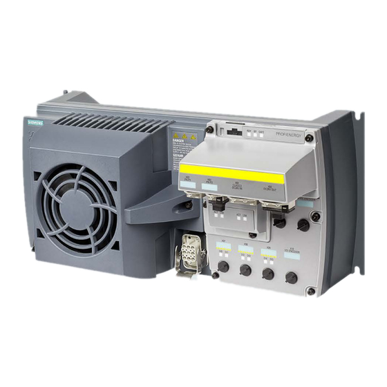
Introduction SINAMICS G120D converter Overview The SINAMICS G120D is a range of converters for controlling the speed of three-phase motors. The converter consists of two parts, the Control Unit and the Power Module. Table 2- 1 Control Units of the SINAMICS G120D converter... - Page 16 Introduction 2.1 SINAMICS G120D converter Table 2- 2 PM250D Power Modules for the SINAMICS G120D converter Frame Rated output Rated output Article number size power current based on High Overload (HO) 0.75 kW 2.2 A 6SL3525-0PE17-5AA1 1.5 kW 4.1 A 6SL3525-0PE21-5AA1 3.0 kW...
-
Page 17: Commissioning Tools
Introduction 2.2 Commissioning tools Commissioning tools Image 2-1 Commissioning tools - PC or IOP Handheld Kit SINAMICS G120D converter Getting Started, 07/2016, FW V4.7 SP6, A5E38556189B AA... - Page 18 Connection cable (3 m) between PC and converter: Article number 6SL3255-0AA00-2CA0 You obtain STARTER and Startdrive on a DVD: ● STARTER: Article number 6SL3072-0AA00-0AG0 ● Startdrive: Article number 6SL3072-4CA02-1XG0 STARTER and Startdrive download: ● STARTER Download (http://support.automation.siemens.com/WW/view/en/26233208) ● Startdrive (http://support.automation.siemens.com/WW/view/en/68034568) Help regarding operation: ● STARTER videos (http://www.automation.siemens.com/mcms/mc-drives/en/low-voltage- inverter/sinamics-g120/videos/Pages/videos.aspx)
-
Page 19: Installation
TN and TT mains supplies. The CU is fitted to the PM as shown in the diagram below. Image 3-1 Fitting the Control Unit to the Power Module SINAMICS G120D converter Getting Started, 07/2016, FW V4.7 SP6, A5E38556189B AA... -
Page 20: Drill Pattern Sinamics G120D
Installation 3.2 Drill pattern SINAMICS G120D Drill pattern SINAMICS G120D Drill pattern and dimensions The inverter has an identical drill pattern for all frame sizes. The drill pattern, depth and tightening torques are shown in the diagram below. Image 3-2... - Page 21 Installation 3.2 Drill pattern SINAMICS G120D Mounting orientation Mount the converter on a table or on a wall. The minimum clearance distances are as follows: ● Side-by-side - no clearance distance is required ● Above and below the inverter 150 mm (5.9 inches).
-
Page 22: Overview Of The Interfaces
Mains supply connection nation switch for PROFIBUS ⑦ ⑭ Digital outputs 0 and 1 with status LED Motor, brake and temperature sensor con- nections Image 3-4 Interfaces on the converter variants SINAMICS G120D converter Getting Started, 07/2016, FW V4.7 SP6, A5E38556189B AA... -
Page 23: Protective Conductor
Protective conductor for line feeder cables ② Protective conductor for inverter line feeder cables ③ Protective conductor between PE and the electrical cabinet ④ Protective conductor for motor feeder cables SINAMICS G120D converter Getting Started, 07/2016, FW V4.7 SP6, A5E38556189B AA... - Page 24 – The protective conductor consists of two conductors with the same cross-section. ● When connecting a multi-conductor cable using an industrial plug connector according to EN 60309, the protective conductor must have a cross-section of ≥ 2.5 mm² Cu. SINAMICS G120D converter Getting Started, 07/2016, FW V4.7 SP6, A5E38556189B AA...
-
Page 25: Grounding Converter And Motor
● Ground the connector as shown in the diagram above (grounding the converter). Although the line and motor connectors are of a different type, the principle of grounding them is the same. ● If possible, ground the motor housing. SINAMICS G120D converter Getting Started, 07/2016, FW V4.7 SP6, A5E38556189B AA... -
Page 26: Basic Emc Rules
● Route particularly sensitive signal cables, such as setpoint and actual value cables, with optimum shield bonding at both ends and without any interruptions of the shield. ● Ground spare wires for signal and data cables at both ends. SINAMICS G120D converter Getting Started, 07/2016, FW V4.7 SP6, A5E38556189B AA... -
Page 27: Connections And Interference Suppression
(RC elements or varistors for AC currentoperated coils, and freewheeling diodes for DC current-operated coils). The interference suppressors must be connected directly on each coil. SINAMICS G120D converter Getting Started, 07/2016, FW V4.7 SP6, A5E38556189B AA... -
Page 28: Equipotential Bonding
● Use a short grounding connection from the PE terminal on the inverter to the metal frame. The following figure illustrates all grounding and high-frequency equipotential bonding measures using an example. SINAMICS G120D converter Getting Started, 07/2016, FW V4.7 SP6, A5E38556189B AA... - Page 29 Grounding and high-frequency equipotential bonding measures in the drive system and in the plant You find further information on the rules for EMC compliant installation on the Internet: http://support.automation.siemens.com/WW/view/de/60612658 (http://support.automation.siemens.com/WW/view/en/60612658) SINAMICS G120D converter Getting Started, 07/2016, FW V4.7 SP6, A5E38556189B AA...
-
Page 30: Branch Circuit Protection Of Individual Inverters
10 A 1.5 kW 6SL3525-0PE21-5AA1 3 kW 6SL3525-0PE23-0AA1 3NA3805 3RV2011-4AA10 16 A 4 kW 6SL3525-0PE24-0AA1 3NA3807 3RV2021-4BA10 20 A 5.5 kW 6SL3525-0PE25-5AA1 7.5 kW 6SL3525-0PE27-5AA1 3NA3812 3RV2021-4PA10 32 A SINAMICS G120D converter Getting Started, 07/2016, FW V4.7 SP6, A5E38556189B AA... - Page 31 DIVQ Type E combination motor controller (designation according to the UL standard - is NKJH available as SIEMENS circuit breaker) Table 3- 4 Branch circuit protection with non-semiconductor fuses of Classes J, T, CC, G or CF (UL Category JDDZ)
- Page 32 LGG… or CED6… DIVQ 60 A 65 kA, 480 V 3AC 3RV1031-4EA… NKJH 32 A 65 kA, 480Y/277 V AC 3RV2031-4EA… NKJH 32 A 65 kA, 480Y/277 V AC SINAMICS G120D converter Getting Started, 07/2016, FW V4.7 SP6, A5E38556189B AA...
-
Page 33: Branch Circuit Protection Of Multiple Inverters
If it is precluded that all of the inverters of a group operate simultaneously, it is permissible to form larger inverter groups on one 400-V branch circuit. The sum of the input currents of all inverters must always be less than 24 A. SINAMICS G120D converter Getting Started, 07/2016, FW V4.7 SP6, A5E38556189B AA... - Page 34 Fuses of any manufacturer with faster tripping characteristic than class RK5, e.g. JDDZ class J, T, CC, G, or CF SIEMENS circuit breaker DIVQ Intrinsically safe SIEMENS circuit breaker NKJH Table 3- 8 Branch circuit protection with non-semiconductor fuses of Classes J, T, CC, G or CF (UL Category Code JDDZ) Max.
-
Page 35: Connections And Cables
If you don't need the switching of 2L+ power supply, then both the switched as well as the non-switched 24 V may come from the same supply. SINAMICS G120D converter Getting Started, 07/2016, FW V4.7 SP6, A5E38556189B AA... - Page 36 Installation 3.11 Connections and cables Image 3-10 CU240D-2 PROFIBUS connectors SINAMICS G120D converter Getting Started, 07/2016, FW V4.7 SP6, A5E38556189B AA...
- Page 37 Installation 3.11 Connections and cables Image 3-11 CU240D-2 PROFINET connectors SINAMICS G120D converter Getting Started, 07/2016, FW V4.7 SP6, A5E38556189B AA...
- Page 38 Installation 3.11 Connections and cables Image 3-12 CU240D-2 PROFINET Push-Pull connectors SINAMICS G120D converter Getting Started, 07/2016, FW V4.7 SP6, A5E38556189B AA...
- Page 39 Installation 3.11 Connections and cables Image 3-13 CU240D-2 PROFINET FO connectors SINAMICS G120D converter Getting Started, 07/2016, FW V4.7 SP6, A5E38556189B AA...
- Page 40 Installation 3.11 Connections and cables Image 3-14 CU250D-2 PROFIBUS connectors SINAMICS G120D converter Getting Started, 07/2016, FW V4.7 SP6, A5E38556189B AA...
- Page 41 Installation 3.11 Connections and cables Image 3-15 CU250D-2 PROFINET connectors SINAMICS G120D converter Getting Started, 07/2016, FW V4.7 SP6, A5E38556189B AA...
- Page 42 Installation 3.11 Connections and cables Image 3-16 CU250D-2 PROFINET Push-Pull connectors SINAMICS G120D converter Getting Started, 07/2016, FW V4.7 SP6, A5E38556189B AA...
- Page 43 Installation 3.11 Connections and cables Image 3-17 G120D CU250D-2 PROFINET FO connectors SINAMICS G120D converter Getting Started, 07/2016, FW V4.7 SP6, A5E38556189B AA...
- Page 44 Operating the converter on an inappropriate supply system can cause damage to the converter and other loads. • Only operate the converter on supply systems with V ≤ 1%. Image 3-18 PM250D connectors SINAMICS G120D converter Getting Started, 07/2016, FW V4.7 SP6, A5E38556189B AA...
- Page 45 The detailed specifications for the cables, connectors and tools required to manufacture the necessary cables for the SINAMICS G120D are listed in the following tables. The connections that are detailed in this section relate to the physical connections that exist on the Inverter.
- Page 46 30 m (98 ft) Encoder Screened 30 m (98 ft) The motor, temperature sensor and motor holding brake are connected through a hybrid cable to the inverter using a Harting connector. SINAMICS G120D converter Getting Started, 07/2016, FW V4.7 SP6, A5E38556189B AA...
- Page 47 Factory settings of the inputs and outputs of the control unit CU240D-2 In the factory settings, the fieldbus interface of the inverter is not active. Image 3-19 Factory settings of the control units CU240D-2 SINAMICS G120D converter Getting Started, 07/2016, FW V4.7 SP6, A5E38556189B AA...
- Page 48 The factory setting of the inputs and outputs described above corresponds to the default setting 7 (switchover between fieldbus and a jog using DI 3). Default settings of inputs and outputs (CU240D-2) (Page 49) SINAMICS G120D converter Getting Started, 07/2016, FW V4.7 SP6, A5E38556189B AA...
-
Page 49: Default Settings Of Inputs And Outputs (Cu240D-2)
Fixed speed setpoint 1: p1001, fixed speed setpoint 2: p1002, fixed speed setpoint active: r1024 Speed setpoint (main setpoint): p1070[0] = 1024 DI 0 and DI 1 = high: the inverter adds the two fixed speed setpoints. SINAMICS G120D converter Getting Started, 07/2016, FW V4.7 SP6, A5E38556189B AA... - Page 50 Several of the DI 0, DI 1, DI 4, and DI 5 = high: the inverter adds the corresponding fixed speed set- points. Default setting 4: "Conveyor system with fieldbus" DO 0: p0730, DO 1: p0731 Speed setpoint (main setpoint): p1070[0] = 2050[1] SINAMICS G120D converter Getting Started, 07/2016, FW V4.7 SP6, A5E38556189B AA...
- Page 51 Speed setpoint (main setpoint): p1070[0] = 2050[1] Default setting 6: "Fieldbus with Extended Safety" DO 0: p0730, DO 1: p0731 DI 0: r0722.0, …, DI 5: r0722.5 Speed setpoint (main setpoint): p1070[0] = 2050[1] SINAMICS G120D converter Getting Started, 07/2016, FW V4.7 SP6, A5E38556189B AA...
- Page 52 DI 0: r0722.0, …, DI 3: r0722.3 Speed setpoint (main setpoint): p1070[0] = 2050[1] Jog 1 speed setpoint: p1058, factory setting: 150 rpm Jog 2 speed setpoint: p1059, factory setting: -150 rpm SINAMICS G120D converter Getting Started, 07/2016, FW V4.7 SP6, A5E38556189B AA...
- Page 53 Default setting 9: "Standard I/O with MOP" DO 0: p0730, DO 1: p0731 DI 0: r0722.0, …, DI 3: r0722.3 Motorized potentiometer, setpoint after the ramp-function generator r1050 Speed setpoint (main setpoint): p1070[0] = 1050 SINAMICS G120D converter Getting Started, 07/2016, FW V4.7 SP6, A5E38556189B AA...
- Page 54 Default setting 13: "Standard I/O with analog setpoint and safety" DO 0: p0730, DO 1: p0731 DI 0: r0722.0, …, DI 5: r0722.5 AI 0: r0755[0] Speed setpoint (main setpoint): p1070[0] = 755[0] SINAMICS G120D converter Getting Started, 07/2016, FW V4.7 SP6, A5E38556189B AA...
- Page 55 DO 0: p0730, DO 1: p0731 DI 0: r0722.0, …, DI 5: r0722.5 Motorized potentiometer, setpoint after the ramp-function generator r1050 Speed setpoint (main setpoint): p1070[0] = 2050[1], p1070[1] = 1050 SINAMICS G120D converter Getting Started, 07/2016, FW V4.7 SP6, A5E38556189B AA...
- Page 56 DO 0: p0730, DO 1: p0731 DI 0: r0722.0, …, DI 5: r0722.5 p2081[0] = r0722.0, …, p2081[5] = r0722.5 p0730 = r2094.0, p0731 = r2094.1 Speed setpoint (main setpoint): p1070[0] = 2050[1] SINAMICS G120D converter Getting Started, 07/2016, FW V4.7 SP6, A5E38556189B AA...
- Page 57 = r2094.0, p0731 = r2094.1 Speed setpoint (main setpoint): p1070[0] = 2050[1] Default setting 26: "EPOS without fieldbus" Factory setting DO 0: p0730, DO 1: p0731 DI 0: r0722.0, …, DI 5: r0722.5 SINAMICS G120D converter Getting Started, 07/2016, FW V4.7 SP6, A5E38556189B AA...
-
Page 58: Settings Profibus Dp Address With Dip Switches
The external 24 V power supply must be switched off before the DIP switch settings are changed. DIP switch setting changes do not take effect until the Control Unit has been powered-up again. SINAMICS G120D converter Getting Started, 07/2016, FW V4.7 SP6, A5E38556189B AA... -
Page 59: Connecting The Profinet Interface
The screen of the PROFINET cable must be connected with the protective earth. The solid copper core must not be scored when the insulation is removed from the core ends. SINAMICS G120D converter Getting Started, 07/2016, FW V4.7 SP6, A5E38556189B AA... - Page 60 Installation 3.14 Connecting the PROFINET interface SINAMICS G120D converter Getting Started, 07/2016, FW V4.7 SP6, A5E38556189B AA...
-
Page 61: Commissioning
Commissioning Default settings for the SINAMICS G120D Factory default settings The inverter system is shipped from the factory as a Control Unit and a Power Module. Without any parameterization or after a factory reset, the inverter can be operated without... -
Page 62: Commissioning With The Iop
● Optical Cable - order number: 3RK1922-2BP00 Image 4-1 CU240D-2 and CU250D-2 Optical Interfaces Basic commissioning wizard The Basic Commissioning wizard detailed below is for Control Units with version 4.4 software or higher. SINAMICS G120D converter Getting Started, 07/2016, FW V4.7 SP6, A5E38556189B AA... - Page 63 Select the correct frequency for your Inverter and at- tached motor. The use of the 87 Hz characteristic allows the motor to operate at 1.73 times of its normal speed. SINAMICS G120D converter Getting Started, 07/2016, FW V4.7 SP6, A5E38556189B AA...
- Page 64 10. Input the correct Power Rating from the motor rating plate. 11. Input the correct Motor Speed from the motor rating plate. This value is given in RPM. SINAMICS G120D converter Getting Started, 07/2016, FW V4.7 SP6, A5E38556189B AA...
- Page 65 17. Set the Ramp Up time in seconds. This is the time the Inverter/motor system will take from being given the run command, to reaching the selected motor speed. SINAMICS G120D converter Getting Started, 07/2016, FW V4.7 SP6, A5E38556189B AA...
- Page 66 Inverter memory. The loca- tion of safe data is assigned using the "Parameter sav- ing mode" function in "Parameter settings" in "Menu". The basic commissioning of your converter is finished. SINAMICS G120D converter Getting Started, 07/2016, FW V4.7 SP6, A5E38556189B AA...
-
Page 67: Commissioning The Application
When used in conjunction with the various wiring diagrams contained within the IOP Operating Instructions, the application can be quickly and easily commissioned. Image 4-2 Example of IOP Wizards and Inverter wiring diagrams SINAMICS G120D converter Getting Started, 07/2016, FW V4.7 SP6, A5E38556189B AA... -
Page 68: Reset Parameters To Factory Settings
To reset parameters that relate to fail-safe functions an additional parameter reset with P0970 = 5 must be performed. This parameter reset is password protected. In case of a parameter reset with P0970 = 5 an acceptance test necessary. SINAMICS G120D converter Getting Started, 07/2016, FW V4.7 SP6, A5E38556189B AA... -
Page 69: Troubleshooting And Further Information
Check the module parameters and recommission if necessary. F01033 Unit switchover: Reference param- Set the value of the reference parameter not equal to 0.0 (p0304, p0305, eter value invalid p0310, p0596, p2000, p2001, p2002, p2003, r2004). SINAMICS G120D converter Getting Started, 07/2016, FW V4.7 SP6, A5E38556189B AA... - Page 70 Make sure that the sensor is connected correctly. Check the parameterization (p0601). Deactivate the temperature sensor fault (p0607 = 0). F07086 Unit switchover: Parameter limit Check the adapted parameter values and if required correct. F07088 violation SINAMICS G120D converter Getting Started, 07/2016, FW V4.7 SP6, A5E38556189B AA...
- Page 71 • Mechanical overload? • Other possible causes: Connecting cable, motor/drive converter incorrect (phase missing, • interchanged). When selecting motor identification, select tracking mode (BI: • p2655[0] = 1 signal). SINAMICS G120D converter Getting Started, 07/2016, FW V4.7 SP6, A5E38556189B AA...
- Page 72 The actual setpoint velocity is greater than the parameterized maximum velocity (p2571), and is therefore limited. Remedy: Check the entered setpoint velocity. • Reduce the velocity override (CI: p2646). • Increase the maximum velocity (p2571). • SINAMICS G120D converter Getting Started, 07/2016, FW V4.7 SP6, A5E38556189B AA...
- Page 73 Traversing block has illegal task Correct the task parameter in the traversing block. parameters A07468 Traversing block jump target does Correct the traversing block. • not exist Add the missing traversing block. • SINAMICS G120D converter Getting Started, 07/2016, FW V4.7 SP6, A5E38556189B AA...
- Page 74 (BI: p2640) and re-start motion. A07487 Reject traversing task missing Connect a "1" signal at the binector input "do not reject traversing task/reject traversing task" (BI: p2641) and re-start motion. SINAMICS G120D converter Getting Started, 07/2016, FW V4.7 SP6, A5E38556189B AA...
- Page 75 Reduce the frequency of the measuring pulses at the measuring • probe. A07581 Position actual value processing Check the encoder for the actual position value processing. A07582 error SINAMICS G120D converter Getting Started, 07/2016, FW V4.7 SP6, A5E38556189B AA...
- Page 76 The signal for "external alarm 1" has been triggered. A07851 Parameters p2112, p2116 and p2117 determine the signal sources for A07852 the external alarm 1… 3. Remedy: Rectify the cause of these alarms. SINAMICS G120D converter Getting Started, 07/2016, FW V4.7 SP6, A5E38556189B AA...
- Page 77 Receive configuration data not valid A08526 No cyclic connection Activate the controller with cyclic operation. • Check the parameters "Name of Station" and "IP of Station" (r61000, • r61001). SINAMICS G120D converter Getting Started, 07/2016, FW V4.7 SP6, A5E38556189B AA...
- Page 78 Set the rounding times (p1130, p1136). Activate the DC link voltage controller (p1240, p1280). Check the line voltage (p0210). Check the line phases. F30003 DC-link voltage undervoltage Check the line voltage (p0210). SINAMICS G120D converter Getting Started, 07/2016, FW V4.7 SP6, A5E38556189B AA...
- Page 79 For a signal output above a speed threshold, reduce the filter time • (p0438). F31118 Speed difference outside tolerance For an HTL/TTL encoder, the speed difference has exceeded the value in SINAMICS G120D converter Getting Started, 07/2016, FW V4.7 SP6, A5E38556189B AA...
- Page 80 (r0483) that can no longer be represented within 32 bits. Remedy: Check the encoder data. For further information, please refer to the List Manual. Manuals for the converter (Page 83) SINAMICS G120D converter Getting Started, 07/2016, FW V4.7 SP6, A5E38556189B AA...
-
Page 81: Status Led Overview
● Input and Output status ● Safety-Integrated status The location of the various LEDs on the Control Unit are shown in the figure below. Image 5-1 Status LED locations SINAMICS G120D converter Getting Started, 07/2016, FW V4.7 SP6, A5E38556189B AA... - Page 82 Link inactive with no data transfer Table 5- 7 Description of Digital Input and Output LEDs DI / DO Description of function Input/Output connected and working Input/Output not connected or has stopped working SINAMICS G120D converter Getting Started, 07/2016, FW V4.7 SP6, A5E38556189B AA...
-
Page 83: Manuals For The Converter
Handbücher mit weiterführender Information zum Download: ● Getting Started SINAMICS G120D (https://support.industry.siemens.com/cs/ww/en/view/109477364) Installing and commissioning the inverter. ● Operating instructions SINAMICS G120D with CU240D-2 (https://support.industry.siemens.com/cs/ww/en/view/109477366) Installing, commissioning and operating the inverter. Advanced commissioning. Technical data. ● Operating instructions SINAMICS G120D with CU250D-2 (https://support.industry.siemens.com/cs/ww/en/view/109477365)
Need help?
Do you have a question about the SINAMICS G120D and is the answer not in the manual?
Questions and answers