Siemens SINAMICS G120D Getting Started
Distributed converter, control units with encoder evaluation
Hide thumbs
Also See for SINAMICS G120D:
- List manual (910 pages) ,
- Operating instructions manual (398 pages) ,
- Original instructions manual (382 pages)
Table of Contents
Advertisement
Quick Links
Advertisement
Table of Contents

Related Manuals for Siemens SINAMICS G120D


Summary of Contents for Siemens SINAMICS G120D
- Page 3 Fundamental safety ___________________ SINAMICS G120D converter with control instructions units CU240D-2 and CU250D-2 ___________________ Introduction ___________________ Installation SINAMICS ___________________ Commissioning SINAMICS G120D ___________________ SINAMICS G120D converter with Troubleshooting control units CU240D-2 and CU250D-2 Getting Started Edition 04/2014, firmware V4.7 04/2014, FW V4.7...
- Page 4 Note the following: WARNING Siemens products may only be used for the applications described in the catalog and in the relevant technical documentation. If products and components from other manufacturers are used, these must be recommended or approved by Siemens. Proper transport, storage, installation, assembly, commissioning, operation and maintenance are required to ensure that the products operate safely and without any problems.
-
Page 5: Table Of Contents
Reset Parameters to Factory Settings ..................54 Troubleshooting ............................ 55 List of alarms and faults ....................... 55 Status LED overview ........................61 Further information ........................63 SINAMICS G120D converter with control units CU240D-2 and CU250D-2 Getting Started, 04/12014, FW V4.7, A5E34262374B AA... - Page 6 7. Use a card reader and load the file to a PC. You have then transferred the OSS license terms from the inverter to a PC. SINAMICS G120D converter with control units CU240D-2 and CU250D-2 Getting Started, 04/12014, FW V4.7, A5E34262374B AA...
-
Page 7: Fundamental Safety Instructions
• Only use power supplies that provide SELV (Safety Extra Low Voltage) or PELV- (Protective Extra Low Voltage) output voltages for all connections and terminals of the electronics modules. SINAMICS G120D converter with control units CU240D-2 and CU250D-2 Getting Started, 04/12014, FW V4.7, A5E34262374B AA... - Page 8 • Ensure that smoke can only escape via controlled and monitored paths. SINAMICS G120D converter with control units CU240D-2 and CU250D-2 Getting Started, 04/12014, FW V4.7, A5E34262374B AA...
- Page 9 • Check that the warning labels are complete based on the documentation. • Attach any missing warning labels to the components, in the national language if necessary. • Replace illegible warning labels. SINAMICS G120D converter with control units CU240D-2 and CU250D-2 Getting Started, 04/12014, FW V4.7, A5E34262374B AA...
- Page 10 • Protect the parameterization (parameter assignments) against unauthorized access. • Respond to possible malfunctions by applying suitable measures (e.g. EMERGENCY STOP or EMERGENCY OFF). SINAMICS G120D converter with control units CU240D-2 and CU250D-2 Getting Started, 04/12014, FW V4.7, A5E34262374B AA...
-
Page 11: Safety Instructions For Electromagnetic Fields (Emf)
– Wearing ESD shoes or ESD grounding straps in ESD areas with conductive flooring • Only place electronic components, modules or devices on conductive surfaces (table with ESD surface, conductive ESD foam, ESD packaging, ESD transport container). SINAMICS G120D converter with control units CU240D-2 and CU250D-2 Getting Started, 04/12014, FW V4.7, A5E34262374B AA... -
Page 12: Industrial Security
Siemens recommends strongly that you regularly check for product updates. For the secure operation of Siemens products and solutions, it is necessary to take suitable preventive action (e.g. cell protection concept) and integrate each component into a holistic, state-of-the-art industrial security concept. -
Page 13: Residual Risks Of Power Drive Systems
Inverters of the Open Type/IP20 degree of protection must be installed in a metal control cabinet (or protected by another equivalent measure) such that contact with fire inside and outside the inverter is not possible. SINAMICS G120D converter with control units CU240D-2 and CU250D-2 Getting Started, 04/12014, FW V4.7, A5E34262374B AA... - Page 14 For more information about residual risks of the components in a drive system, see the relevant sections in the technical user documentation. SINAMICS G120D converter with control units CU240D-2 and CU250D-2 Getting Started, 04/12014, FW V4.7, A5E34262374B AA...
-
Page 15: Introduction
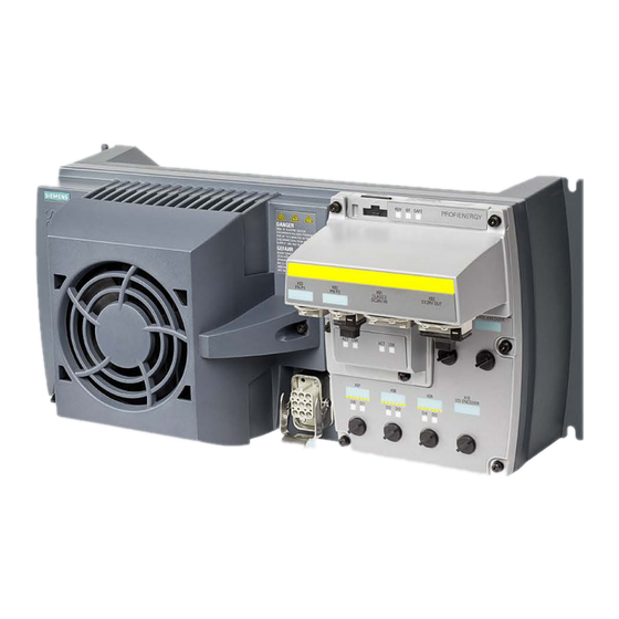
Introduction SINAMICS G120D converter Overview The SINAMICS G120D is a range of converters for controlling the speed of three-phase motors. The converter consists of two parts, the Control Unit and the Power Module. Table 2- 1 Control Units of the SINAMICS G120D converter... - Page 16 1.5 kW 4.1 A 6SL3525-0PE21-5AA1 3.0 kW 7.7 A 6SL3525-0PE23-0AA1 4.0 kW 10.2 A 6SL3525-0PE24-0AA1 5.5 kW 13.2 A 6SL3525-0PE25-5AA1 7.5 kW 19.0 A 6SL3525-0PE27-5AA1 SINAMICS G120D converter with control units CU240D-2 and CU250D-2 Getting Started, 04/12014, FW V4.7, A5E34262374B AA...
-
Page 17: Commissioning Tools
Introduction 2.2 Commissioning tools Commissioning tools Figure 2-1 Commissioning tools - PC or IOP Handheld Kit SINAMICS G120D converter with control units CU240D-2 and CU250D-2 Getting Started, 04/12014, FW V4.7, A5E34262374B AA... - Page 18 You obtain STARTER on a DVD software) (Order number: 6SL3072- 0AA00-0AG0) and it can be downloaded: STARTER Download (http://support.automation.sieme ns.com/WW/view/en/26233208) PC Connection Kit Comprising USB cable (3 m). 6SL3255-0AA00-2CA0 SINAMICS G120D converter with control units CU240D-2 and CU250D-2 Getting Started, 04/12014, FW V4.7, A5E34262374B AA...
-
Page 19: Installation
TN and TT mains supplies. The CU is fitted to the PM as shown in the diagram below. Figure 3-1 Fitting the Control Unit to the Power Module SINAMICS G120D converter with control units CU240D-2 and CU250D-2 Getting Started, 04/12014, FW V4.7, A5E34262374B AA... -
Page 20: Drill Pattern Sinamics G120D
The inverter has an identical drill pattern for all frame sizes. The drill pattern, depth and tightening torques are shown in the diagram below. Figure 3-2 SINAMICS G120D drill pattern SINAMICS G120D converter with control units CU240D-2 and CU250D-2 Getting Started, 04/12014, FW V4.7, A5E34262374B AA... - Page 21 Additionally you have to reduce the converter output current to 80 % of rated converter current. If the output current derating adversely affects the application, you have to use an converter of the next highest power rating. SINAMICS G120D converter with control units CU240D-2 and CU250D-2 Getting Started, 04/12014, FW V4.7, A5E34262374B AA...
-
Page 22: Overview Of The Interfaces
PROFIBUS ⑦ ⑭ Digital outputs 0 and 1 with status LED Motor, brake and temperature sensor connections Figure 3-4 Interfaces on the converter variants SINAMICS G120D converter with control units CU240D-2 and CU250D-2 Getting Started, 04/12014, FW V4.7, A5E34262374B AA... -
Page 23: Electrical Data
Remove the rectifier module and connect the brake output of the converter directly to the brake coil. The UL approved current rating for the brake output is 600 mA. SINAMICS G120D converter with control units CU240D-2 and CU250D-2 Getting Started, 04/12014, FW V4.7, A5E34262374B AA... -
Page 24: Basic Emc Rules
● Use only metallic or metallized connector housings for shielded data cables (e. g. PROFIBUS cables). SINAMICS G120D converter with control units CU240D-2 and CU250D-2 Getting Started, 04/12014, FW V4.7, A5E34262374B AA... -
Page 25: Connections And Cables
If you don't need the switching of 2L+ power supply, then both the switched as well as the non-switched 24 V may come from the same supply. SINAMICS G120D converter with control units CU240D-2 and CU250D-2 Getting Started, 04/12014, FW V4.7, A5E34262374B AA... - Page 26 Installation 3.6 Connections and cables Figure 3-5 CU240D-2 PROFIBUS connectors SINAMICS G120D converter with control units CU240D-2 and CU250D-2 Getting Started, 04/12014, FW V4.7, A5E34262374B AA...
- Page 27 Installation 3.6 Connections and cables Figure 3-6 CU240D-2 PROFINET connectors SINAMICS G120D converter with control units CU240D-2 and CU250D-2 Getting Started, 04/12014, FW V4.7, A5E34262374B AA...
- Page 28 Installation 3.6 Connections and cables Figure 3-7 CU240D-2 PROFINET Push-Pull connectors SINAMICS G120D converter with control units CU240D-2 and CU250D-2 Getting Started, 04/12014, FW V4.7, A5E34262374B AA...
- Page 29 Installation 3.6 Connections and cables Figure 3-8 CU240D-2 PROFINET FO connectors SINAMICS G120D converter with control units CU240D-2 and CU250D-2 Getting Started, 04/12014, FW V4.7, A5E34262374B AA...
- Page 30 Installation 3.6 Connections and cables Figure 3-9 CU250D-2 PROFIBUS connectors SINAMICS G120D converter with control units CU240D-2 and CU250D-2 Getting Started, 04/12014, FW V4.7, A5E34262374B AA...
- Page 31 Installation 3.6 Connections and cables Figure 3-10 CU250D-2 PROFINET connectors SINAMICS G120D converter with control units CU240D-2 and CU250D-2 Getting Started, 04/12014, FW V4.7, A5E34262374B AA...
- Page 32 Installation 3.6 Connections and cables Figure 3-11 CU250D-2 PROFINET Push-Pull connectors SINAMICS G120D converter with control units CU240D-2 and CU250D-2 Getting Started, 04/12014, FW V4.7, A5E34262374B AA...
- Page 33 Installation 3.6 Connections and cables Figure 3-12 G120D CU250D-2 PROFINET FO connectors SINAMICS G120D converter with control units CU240D-2 and CU250D-2 Getting Started, 04/12014, FW V4.7, A5E34262374B AA...
- Page 34 The detailed specifications for the cables, connectors and tools required to manufacture the necessary cables for the SINAMICS G120D are listed in the following tables. The connections that are detailed in this section relate to the physical connections that exist on the Inverter.
- Page 35 5.50 kW … 7.50 kW 6 mm (10 AWG) 3RK1911-2BE30 Order motor connector including temperature sensor and motor holding brake via solution partner: Solution partner (https://www.automation.siemens.com/solutionpartner/partnerfinder/Partner- Finder.aspx?lang=en) SINAMICS G120D converter with control units CU240D-2 and CU250D-2 Getting Started, 04/12014, FW V4.7, A5E34262374B AA...
- Page 36 30 m (98 ft) The motor, temperature sensor and motor holding brake are connected through a hybrid cable to the inverter using a Harting connector. SINAMICS G120D converter with control units CU240D-2 and CU250D-2 Getting Started, 04/12014, FW V4.7, A5E34262374B AA...
- Page 37 Factory settings of the inputs and outputs of the control unit CU240D-2 In the factory settings, the fieldbus interface of the inverter is not active. Figure 3-14 Factory settings of the control units CU240D-2 SINAMICS G120D converter with control units CU240D-2 and CU250D-2 Getting Started, 04/12014, FW V4.7, A5E34262374B AA...
- Page 38 The factory setting of the terminals described above corresponds to the default setting 7 (switchover between fieldbus and a jog using DI 3). See also: Default settings of inputs and outputs (Page 39). SINAMICS G120D converter with control units CU240D-2 and CU250D-2 Getting Started, 04/12014, FW V4.7, A5E34262374B AA...
-
Page 39: Default Settings Of Inputs And Outputs
Default setting 8: Motorized potentiometer (MOP) with safety Factory setting function PROFIdrive telegram 1 Fieldbus interface is not active. Fieldbus interface is not active. SINAMICS G120D converter with control units CU240D-2 and CU250D-2 Getting Started, 04/12014, FW V4.7, A5E34262374B AA... - Page 40 Default setting 26: Basic positioner via inputs and outputs; Default setting 27: Basic positioner via fieldbus factory settings The fieldbus interface is not active. PROFIdrive telegram 111 SINAMICS G120D converter with control units CU240D-2 and CU250D-2 Getting Started, 04/12014, FW V4.7, A5E34262374B AA...
-
Page 41: Settings Profibus Dp Address With Dip Switches
DIP switch Add to address Example 1: Address = 3 = 1 + 2 Example 2: Address = 88 = 8 + 16 + 64 SINAMICS G120D converter with control units CU240D-2 and CU250D-2 Getting Started, 04/12014, FW V4.7, A5E34262374B AA... -
Page 42: Connecting The Profinet Interface
● Ground the converter via the PE connection in the mains supply connector. ● Ground the connectors as shown in the diagram below. Figure 3-16 Grounding the line supply and motor connectors SINAMICS G120D converter with control units CU240D-2 and CU250D-2 Getting Started, 04/12014, FW V4.7, A5E34262374B AA... - Page 43 M25 x 1.5 20 … 13 16… 10 30 x 33 bg255mstri M32 x 1.5 25 … 20 20 … 13 36 x 39.5 bg232mstri SINAMICS G120D converter with control units CU240D-2 and CU250D-2 Getting Started, 04/12014, FW V4.7, A5E34262374B AA...
-
Page 44: Connections And Interference Suppression
3. Use a short grounding connection from the PE terminal on the inverter to the metal frame. The following figure illustrates all grounding and high-frequency equipotential bonding measures using an example. SINAMICS G120D converter with control units CU240D-2 and CU250D-2 Getting Started, 04/12014, FW V4.7, A5E34262374B AA... - Page 45 Grounding and high-frequency equipotential bonding measures in the drive system and in the plant For general rules for EMC compliant installation see also: http://support.automation.siemens.com/WW/view/de/60612658 (http://support.automation.siemens.com/WW/view/en/60612658) SINAMICS G120D converter with control units CU240D-2 and CU250D-2 Getting Started, 04/12014, FW V4.7, A5E34262374B AA...
-
Page 47: Commissioning
The Control Unit is intended to be control and operate the inverter utilizing the PROFIBUS or PROFINET interface. The PROFIBUS or PROFINET interface may be used to further configure and control the inverter as required. SINAMICS G120D converter with control units CU240D-2 and CU250D-2 Getting Started, 04/12014, FW V4.7, A5E34262374B AA... -
Page 48: Commissioning With The Iop
G120D Inverters; the order details of the necessary cable is given below. ● The IOP Handheld Kit - order number: 6SL3255-0AA00-4HA0. ● Optical Cable - order number: 3RK1922-2BP00 Figure 4-1 CU240D-2 and CU250D-2 Optical Interfaces SINAMICS G120D converter with control units CU240D-2 and CU250D-2 Getting Started, 04/12014, FW V4.7, A5E34262374B AA... - Page 49 Select the correct frequency for your Inverter and attached motor. The use of the 87 Hz characteristic allows the motor to operate at 1.73 times of its normal speed. SINAMICS G120D converter with control units CU240D-2 and CU250D-2 Getting Started, 04/12014, FW V4.7, A5E34262374B AA...
- Page 50 10. Input the correct Power Rating from the motor rating plate. 11. Input the correct Motor Speed from the motor rating plate. This value is given in RPM. SINAMICS G120D converter with control units CU240D-2 and CU250D-2 Getting Started, 04/12014, FW V4.7, A5E34262374B AA...
- Page 51 17. Set the Ramp Up time in seconds. This is the time the Inverter/motor system will take from being given the run command, to reaching the selected motor speed. SINAMICS G120D converter with control units CU240D-2 and CU250D-2 Getting Started, 04/12014, FW V4.7, A5E34262374B AA...
- Page 52 "Parameter saving mode" function in "Parameter settings" in "Menu". The basic commissioning of your converter is finished. SINAMICS G120D converter with control units CU240D-2 and CU250D-2 Getting Started, 04/12014, FW V4.7, A5E34262374B AA...
-
Page 53: Commissioning The Application
IOP Operating Instructions, the application can be quickly and easily commissioned. Figure 4-2 Example of IOP Wizards and Inverter wiring diagrams SINAMICS G120D converter with control units CU240D-2 and CU250D-2 Getting Started, 04/12014, FW V4.7, A5E34262374B AA... -
Page 54: Reset Parameters To Factory Settings
P0970 = 5 must be performed. This parameter reset is password protected. In case of a parameter reset with P0970 = 5 an acceptance test necessary. SINAMICS G120D converter with control units CU240D-2 and CU250D-2 Getting Started, 04/12014, FW V4.7, A5E34262374B AA... -
Page 55: Troubleshooting
Set the value of the reference parameter to a value other than 0.0 (p0304, parameter value invalid p0305, p0310, p0596, p2000, p2001, p2002, p2003, r2004). SINAMICS G120D converter with control units CU240D-2 and CU250D-2 Getting Started, 04/12014, FW V4.7, A5E34262374B AA... - Page 56 Make sure that the sensor is connected correctly. Check the parameterization (p0601). F07086 Unit switchover: Parameter limit Check the adapted parameter values and if required correct. F07088 violation SINAMICS G120D converter with control units CU240D-2 and CU250D-2 Getting Started, 04/12014, FW V4.7, A5E34262374B AA...
- Page 57 Make sure that the motor can rotate freely. • Check the torque limit: r1538 for a positive direction of rotation; r1539 for • a negative direction of rotation. SINAMICS G120D converter with control units CU240D-2 and CU250D-2 Getting Started, 04/12014, FW V4.7, A5E34262374B AA...
- Page 58 IP address, subnet mask or default gateway is not correct. • IP address or station name used twice in the network. • Station name contains invalid characters. • SINAMICS G120D converter with control units CU240D-2 and CU250D-2 Getting Started, 04/12014, FW V4.7, A5E34262374B AA...
- Page 59 I2t converter overload Check the rated currents of the motor and Power Module. Reduce current limit p0640. When operating with U/f characteristic: Reduce p1341. SINAMICS G120D converter with control units CU240D-2 and CU250D-2 Getting Started, 04/12014, FW V4.7, A5E34262374B AA...
- Page 60 "Shared Device" is activated (p8929 = 2). However, only the connection to a missing PROFINET controller is present. For further information, please refer to the List Manual. SINAMICS G120D converter with control units CU240D-2 and CU250D-2 Getting Started, 04/12014, FW V4.7, A5E34262374B AA...
-
Page 61: Status Led Overview
Figure 5-1 Status LED locations Explanation of status LEDs An explanation of the various states indicated by the LEDs are given in the tables below. SINAMICS G120D converter with control units CU240D-2 and CU250D-2 Getting Started, 04/12014, FW V4.7, A5E34262374B AA... - Page 62 Description of Digital Input and Output LEDs DI / DO Description of function Input/Output connected and working Input/Output not connected or has stopped working SINAMICS G120D converter with control units CU240D-2 and CU250D-2 Getting Started, 04/12014, FW V4.7, A5E34262374B AA...
-
Page 63: Further Information
Configuring the field busses. 6SL3298-0CA00-0MG0 • Busses List manual Complete list of parameters, alarms and faults. Graphic function block diagrams. Operating instructions - Description of operator panel SINAMICS G120D converter with control units CU240D-2 and CU250D-2 Getting Started, 04/12014, FW V4.7, A5E34262374B AA... - Page 64 Troubleshooting 5.3 Further information SINAMICS G120D converter with control units CU240D-2 and CU250D-2 Getting Started, 04/12014, FW V4.7, A5E34262374B AA...
Need help?
Do you have a question about the SINAMICS G120D and is the answer not in the manual?
Questions and answers