Burkert 8792 Operating Instructions Manual
Electropneumatic positioner
Hide thumbs
Also See for 8792:
- Operating instructions manual (246 pages) ,
- Quick start manual (57 pages) ,
- Supplement to operating instructions (28 pages)
Table of Contents
Advertisement
Advertisement
Chapters
Table of Contents
Troubleshooting

Related Manuals for Burkert 8792


Summary of Contents for Burkert 8792
- Page 1 Type 8792, 8793 Positioner Electropneumatic positioner Operating Instructions...
- Page 2 We reserve the right to make technical changes without notice. Technische Änderungen vorbehalten. Sous resérve de modification techniques. © 2009 Bürkert Werke GmbH & Co. KG Operating Instructions 0908/01_EN-en_00806089...
-
Page 3: Table Of Contents
Type 8792, 8793 Contents positioner typ 8792, 8793 able of conTenTs General InformatIon and Safety InStructIonS.....................7 Operating.Instructions.................................8 Authorized.use..................................9 Basic.Safety.Instructions..............................10 General.Information................................12 deScrIptIon of SyStem..................................15 Description.and.features.of.the.positioner......................16 Structure.of.the.positioner.............................20 Type.8792.with.position.controller.function......................22 Type.8793.with.process.controller.function......................26 Interfaces.of.the.positioner............................30 Technical.Data..................................31 10.. control and dISplay elementS, operatInG modeS....................35 11.. - Page 4 Type 8792, 8793 Contents Start-up and operatIon of the poSItIon controller type 8792............77 Starting.up.and.adjusting.the.position.controller....................79 19.. Operating.the.position.controller..........................85 20.. Configuring.the.auxiliary.functions..........................90 21.. Start-up and operatIon of the poSItIon controller type 8793............121 22.. Starting.up.and.adjusting.the.process.controller.................... 123 23.. Operation.of.the.process.controller........................145 24..
- Page 5 Type 8792, 8793 Contents Adjustment.rules.for.PID.Controllers........................213 45.. taBleS for cuStomer-SpecIfIc SettInGS........................217 46.. Table.for.Your.Settings.on.the.Position.Controller..................218 47.. Table.for.Your.Settings.on.the.Process.Controller.8793................219 maSter code......................................221 Master.cod.................................... 222 48.. english...
-
Page 6: Type
Type 8792, 8793 Contents english... -
Page 7: General Information And Safety Instructions
Type 8792, 8793 General Information and Safety Instructions onTenTs OPErATInG.InSTruCTIOnS.................................8 1.1.. Symbols.......................................8 AuThOrIzED.uSE....................................9 2.1.. restrictions....................................9 2.2.. Predictable.Misuse.................................9 BASIC.SAFETY.InSTruCTIOnS...............................10 GEnErAl.InFOrMATIOn................................12 4.1.. Scope.of.Supply...................................12 4.2.. Warranty....................................13 4.3.. Master.code....................................13 4.4.. Information.on.the.Internet.............................13 english... -
Page 8: Operating.instructions
Type 8792, 8793 Type 8792, 8793 General Information Safety Instructions OperaTing insTrucTiOns The operating instructions describe the entire life cycle of the device. Keep these instructions in a location which is easily accessible to every user and make these instructions available to every new owner of the device. -
Page 9: Authorized.use
If exporting the system/device, observe any existing restrictions. 2.2. predictable Misuse • The positioners Type 8792 and Type 8793 must not be used in areas where there is a risk of explosion. • Do not supply the medium connectors of the system with aggressive or flammable mediums. •... -
Page 10: Basic.safety.instructions
Type 8792, 8793 Type 8792, 8793 General Information Safety Instructions Basic safeTy insTrucTiOns These safety instructions do not make allowance for any • contingencies and events which may arise during the installation, operation and maintenance of the devices. • local safety regulations – the operator is responsible for observing these regulations, also with reference to the installation personnel. - Page 11 General Information Safety Instructions The positioners Type 8792 and Type 8793 were developed with due consideration given to the accepted safety rules and are state-of-the-art. Nevertheless, dangerous situations may occur. Failure to observe this operating manual and its operating instructions as well as unauthorized tampering...
-
Page 12: General.information
Generally the product package consists of: positioner, type 8792 / 8793 and the associated operating instructions We will provide you with attachment kits for push drives or swivel actuators as accessories. For the multipole version of the positioners we will provide you with cable connectors as accessories. -
Page 13: Warranty
This document contains no promise of guarantee. Please refer to our general terms of sales and delivery. The war- ranty is only valid if the positioners Type 8792 and Type 8793 are used as intended in accordance with the specified application conditions. - Page 14 Type 8792, 8793 General Information Safety Instructions english...
-
Page 15: Description Of System
5.1.1. Features ..............................16 5.1.2. Combination with valve types and mounting versions ..............17 5.1.3. Overview of the mounting options.......................18 5.2.. Designs.....................................19 5.2.1. Type 8792, positioner with position control function ..............19 5.2.2. Type 8793, positioner with process control function ..............19 STruCTurE.OF.ThE.POSITIOnEr............................20 6.1.. representation..................................20 6.2.. -
Page 16: Description.and.features.of.the.positioner
If there is a control difference, the electro-pneumatic control system corrects the actual position accordingly. 5.1.1. features Versions. • The positioner features either a position control function (Type 8792) or a process control function (Type 8793). Position.measuring.systems. • - internal high resolution conductive plastic potentiometer or - external non-contact, non-wearing position measuring system (remote). -
Page 17: Combination With Valve Types And Mounting Versions
In this design, no spring is installed in the actuator. Two basic device versions are offered for the positioner Type 8792 / 8793; they differ in the attachment option and in the position measuring system. -
Page 18: Overview Of The Mounting Options
Types 8792, 8793 Description of System 5.1.3. Overview of the mounting options Mounting on swivel drive Mounting with mounting bracket on a push actuator Remote mounting with mounting bracket Remote mounting with DIN rail Table 1: Overview of the mounting options English... -
Page 19: Designs
Types 8792, 8793 Description of System 5.2. designs 5.2.1. Type 8792, positioner with position control function The position of the actuator is regulated according to the position set-point value. The position set-point value is specified by an external uniform signal (or via field bus). 5.2.2. Type 8793, positioner with process control function The positioner Type 8793 also features a PID controller which, apart from actual position control, can also be used to implement process control (e.g. -
Page 20: Structure.of.the.positioner
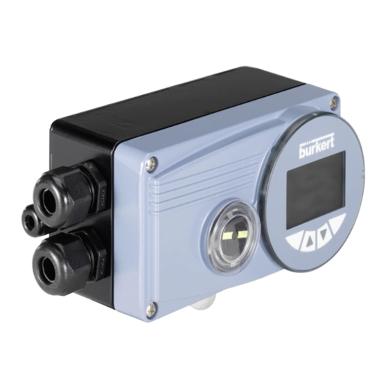
Description of System sTrucTure Of The pOsiTiOner The positioners Type 8792 and Type 8793 consist of the micro-processor controlled electronics, the position meas- uring system and the control system. The appliance is designed using three-wire technology. Operation of the positioner is controlled by four keys and a 128 x 64 dot matrix graphics display. -
Page 21: Function.diagram
6.2.1. diagram illustrating single-acting actuator The black lines in Fig. 2: specify the function of the position controller circuit in Type 8792. The grey part of the diagram indicates the additional function of the superimposed process control circuit in Type 8793. Compressed- Continuous.valve.with.. -
Page 22: Type.8792.With.position.controller.function
0. Z1 represents a disturbance variable. Valve opening Position set- Position Control system Continuous point value controller Solenoid valves valve Position measuring position control circuit system Fig. 3: Position control circuit in Type 8792 English... -
Page 23: Schematic.representation.of.the.position.control
Types 8792, 8793 Description of System 7.1. schematic representation of the position control Fig. 4: Schematic representation of position control English... -
Page 24: Properties.of.the.position.controller.software
Types 8792, 8793 Description of System 7.2. properties of the position controller software Position.controller.with.additional.function Additional.function Effect Sealing function Valve closes tight outside the control range. Specification of the value (in %), from which the actuator is completely CUTOFF deaerated (when 0%) or aerated (when 100%). Stroke limit... - Page 25 Types 8792, 8793 Description of System hierarchical.control.concept.for.easy.control.on.the.following.levels Additional.function Effect Process control On this level switch between AUTOMATIC and MANUAL mode. Configuration and Parameterization On this level specify certain basic functions during start- up and, if required, configure additional functions Table 3: Properties of the position controller software. Position controller with additional function; hierarchical control concept.
-
Page 26: Type.8793.With.process.controller.function
Types 8792, 8793 Description of System Type 8793 WiTh prOcess cOnTrOller funcTiOn If the positioner Type 8793 is operated with process controller function, the position control mentioned in chapter 7. becomes the subordinate auxiliary control circuit; this results in a cascade control. The process controller in the main control circuit of the positioner has a PID function. -
Page 27: Schematic.representation.of.process.control
Types 8792, 8793 Description of System 8.1. schematic representation of process control Fig. 6: Schematic representation of process control English... -
Page 28: Properties.of.the.position.controller.software
Types 8792, 8793 Description of System 8.2. properties of the position controller software Additional.function Effect Position.controller.with.additional.function Correction line to adjust the operating The process characteristic can be linearized characteristic CHARACT Sealing function Valve closes tight outside the control range. Specification of the value (in %), from which the actuator is completely CUTOFF deaerated (when 0%) or aerated (when 100%). - Page 29 Types 8792, 8793 Description of System Process.controller.with.the.following.setting.options Process controller PID - Process controller is activated P.CONTROL Adjustable parameters Parameterization of the process controller P.CONTROL - PARAMETER Proportional coefficient, reset time, hold-back time and operating point Scalable inputs Configuration of the process controller P.CONTROL - SETUP...
-
Page 30: Interfaces.of.the.positioner
Optional inputs and outputs are illustrated by dotted lines Fig. 7: Interfaces of the positioner The positioners Type 8792 and Type 8793 are 3-wire devices, i.e. the power (24 V DC) is supplied separately from the set-point value signal. * only for process controller Type 8793... -
Page 31: Technical.data
Types 8792, 8793 Description of System 10. Technical daTa 10.1. safety positions after failure of the electrical or pneumatic auxiliary power In single-acting actuators the safety position depends on the fluid connection of the drive to the working connec- tions A1 or A2 (see Fig. 8: and Fig. 9:) Safety.positions.after.failure.of.the.auxiliary. power Actuator.system... -
Page 32: Factory.settings.of.the.positioner
Types 8792, 8793 Description of System 10.2. factory settings of the positioner Function Factory setting Function Factory setting INPUT 4 – 20 mA X.CONTROL DBND 1.0% CHARACT linear KXopn (1) Values of X.TUNE determined KXcls (1) Values of X.TUNE determined DIR.CMD Rise After running SET.FACTORY: 1... -
Page 33: Specifications.of.the.positioner
(only if cables, plugs and sockets have been connected correctly) * If the positioner is used under IP 67 conditions, the ventilation filter (see Fig. 1:Structure, positioner type 8792 / 8793) must be removed and the exhaust air conducted into the dry area. -
Page 34: Pneumatic Data
Types 8792, 8793 Description of System Frequency: Measuring range 0 – 1000 Hz Input resistance 17 kΩ Resolution 1‰ of the measured value, Input signal > 300 mV Signal form Sine, rectangle, triangle Pt 100 Measuring range -20 – +220 °C, Resolution <... -
Page 35: Control And Display Elements, Operating Modes
Type 8792, 8793 control and display elements, operating modes onTenTs 11.. COnTrOl.AnD.DISPlAY.ElEMEnTS............................36 11.1.. Control.and.display.elements.of.the.positioner....................36 11.2.. Configuration.of.the.keys..............................37 11.3.. Information.on.the.display..............................38 OPErATInG.MODES..................................39 12.. 12.1.. Operating.state..................................39 12.2.. AuTOMATIC.Operating.State.for.Type.8792......................40 12.3.. AuTOMATIC.Operating.State.for.Type.8793......................41 12.4.. MAnuAl.operating.state..............................42 13.. OPErATInG.lEVElS..................................43 13.1.. Switching.between.the.operating.levels.........................43 english... -
Page 36: Control.and.display.elements
The following chapter describes the control and display elements of the positioner. Further information on the control of the positioner can be found in the chapters entitled “Installation”, “Start-up and operation of the position controller Type 8792” and “Start-up and operation of the position controller Type 8793”. 11.1. -
Page 37: 11.2. Configuration Of The Keys
Type 8792, 8793 Control and display elements, operating modes 11.2. configuration of the keys The assignment of the 4 keys on the control panel differs depending on the operating status (AUTOMATIC / MANUAL) or operating level (Operate process / Parameterization and Configuration) of the positioner. -
Page 38: Information.on.the.display
Type 8792, 8793 Control and display elements, operating modes 11.3. information on the display The following representation describes the information on the display: Display for AUTOMATIC mode: bar runs from left to right Description of the value Value Unit or percentage of the value Bar graph display of... -
Page 39: Operating.modes
Type 8792, 8793 Control and display elements, operating modes 12. OperaTing MOdes 12.1. Operating state The positioner has 2 operating states: AUTOMATIC and MANUAL mode. AUTOMATIC Normal control mode is implemented and monitored in AUTOMATIC operating state. (A bar runs along the upper edge of the display). -
Page 40: Automatic.operating.state.for.type.8792
Internal temperature in the housing of the positioner 20.0 TEMP (°C) MENU CMD INPUT Input signal for nominal position INPUT (0 – 5/10 V or 0/4 – 20 mA) MENU TEMP POS Table 11: Automatic Operating State for Type 8792 english... -
Page 41: Automatic.operating.state.for.type.8793
Automatic Operating State for Type 8793 If the P.CONTROL additional function is not active, the displays are represented as under Type 8792. * Here is indicated: - INPUT if the internal set-point value default is selected (P.CONTROL - SP-INPUT - internal). -
Page 42: Manual.operating.state
Type 8792, 8793 Control and display elements, operating modes 12.4. Manual operating state (no bar running along upper edge of display) In MANUAL operating state the valve can be opened and closed manually via the arrow keys. Meaning of the arrow keys in MANUAL operating state:... -
Page 43: Operating.levels
Type 8792, 8793 Control and display elements, operating modes 13. OperaTing levels The menu structure in the control module of the positioner contains 2 operating levels: level.1:. . Operate.process → Operating mode AUTOMATIC Process / Input data displayed → MANUAL Actuator opened and closed manually level.2:. - Page 44 Type 8792, 8793 Control and display elements, operating modes english...
-
Page 45: Installation
15.1.. Safety.instructions................................59 ElECTrICAl.COnnECTIOn.-.MulTI-POlE.PluG.VErSIOn..................61 16.. 16.1.. Type.8792.-.designation.of.the.circular.connectors..................61 16.2.. Connection.of.the.position.controller.Type.8792....................62 16.2.1. Input signals of the control centre (e.g. PLC) - M12, 8-pole plug ..........62 16.2.2. Output signals to the control centre (e.g. PLC) - M 12, 8-pole plug (required for analogue output option only) ..........................62... - Page 46 Type 8792, 8793 Installation 17.1.. Connection.board.of.the.positioner.with.screw-type.terminals..............66 17.2.. Terminal.Assignment.for.Cable.Gland.-.Position.Controller.Type.8792..........67 17.2.1. Input signals from the control centre (e.g. PLC) ................67 17.2.2. Output signals to the control centre (e.g. PLC) (required for Analogue output and/or Binary output option only) ..........................67 17.2.3. Operating voltage ............................68 17.2.4. Connecting the external position measuring system (for remote model only) ......68 17.3..
-
Page 47: Attachment.and.assembly
Type 8792, 8793 Installation 14. aTTachMenT and asseMBly The dimensions of the positioner and the different device versions can be found on the data sheet. 14.1. safety instructions: WarnInG! risk.of.injury.from.improper.installation! • Installation may be carried out by authorised technicians only and with the appropriate tools! risk.of.injury.from.unintentional.activation.of.the.system.and.an.uncontrolled.restart! -
Page 48: Attachment.to.a.proportional.valve.with.push.drives.according.to.namur
Type 8792, 8793 Installation 14.2. attachment to a proportional valve with push drives according to naMur The valve position is transferred to the position measuring system installed in the positioner via a lever (according to NAMUR). 14.2.1. attachment kit for push drives (serial no. 787 215) (Can be purchased as an accessory from Bürkert). Part.no. Quantity name NAMUR mounting bracket IEC 534... -
Page 49: Installation
Type 8792, 8793 Installation 14.2.2. installation WarnInG! risk.of.injury.from.improper.installation! • Installation may be carried out by authorised technicians only and with the appropriate tools! risk.of.injury.from.unintentional.activation.of.the.system.and.an.uncontrolled.restart! • Secure system from unintentional activation. • Following assembly, ensure a controlled restart. Procedure: ② ③ ⑰ ⑯... - Page 50 Type 8792, 8793 Installation Fig. 14: Assembling the lever The gap between the driver pin and the axle should be the same as the drive stroke. As a result, the lever has a swivel range of 60° (see Fig. 15:). Slewing.range.of.the.position.measuring.system:.. The maximum slewing range of the position measuring system is 120°.
-
Page 51: Attaching Mounting Bracket
Type 8792, 8793 Installation 14.2.3. attaching mounting bracket ① ⑨ ⑩ ⑪ → Attach mounting bracket to the back of the positioner with hexagon bolts , circlip and washers (see Fig. 16:). The selection of the M8 thread used on the positioner depends on the size of the actuator. -
Page 52: 14.2.4. Aligning Lever Mechanism
Type 8792, 8793 Installation Attaching.the.positioner.with.mounting.bracket.for.actuators.with.columnar.yoke: ⑦ ⑪ ⑩ → Attach mounting bracket to the columnar yoke with the U-bolt , washers , circlips and hexagon nuts (see Fig. 18:). Fig. 18: Attach positioner with mounting bracket; for actuators with cast frame 14.2.4. aligning lever mechanism The lever mechanism cannot be correctly aligned until the device has been connected electrically and pneumatically. -
Page 53: Attachment.to.a.proportional.valve.with.swivel.actuator
Type 8792, 8793 Installation 14.3. attachment to a proportional valve with swivel actuator The axle of the position measuring system integrated in the positioner is connected directly to the axle of the swivel actuator. 14.3.1. Mounting kit on swivel actuator (part no. 787338) (Can be purchased as an accessory from Bürkert). Part.no. Quantity name Adapter... - Page 54 Type 8792, 8793 Installation Anti-twist.safeguard: note.the.flat.side.of.the.axle!.. One of the setscrews must be situated on the flat side of the axle as an anti-twist safeguard (see Fig. 19:). Slewing.range.of.the.position.measuring.system: The maximum slewing range of the position measuring system is 120°. The axle of the positioner may be moved within this range only.
- Page 55 Type 8792, 8793 Installation → Place positioner with mounting bracket on the swivel actuator and attach (see Fig. 21: Fig. 21: Swivel actuator attachment If the X.TUNE ERROR 5 message is indicated on the graphics display after the X.TUNE function starts, the axle of the positioner is not correctly aligned with the axle of the actuator (see in chapter Error and warning messages while the X.TUNE function is running).
-
Page 56: Remote.operation.with.external.position.measuring.system
Type 8792, 8793 Installation 14.4. remote operation with external position measuring system In the case of this model the positioner has no position measuring system in the form of a rotary position sensor, but an external remote sensor. Either the remote sensor type 8798 can be connected via a serial, digital interface or any high-resolution path sensor can be connected via a 4 –... -
Page 57: Connection And Start-Up Of The Remote Sensor Type 8798
Type 8792, 8793 Installation 14.4.2. connection and start-up of the remote sensor Type 8798 WarnInG! risk.of.injury.from.improper.start-up! • Start-up may be carried out by authorised technicians only and with the appropriate tools! risk.of.injury.from.unintentional.activation.of.the.system.and.an.uncontrolled.restart! • Secure system from unintentional activation. • Following assembly, ensure a controlled restart. → Connect the 4 wires of the sensor cable to the designated screw-type terminals of the positioner (see chapter 17.2.4.Connecting the external position measuring system (for remote model only)). -
Page 58: Connection And Start-Up Via A 4 - 20 Ma Path Sensor (For Type 8793 Remote Model Only)
Type 8792, 8793 Installation 14.4.3. connection and start-up via a 4 – 20 ma path sensor (for type 8793 remote model only) When a 4 – 20 mA path sensor is connected, the process controller type 8793 can be used as a position controller only, as the process actual value input is used as input for the path sensor. -
Page 59: Fluid.connection
Type 8792, 8793 Installation 15. fluid cOnnecTiOn 15.1. safety instructions danGer! risk.of.injury.from.high.pressure.in.the.equipment! • Before loosening the lines and valves, turn off the pressure and vent the lines. WarnInG! risk.of.injury.from.improper.installation! • Installation may be carried out by authorized technicians only and with the appropriate tools! risk.of.injury.from.unintentional.activation.of.the.system.and.an.uncontrolled.restart! - Page 60 Type 8792, 8793 Installation Procedure: → Apply supply pressure (1.4 – 7 bar) to the supply pressure connection P. For.single-acting.actuators: → Connect one working connection (A1 or A2, depending on required safety position) to the chamber of the single-acting actuator. Safety positions see chapter 10.1.Safety positions after failure of the electrical or pneumatic auxiliary power).
-
Page 61: Electrical.connection.-.Multi-Pole.plug.version
The designation of the multipole plugs and sockets and the contacts can be found in the respective chapters. 16.1. Type 8792 - designation of the circular connectors Operating voltage Binary outputs and diverse signals optional Function earth FE M8, 4-pole socket M12, 8-pole plug Fig. 24: Type 8792; designation of the circular connectors and contacts english... -
Page 62: 16.2. Connection Of The Position Controller Type 8792
Type 8792, 8793 Installation 16.2. connection of the position controller Type 8792 16.2.1. input signals of the control centre (e.g. plc) - M12, 8-pole plug Pin Wire.colour* Configuration External.circuit./.Signal.level white Set-point value + (0/4 – 20 mA + (0/4 – 20 mA or 0 – 5 / 10 V) or 0 – 5/10 V completely galvanically isolated brown Set-point value GND 0 –... -
Page 63: Output Signals To The Control Centre (E.g. Plc) - M8, 4-Pole Socket (For Binary Outputs Option Only)
Type 8792, 8793 Installation 16.2.3. Output signals to the control centre (e.g. plc) - M8, 4-pole socket (for binary outputs option only) Configuration External.circuit./.Signal.level Binary output 1 0 – 24 V Binary output 2 0 – 24 V Binary output GND Table 18: Pin assignment; output signals to the control centre - M8, 4-pole plug 16.2.4. Operating voltage - M12, 8-pole circular connector Wire.colour*... -
Page 64: Type.8793.-.Designation.of.the.circular.connectors.and.contacts
Type 8792, 8793 Installation 16.3. Type 8793 - designation of the circular connectors and contacts Operating voltage Binary outputs Process actual value and diverse signals M12, 8-pole plug M8, 4-pole plug M8, 4-pole socket Function earth FE Fig. 25: Type 8793; designation of the multi-pole connectors and contacts location.of.the.DIP.switch: Location of the... -
Page 65: Connecting.the.process.controller.8793
Type 8792, 8793 Installation 16.4. connecting the process controller 8793 → First connect the process controller as described in chapter 16.2.Connection of the position controller Type 8792. 16.4.1. plug assignments of the process actual value input (M8 circular plug) Input.type* Configuration DIP.Switches External.circuit 4 – 20 mA- +24 V transmitter supply internally supplied Output from transmitter... -
Page 66: Electrical.connection.-.Terminal.model.for.cable.gland
Type 8792, 8793 Installation 17. elecTrical cOnnecTiOn - TerMinal MOdel fOr caBle gland danGer! risk.of.injury.due.to.electrical.shock! • Before reaching into the device or the equipment, switch off the power supply and secure to prevent reactivation! • Observe applicable accident prevention and safety regulations for electrical equipment! WarnInG! risk.of.injury.from.improper.installation! •... -
Page 67: Terminal.assignment.for.cable.gland.-.Position.controller.type.8792
Connect positioner. The procedure is described in the following chapters. for Type 8792: see chapter entitled 17.2.Terminal Assignment for Cable Gland - Position Controller Type 8792. for Type 8793: chapter 17.3.Terminal Assignment for Cable Gland - Position Controller Type 8793. -
Page 68: Operating Voltage
Type 8792, 8793 Installation 17.2.3. Operating voltage Terminal Configuration External.circuit./.Signal.level +24 V Operating voltage + +24 V 24 V DC ± 10% max. residual ripple 10% Operating voltage GND Table 23: Pin assignment; operating voltage - M12, 8-pole circular connector 17.2.4. connecting the external position measuring system (for remote model only) -
Page 69: Terminal.assignment.for.cable.gland.-.Position.controller.type.8793
Type 8792, 8793 Installation 17.3. Terminal assignment for cable gland - position controller Type 8793 → First connect the process controller as described in chapter 17.2.Terminal Assignment for Cable Gland - Position Controller Type 8792. 17.3.1. Terminal assignments of the process actual value input Input.type* Terminal Configuration External.circuit 4 – 20 mA +24 V transmitter input - internally... - Page 70 Type 8792, 8793 Installation When the power supply voltage is applied, the positioner is operating. → Now make the required basic settings and actuate the automatic adjustment of the positioner. The procedure is described in chapter Initial start-up and chapter Starting up and adjusting the position controller.
-
Page 71: Initial Start-Up
Type 8792, 8793 Type 8792, 8793 Initial start-up onTenTs 18.. InITIAl.STArT-uP.....................................72 18.1.. Safety.instructions................................72 18.2.. Installation....................................72 18.3.. Specifying.the.standard.settings..........................72 18.3.1. Setting the Input Signal (Standard Signal) ..................73 18.3.2. Running the Automatic Adjustment X.TUNE ..................74 18.3.3. Overview of the operating structure for initial start-up ..............75... -
Page 72: Initial.start-Up
Type 8792, 8793 Type 8792, 8793 Initial start-up 18. iniTial sTarT-up This section enables you to start up the positioner quickly in order to perform a function check. Additional functions which are not required are not dealt with in this chapter. 18.1. safety instructions danGer! risk.of.injury.from.high.pressure.in.the.equipment! •... -
Page 73: Type
Type 8792, 8793 Type 8792, 8793 Initial start-up Display Description of the key configuration Right selection key Down arrow key Up arrow key left selection key Fig. 28: Operating module; Specifying the Basic Settings The overview of the operating structure for the basic settings is illustrated in the following subchapter 18.3.3. -
Page 74: Type
X.TUNE An exact description of the X.TUNE function can be found in the chapter entitled Start-up and operation of the position controller Type 8792. WarnInG! uncontrolled.valve.movements.while.the.X:TUNE.function.is.running! While this function is running, the valve automatically moves from its current position! •... - Page 75 Type 8792, 8793 Type 8792, 8793 Initial start-up 18.3.3. Overview of the operating structure for initial start-up Operate process Configuration Selection menu Main menu (ACTUATOR, INPUT, ...) MAIN Operating state approx. 3 s MENU AUTOMATIC ACTUATOR Operating mode of the actuator preset at the factory MANUAL Selection of the input signal...
- Page 76 Type 8792, 8793 Initial start-up english english...
-
Page 77: Start-Up And Operation Of The Position Controller Type 8792
Type 8792, 8793 Start-up and operation of the position controller type 8792 onTenTs 19.. STArTInG.uP.AnD.ADjuSTInG.ThE.POSITIOn.COnTrOllEr................79 19.1.. Safety.instructions................................79 19.2.. Installation....................................79 19.3.. Procedure.for.specifying.the.settings........................79 19.4.. Factory.settings.of.the.position.controller......................80 19.5.. Specifying.the.standard.settings..........................81 19.6.. Description.of.the.basic.functions.in.the.main.menu..................82 19.6.1. Main menu of the positioner .......................82 19.6.2. Inputting the input signal ........................83 19.6.3. - Page 78 21.2.4. Setting numerical values ........................92 21.2.5. Principle of including auxiliary functions in the main menu ............93 21.3.. Auxiliary.functions................................94 21.3.1. Overview of auxiliary functions for the position controller Type 8792 ........94 21.3.2. CHARACT Select the transfer characteristic between input signal (position set-point value) and stroke ...........................95 21.3.3.
-
Page 79: Starting.up.and.adjusting.the.position.controller
Type 8792, 8793 Type 8792, 8793 Start-up, operation position controller Type 8792 19. sTarTing up and adjusTing The pOsiTiOn cOnTrOller 19.1. safety instructions danGer! risk.of.injury.from.high.pressure.in.the.equipment! • Before loosening the lines and valves, turn off the pressure and vent the lines. WarnInG! risk.of.injury.from.improper.start-up! • Start-up may be carried out by authorised technicians only and with the appropriate tools! risk.of.injury.from.unintentional.activation.of.the.system.and.an.uncontrolled.restart! -
Page 80: 19.4. Factory Settings Of The Position Controller
Type 8792, 8793 Type 8792, 8793 Start-up, operation position controller Type 8792 → To save the changed settings, leave the configuration level by pressing the left selection key (EXIT). The positioner is now back on the process operating level. Only when you leave the configuration level by pressing the right selection key, are the changed param- eters and settings saved (“save EEPROM”). -
Page 81: 19.5. Specifying The Standard Settings
Type 8792, 8793 Type 8792, 8793 Start-up, operation position controller Type 8792 19.5. specifying the standard settings When starting up the positioner for the first time, implement the following standard settings: → Specify the selected unit signal input for the set-point value default ( INPUT) (4 – 20 mA; 0 – 20 mA; 0 – 10 V or 0 – 5 V). -
Page 82: Description.of.the.basic.functions.in.the.main.menu
Type 8792, 8793 Type 8792, 8793 Start-up, operation position controller Type 8792 19.6. description of the basic functions in the main menu 19.6.1. Main menu of the positioner Operate process Configuration Main menu Selection menu (ACTUATOR, INPUT, ...) MAIN Operating state approx. 3 s MENU AUTOMATIC ENTER 4 – 20 mA SELEC INPUT MANUAL 0 – 20 mA 0 –... -
Page 83: Inputting The Input Signal
Type 8792, 8793 Type 8792, 8793 Start-up, operation position controller Type 8792 19.6.2. inputting the input signal INPUT - Selected unit input signal → Under this menu option input the unit signal used for the set-point value. ENTER 4-20 mA SELEC INPUT • Current 4 – 20 mA •... -
Page 84: Adding Auxiliary Functions
Type 8792, 8793 Type 8792, 8793 Start-up, operation position controller Type 8792 When the automatic adjustment completes, the message “X.TUNE READY” is indicated. If an error occurs, the “TUNE err/break” message is indicated. → To return to the main menu, press any key. To stop X.TUNE, press the left or right selection key (STOP). -
Page 85: Operating.the.position.controller
Type 8792, 8793 Type 8792, 8793 Start-up, operation position controller Type 8792 20. OperaTing The pOsiTiOn cOnTrOller A precise description of the control and display elements, as well as the configuration of the keys, can be found in chapter 11.Control and display elements. When the operating voltage has been switched on, the positioner is at the process operating level in the AUTO- MATIC operating state. -
Page 86: Switching.between.the.operating.levels
Switch between the AUTOMATIC (AUTO) or MANUAL (MANU) operating modes Up arrow key INPUT Switch between the individual displays TEMP Down arrow key TEMP INPUT Table 28: AUTOMATIC operating state; Meaning of the keys; Position controller type Type 8792 english... -
Page 87: Information On The Display
Display; Position controller type Type 8792 20.3.3. Operating structure AUTOMATIC operating state Configuration Switch between MENU Display the displays Menu option (no operator action) EXIT EXIT TEMP INPUT AUTO MANU MANUAL operating state Fig. 33: Operating structure AUTOMATIC; position controller type Type 8792 english... -
Page 88: Manual.operating.state
Type 8792, 8793 Type 8792, 8793 Start-up, operation position controller Type 8792 20.4. Manual operating state Without bar running from left to right along the upper edge of the display. In MANUAL operating state the valve can be opened or closed manually. 20.4.1. Meaning of the keys Configu- Description... -
Page 89: Information On The Display
Type 8792, 8793 Type 8792, 8793 Start-up, operation position controller Type 8792 20.4.2. information on the display After switching to the MANUAL operating state, the display automatically jumps to the actual position (POS) of the valve actuator. 20.4.3. Operating structure AUTOMATIC operating state MANU MANUAL operating state AUTO... -
Page 90: Configuring.the.auxiliary.functions
Type 8792, 8793 Type 8792, 8793 Start-up, operation position controller Type 8792 21. cOnfiguring The auxiliary funcTiOns The operating concept for the positioner is based on a strict division between basic and auxiliary functions. When the device is delivered, only the basic functions are activated. They are used during the initial start- up to implement basic settings specific to the device. -
Page 91: Configuration.menu
Type 8792, 8793 Type 8792, 8793 Start-up, operation position controller Type 8792 21.2. configuration menu The Configuration menu consists of the main menu and auxiliary menu. • The main menu includes firstly the basic functions which you specify during the initial start-up. • The auxiliary menu includes additional functions and is accessible via the ADD.FUNCTION menu option of the... -
Page 92: Removing Auxiliary Functions From The Main Menu
Type 8792, 8793 Type 8792, 8793 Start-up, operation position controller Type 8792 21.2.3. removing auxiliary functions from the main menu If a function is removed from the main menu, the settings implemented previously under this function become invalid again. → ADD.FUNCTION menu option and press the selection In the main menu press the arrow keys to select the key on the right (ENTER) to enter the submenu. -
Page 93: Principle Of Including Auxiliary Functions In The Main Menu
Type 8792, 8793 Type 8792, 8793 Start-up, operation position controller Type 8792 21.2.5. principle of including auxiliary functions in the main menu Main.menu Auxiliary.functions M A I N ACTUATOR INPUT ENTER X.TUNE ADD.FUNKTION CHARACT ADD.FUNCTION CUTOFF DIR.CMD DIR.ACT SPLTRNG X.LIMIT X.TIME X.CONTROL ENTER SECURITY SAFEPOS SIG.ERROR BINARY. IN OUTPUT CAL.USER Extended. SET.FACTORY main.menu... -
Page 94: Auxiliary.functions
SER. I / O Set colours on display EXTRAS For internal use only SERVICE EXIT For type 8793 remote version only: POS.SENSOR Setting of interface for remote path sensor Fig. 38: Overview - auxiliary functions, position controller Type 8792 english... -
Page 95: Charact Select The Transfer Characteristic Between Input Signal
Type 8792, 8793 Type 8792, 8793 Start-up, operation position controller Type 8792 21.3.2. CHARACT select the transfer characteristic between input signal (position set-point value) and stroke Characteristic (customer-specific characteristic) Use this auxiliary function to select a transfer characteristic with reference to set-point value (nominal position, CMD) and valve stroke (POS) for correction of the flow-rate or operating characteristic. -
Page 96: Inputting The Freely Programmable Characteristic
Type 8792, 8793 Type 8792, 8793 Start-up, operation position controller Type 8792 Standardised valve stroke [%] (POS) Position set-point value [%] Fig. 40: Characteristics In the case of control tasks for closed-loop control systems it is usually particular demands which are placed on the course of the operating characteristic, e.g. - Page 97 Type 8792, 8793 Type 8792, 8793 Start-up, operation position controller Type 8792 Procedure: → To input the characteristic points (function values), select the FREE sub-menu option using the arrow keys and confirm by pressing the selection key on the right (SELEC). Another sub-menu (FREE) opens in which the individual nodes are listed (as %).
- Page 98 Type 8792, 8793 Type 8792, 8793 Start-up, operation position controller Type 8792 Example.of.a.programmed.characteristic Valve stroke [&] (POS) Unit signal [%] (CMD) 90 100 4 – 20 mA 0 – 20 mA 0 – 10 V 0 – 5 V Fig. 42: Example of a programmed characteristic In the section “Tables for customer-specific settings”...
-
Page 99: Cutoff Sealing Function For The Position Controller Type Type 8792
Changed values are not transferred into the memory (EEPROM) until the main menu (MAIN) is left. Valve stroke [%] Adjustable from 75 – 100% (POS) Set-point value [%] (CMD) Adjustable from 0 – 25% Fig. 44: Graph - CUTOFF; Position controller type Type 8792 english... -
Page 100: Dir.cmd Effective Sense (Direction) Of The Position Controller Set-Point Value
Type 8792, 8793 Type 8792, 8793 Start-up, operation position controller Type 8792 21.3.5. DIR.CMD effective sense (direction) of the position controller set- point value Use this auxiliary function to set the effective sense of direction between the input signal (INPUT) and the nominal position (CMD) of the actuator. Factory setting: Rise ENTER Direct effective direction DIR.CMD... -
Page 101: Dir.act Effective Sense (Direction) Of The Actuator Driv
Type 8792, 8793 Type 8792, 8793 Start-up, operation position controller Type 8792 21.3.6. DIR.ACT effective sense (direction) of the actuator driv Use this auxiliary function to set the effective sense of direction between the aeration state of the actuator and the actual position (POS). Factory setting: Rise ENTER Direct effective direction DIR.ACT... -
Page 102: Spltrng Signal Split Range
Type 8792, 8793 Type 8792, 8793 Start-up, operation position controller Type 8792 21.3.7. SPLTRNG signal split range Min. and max. values of the input signal as % for which the valve runs through the entire stroke range. Factory setting: Min = 0%; Max = 100% This function is effective only im Betrieb as a position controller. - Page 103 Type 8792, 8793 Type 8792, 8793 Start-up, operation position controller Type 8792 Splitting.a.unit.signal.range.into.two.set-point.value.ranges Valve stroke [%] (POS) Set-point value [mA] (INP) Set-point value range Set-point value range Position controller 1 Position controller 2 Fig. 50: SPLTRNG graph english...
-
Page 104: X.limit Limits The Mechanical Stroke Range
Type 8792, 8793 Type 8792, 8793 Start-up, operation position controller Type 8792 21.3.8. X.LIMIT limits the mechanical stroke range This auxiliary function limits the (physical) stroke to specified % values (minimum and maximum). In doing so, the stroke range of the limited stroke is set equal to 100%. -
Page 105: X.limit Limiting The Control Speed
Type 8792, 8793 Type 8792, 8793 Start-up, operation position controller Type 8792 21.3.9. X.LIMIT limiting the control speed Use this auxiliary function to specify the opening and closing times for the entire stroke and limit the control speeds. When the X.TUNE function is running, the minimum opening and closing time for the entire stroke is auto- matically entered for Open and Close. -
Page 106: X.control Parameterization Of The Position Controller
Type 8792, 8793 Type 8792, 8793 Start-up, operation position controller Type 8792 21.3.10. X.CONTROL parameterization of the position controller Use this function to set the parameters for the position controller (dead band and amplification factors). ENTER INPUT X.CONTROL DBND DBND INPUT KXopn KXopn 0001 INPUT KXcls EXIT KXcls 0001 * If the sub-menu is left by pressing the selection key on the left (ESC), the value remains unchanged. -
Page 107: Security Code Protection For The Settings
ADDFUNCT EXIT ⑤ X.TUNE Fig. 57: Operating structure SECURITY, position controller type Type 8792 ① I nput screen for inputting or changing the access code (for description of input see below) ② B locking access to the configuration level ③... -
Page 108: Safepos Input The Safety Position
Type 8792, 8793 Type 8792, 8793 Start-up, operation position controller Type 8792 21.3.12. SAFEPOS input the safety position This function specifies the actuator safety position which is started at defined signals. The set safety position is only started • if there is a corresponding signal on the binary input (Configuration see chapter 21.3.14.BINARY-IN... -
Page 109: Sig-Error Configuration Of Signal Level Fault Detection
Type 8792, 8793 Type 8792, 8793 Start-up, operation position controller Type 8792 21.3.13. SIG-ERROR configuration of signal level fault detection The SIG-ERROR function is used to detect a fault on the input signal. Fault.detection. Fault detection can be selected at 4 – 20 mA signal only: Fault with input signal ≤ 3.5 mA (± 0.5% of final value, hysteresis 0.5% of final value) If other signal types are selected, the respective menu branch is hidden. -
Page 110: Binary-In Activation Of The Binary Input
Type 8792, 8793 Type 8792, 8793 Start-up, operation position controller Type 8792 21.3.14. BINARY-IN activation of the binary input This function activates the binary input. The following settings can be implemented for this: • Approaching the safety position or • Switching over the MANUAL/AUTOMATIC operating mode SELEC ENTER Safety position... -
Page 111: Output (Option) Configuring The Outputs
ENTER ① OUTPUT Configuration of the analogue output OUT ANALOG ② Configuration of the binary output 1 OUT BIN1 EXIT ③ Configuration of the binary output 2 OUT BIN2 Fig. 61: Operating structure OUTPUT; position controller type Type 8792 english... - Page 112 0 – 10 V EXIT 0 – 5 V Fig. 62: Operating structure OUTPUT-ANALOG; position controller type Type 8792 Changed values are not transferred into the memory (EEPROM) until the main menu (MAIN) is left. ② OUT BIN1 -.Configuring.the.binary.output.1 ③...
- Page 113 ** The permitted control deviation Lim DEV.X XX must not be less than the dead band. Fig. 63: Operating structure OUTPUT-BIN1/BIN2; position controller type Type 8792 Normally closed output, in switched state low (≅ 0 V) Normally opened output, in switched state high (≅ 24 V) Changed values are not transferred into the memory (EEPROM) until the main menu (MAIN) is left.
- Page 114 24 V * Normally open- output, in switched state high (≅ 24 V) ** Normally closed- output, in switched state low (≅ 0 V) Table 32: Switching status OUT BIN - POS > LIM; position controller type Type 8792 english...
- Page 115 24 V * Normally open- output, in switched state high (≅ 24 V) ** Normally closed- output, in switched state low (≅ 0 V) Table 33: Switching status OUT BIN - MANUAL / AUTOMATIC; position controller type Type 8792 english...
-
Page 116: Cal.user Calibrating The Actual Value Display And The Inputs For The Position Set-Point
** The signal type is displayed which is selected in the INPUT menu (4 – 20 mA; 0 – 20 mA; 0 – 5 V; 0 – 10 V). Fig. 64: Operating structure CAL.USER; position controller type Type 8792 Remove the CAL.USER auxiliary function to re-activate the factory calibration. - Page 117 Type 8792, 8793 Type 8792, 8793 Start-up, operation position controller Type 8792 procedure: calibr. POS..Calibrating.the.actual.value.display.POS.(0.–.100%): → In the CAL. USER menu press the arrow keys to select the calibr. POS and confirm with the selection key on the right (ENTER). Accept the minimum position: →...
-
Page 118: Set.factory Resetting To The Factory Settings
Type 8792, 8793 Type 8792, 8793 Start-up, operation position controller Type 8792 21.3.17. SET.FACTORY resetting to the factory settings This function allows all settings implemented by the user to be reset to the delivery status. All EEPROM parameters with the exception of the calibration values are reset to default values. Then a hardware reset is implemented. -
Page 119: Ser. I\O Settings Of The Serial Interface
Type 8792, 8793 Type 8792, 8793 Start-up, operation position controller Type 8792 21.3.18. SER. I\O settings of the serial interface This function can be used to set the type of the serial interface and the baud rate. SELEC ENTER ENTER SER. I\O BAUD-RATE 1200 2400 4800 9600 19200 EXIT 38400... -
Page 120: 21.3.19. Extras
The remote model of the process controller type 8793 can be connected to the path sensor by means of different interfaces (the position controller type 8792 remote model with digital interface only). The POS.SENSOR menu option does not appear in the ADD.FUNCTION selection menu unless a process controller type 8793 is a remote model. -
Page 121: Start-Up And Operation Of The Position Controller Type 8793
Type 8792, 8793 Start-up and operation of the position controller type 8793 onTenTs 22.. STArTInG.uP.AnD.ADjuSTInG.ThE.PrOCESS.COnTrOllEr................123 22.1.. Safety.instructions................................123 22.2.. Installation.................................... 123 22.3.. Procedure.for.specifying.the.settings........................123 22.4.. Factory.settings.of.the.process.controller......................124 22.5.. Procedure.for.setting.up.a.process.control....................... 125 22.6.. Setting.up.the.position.controller........................126 22.7.. Setting.up.the.process.controller..........................126 .......... - Page 122 Type 8792, 8793 Start-up, operation process controller Type 8793 24.. AuxIlIArY.FunCTIOnS.FOr.ThE.PrOCESS.COnTrOllEr.................. 150 24.1.. Overview.of.the.auxiliary.functions......................... 150 24.1.1. Including auxiliary functions in the main menu ................151 24.1.2. Removing auxiliary functions from the main menu ..............151 24.2. CUTOFF Sealing.function.for.the.position.controller.Type.8793............152 24.3. SECURITY Code.protection.for.the.settings.
-
Page 123: Starting.up.and.adjusting.the.process.controller
Type 8792, 8793 Start-up, operation process controller Type 8793 22. sTarTing up and adjusTing The prOcess cOnTrOller 22.1. safety instructions danGer! risk.of.injury.from.high.pressure.in.the.equipment! • Before loosening the lines and valves, turn off the pressure and vent the lines. WarnInG! risk.of.injury.from.improper.start-up! • Start-up may be carried out by authorised technicians only and with the appropriate tools! risk.of.injury.from.unintentional.activation.of.the.system.and.an.uncontrolled.restart! -
Page 124: Factory.settings.of.the.process.controller
Type 8792, 8793 Start-up, operation process controller Type 8793 → To return to the main menu, press the left selection key (EXIT). → To save the changed settings, leave the configuration level by pressing the left selection key (EXIT). The positioner is now back on the process operating level. -
Page 125: Procedure.for.setting.up.a.process.control
Type 8792, 8793 Start-up, operation process controller Type 8793 22.5. procedure for setting up a process control The.process.control.cannot.be.implemented.until.the.position.controller.has.been.automatically. adjusted.(X.TUNE)! To operate the positioner as a process controller, implement the following steps in the indicated sequence: Setting.up.the.position.controller: → Specify the basic settings of the positioner and implement automatic adjustment of the position con- troller (X.TUNE). -
Page 126: Setting.up.the.position.controller
The exact description of the INPUT and X.TUNE functions can be found in the chapter entitled Start-up and operation of the position controller Type 8792 / Description of the basic functions in the main menu. The basic settings for the positioner are implemented at the factory. -
Page 127: 22.7.2. P.control Basic Settings For The Function
Type 8792, 8793 Start-up, operation process controller Type 8793 22.7.2. P.CONTROL Basic settings for the function INPUT ENTER ENTER ① P.CONTROL PARAMETER DBND ② 1.00 ③ 999.9 ④ ⑤ 0.0% EXIT ⑥ FILTER ENTER ENTER EXIT ⑦ SETUP PV INPUT ⑧ PV SCALE a/b/c ⑨ INPUT ⑩... - Page 128 Type 8792, 8793 Start-up, operation process controller Type 8793 The basic principles of setting a controller can be found under Additional technical information in chapter Properties of PID Controllers. ① DBND.-.Insensitivity.area.(dead.band).of.the.process.controller This function causes the process controller to respond from a specific control difference only. This protects both the solenoid valves in the positioner and the pneumatic actuator.
- Page 129 Type 8792, 8793 Start-up, operation process controller Type 8793 ② KP.-.Amplification.factor.of.the.process.controller The amplification factor specifies the P-contribution of the PID controller. Factory setting: 1.00 INPUT 1.00 Adjustment range: 1.00 0 – 99.99 ← (% / set unit) Fig. 71: Operating structure P.CONTROL - KP The KP amplification of the process controller refers to the scaled unit.
- Page 130 Type 8792, 8793 Start-up, operation process controller Type 8793 ⑤ X0.-.Working.point.of.the.process.controller Operating point of the proportional part when control difference = 0. Factory setting: 0.0 % INPUT 0.0% Adjustment range: 0.0% 0 – 100% Fig. 74: Operating structure P.CONTROL - X0 In the section “Tables for customer-specific settings” in chapter “Table for Your Settings on the Process Controller 8793”...
- Page 131 Type 8792, 8793 Start-up, operation process controller Type 8793 22.7.2.2. SETUP setting up the process controller These functions specify the type of control. ⑦ PV-INPUT.-.Indication.of.the.signal.type.for.the.process.actual.value The PV INPUT function specifies the signal type of the process actual value: • Unit signal 4 – 20 mA Flow-rate, pressure, level •...
- Page 132 Type 8792, 8793 Start-up, operation process controller Type 8793 Procedure.for.setting.the.scaling.values: Inputting.the.unit.and.the.position.of.the.decimal.point.for.the.scaling.values.(possible.in.PVmin.only): → Using the arrow keys, select the PV SCALE menu option and confirm by pressing the right selection key (ENTER). → PVmin. Press the right selection key (INPUT) to switch to the input screen for On the display the field for the unit has a dark background and is therefore marked.
- Page 133 Type 8792, 8793 Start-up, operation process controller Type 8793 INPUT ENTER PV SCALE PVmin 0.0 bar PVmin Settings: ← 1. Specify the unit for the process actual value (bar, mbar, psi, %, mm, litre, l/s, l/min, l/h, m³/min, m³/h, UG/s, UG/min, UG/h, IG/s, IG/min, IG/h, °C, °F, without unit).
- Page 134 Type 8792, 8793 Start-up, operation process controller Type 8793 ⑧ b . P V-SCALE.-.PV-SCAlE.-.2.-.Scaling.of.the.process.actual.value.for.frequency.input.signal.type.. (PV.InPuT.frequency) The PV-SCALE function specifies the following settings for frequency input signal type: • The unit of the process actual value. • The position of the decimal point.
- Page 135 Type 8792, 8793 Start-up, operation process controller Type 8793 Specifying.the.settings: PVmin X x/x lower.scaling.value.for.the.process.actual.value 1... S elect.the.unit.for.the.flow-rate The unit on the display has a dark background. Press the up arrow key (+) to select from the following units: l/s, l/min, l/h, m³/min, m³/h, UG/s (gal(US)/s), UG/min (gal(US)/min), UG/h (gal(US)/h), IG/s (gal(Imperial)/s), IG/min (gal(Imperial)/min), IG/h (gal(Imperial)/h).
- Page 136 Type 8792, 8793 Start-up, operation process controller Type 8793 When this menu is entered, the valve is closed in order to have a defined initial state for implementation of the Teach-in function. Starting.the.measurement Press the selection key on the right (START) to start the measurement (the message “Teach-in at work” is dis- played briefly).
- Page 137 Type 8792, 8793 Start-up, operation process controller Type 8793 ⑧ c . P V-SCALE - Scaling of the process.actual.value for selection of the PT 100 input (PV INPUT PT 100) The PV-SCALE function specifies the following settings for the PT 100 signal type: •...
- Page 138 Type 8792, 8793 Start-up, operation process controller Type 8793 PVmax X *X upper.scaling.value.for.the.process.actual.value The unit for the temperature and the position for the decimal point is transferred from the inputs of the lower scaling value. 1..Input.the.upper.scaling.value.for.the.process.actual.value ← Press the down arrow key ( ) to highlight the individual digits with a dark background.
- Page 139 Type 8792, 8793 Start-up, operation process controller Type 8793 ⑩ SP-SCALE -.Scaling.of.the.process.set-point.value This function is indicated in the selection menu only if the external set-point value default (external) has been selected in the SP INPUT menu option. The SP-SCALE function assigns the values for the lower and upper process set-point value to the particular current or voltage value of the unit signal.
- Page 140 Type 8792, 8793 Start-up, operation process controller Type 8793 ⑪ P.CO INIT.-.Setting.the.smooth.switchover.between.MAnuAl.and.AuTOMATIC The P.CO INIT function enables a smooth switchover between the MANUAL and AUTOMATIC operating states. Factory setting: bumpless ENTER SELEC P.CO-INIT Gentle switchover activated bumpless EXIT Gentle switchover deactivated standard Fig.
-
Page 141: 22.7.3. P.q'lin Linearization Of The Process Characteristic
Type 8792, 8793 Start-up, operation process controller Type 8793 22.7.3. P.Q’LIN linearization of the process characteristic This function automatically linearises the process characteristic. When the P.CONTROL function is activated, the P.Q’LIN functions required for process control are copied into the main menu. This function starts the program which automatically determines the nodes for a correction characteristic. -
Page 142: P.tune Self-Optimization Of The Process Controller (Process Tune)
Type 8792, 8793 Start-up, operation process controller Type 8793 22.7.4. P.TUNE self-optimization of the process controller (process tune) The control system of the type 8793 has an integrated PID process controller. When an appropriate sensor is connected, any process variable such as flow rate, temperature, pressure, etc. can be controlled. - Page 143 Type 8792, 8793 Start-up, operation process controller Type 8793 b) P.TUNE in automatic mode The operator is on the process operating level. → Specify a process set-point value SP via the keyboard or via the analog set-point value input. In.doing.so,.observe.the.setting.for.the.internal.or.external.set-point.value.default! The selected set-point value SP should be near the future operating point.
- Page 144 Type 8792, 8793 Start-up, operation process controller Type 8793 22.7.4.4. self-optimization sequence of the process controller Display Description starting process tune Start of the self-optimization function. identifying control process Automatic process identification. Characteristic process parameters are deter- mined from the response signal to a defined prompt. calculating PID parameters Determination of the structure and parameters of the PID controller.
-
Page 145: Operation.of.the.process.controller
Type 8792, 8793 Start-up, operation process controller Type 8793 23. OperaTiOn Of The prOcess cOnTrOller A precise description of the control and display elements, as well as the configuration of the keys, can be found in chapter 11.Control and display elements. When the operating voltage has been switched on, the positioner is at the process operating level in the AUTO- MATIC operating state. -
Page 146: Switching.between.the.operating.levels
Type 8792, 8793 Start-up, operation process controller Type 8793 23.2. switching between the operating levels Process.operating.level.->.Configuration.level To switch to the configuration level in the MANUAL or AUTOMATIC operating state → hold down the left selection key (MENU) for approx. 3 seconds (countdown: two bars converge on the display). -
Page 147: Information On The Display
Type 8792, 8793 Start-up, operation process controller Type 8793 23.3.2. information on the display The following variables are indicated on the display for the process controller and it is possible to switch between them with the arrow keys: representation.of. Value.range./.unit Description value POS XXX 0 – 100 %... -
Page 148: Manually Changing The Process Set-Point Value
Type 8792, 8793 Start-up, operation process controller Type 8793 23.3.4. Manually changing the process set-point value → When configuring the auxiliary function, specify P.CONTROL / SETUP / SP INPUT / internal (set the set-point value by pressing keys). → When the SP (Setpoint) display is set by pressing the right selection key (INPUT), activate the menu for changing the process set-point value. -
Page 149: Information On The Display
Type 8792, 8793 Start-up, operation process controller Type 8793 SFA: Actuator closes by spring force SFB: Actuator opens by spring force SFI: Actuator double-acting 23.4.2. information on the display After switching to the MANUAL operating state, the display automatically jumps to the actual position (POS) of the valve actuator. -
Page 150: Auxiliary.functions.for.the.process.controller
In this chapter only those auxiliary functions are described which differ from the position controller Type 8792. All other auxiliary functions and their settings can be found in the chapters entitled Start-up and operation of the position controller Type 8792 / 21.Configuring the auxiliary functions. -
Page 151: Including Auxiliary Functions In The Main Menu
Start-up, operation process controller Type 8793 If the P.CONTROL auxiliary function is active for the process controller Type 8793, the following auxiliary func- tions differ from those described for the position controller Type 8792 (highlighted in Fig. 88:): • CUTOFF •... -
Page 152: Cutoff Sealing.function.for.the.position.controller.type.8793
Type 8792, 8793 Start-up, operation process controller Type 8793 24.2. CUTOFF sealing function for the position controller Type 8793 This function causes the valve to be sealed outside the control area. This is where you input the limits for the position set-point value (CMD) as a percentage or for the process set-point value (SP) as a percentage of the scaling range, from which the actuator is fully deaerated or aerated. - Page 153 Type 8792, 8793 Start-up, operation process controller Type 8793 Valve stroke [%] Adjustable from 75 – 100% (POS) Set-point value [%] (CMD) Adjustable from 0 – 25 % Fig. 90: Graph - CUTOFF; process controller english english...
-
Page 154: Security Code.protection.for.the.settings
Type 8792, 8793 Start-up, operation process controller Type 8793 24.3. SECURITY code protection for the settings Use the SECURITY function to prevent the positioner or individual functions from being accessed unintentionally. Factory setting: Access Code: 0000 If the code protection is activated, the code (set access code or master code) must be input whenever operator action is disabled. - Page 155 Type 8792, 8793 Start-up, operation process controller Type 8793 The four-digit code can be changed via the arrow keys. SET VALUE Access Code: Down arrow key (←) Select the individual digits. 0000 Up arrow key (+) Change the selected digit. Left selection button (ESC) Leave the input screen without making a change.
-
Page 156: Sig-Error Configuration.of.signal.level.fault.detection
Type 8792, 8793 Start-up, operation process controller Type 8793 24.4. sIG-ERROR configuration of signal level fault detection The SIG-ERROR function is used to detect a fault on the input signal. Fault.detection. Fault detection can be selected at 4 – 20 mA and Pt 100 signal can be selected: •... -
Page 157: Output.(Option) Configuring.the.outputs
Type 8792, 8793 Start-up, operation process controller Type 8793 If signal fault detection is activated, the respective fault is indicated on the display. (see chapter Error Messages on the Display). Safety.position.SAFEPOS.on When SAFEPOS on is set, the following configurations may occur: Active menu option SAFEPOS If a fault is detected, the actuator moves to the lower SAFEPOS set position. - Page 158 Type 8792, 8793 Start-up, operation process controller Type 8793 ① OUT ANALOG -.Configuring.the.analogue.output Only for the versions: • one analogue output • one analogue and two binary outputs The feedback of the current position (POS) or of the set-point value (CMD), of the process actual value (PV) or of the process set-point value (SP) can be transmitted to the control centre via the analogue output.
- Page 159 Type 8792, 8793 Start-up, operation process controller Type 8793 • for the output: actuator in safety position • for the output: sensor break process set-point value *** • for the output: sensor break process actual value *** • for the output: operating state (AUTOMATIC / MANUAL)
- Page 160 Type 8792, 8793 Start-up, operation process controller Type 8793 OUT DEV.X..Alarm.output.for.excessively.large.control.deviation.of.the.position.controller: → Press the arrow keys to mark the OUT DEV.X menu option and confirm with the selection key on the right (SELEC). → Press the arrow keys to input the the limit value for the permitted control deviation in the Lim. DEV.X menu option and accept with the selection key on the right (OK).
- Page 161 Type 8792, 8793 Start-up, operation process controller Type 8793 OUT Safepos. Output.of.message:.Actuator.in.safety.position:. → Press the arrow keys to mark the OUT Safepos menu option and confirm with the selection key on the right (SELEC). → In the OUT BIN1/2 type menu option input the required switching status (normally open / normally closed) (see Table 42:).
-
Page 162: Cal.user Calibrating.the.actual.value.display.and.the.inputs.for.the.process.values
Type 8792, 8793 Start-up, operation process controller Type 8793 24.6. CAL.USER calibrating the actual value display and the inputs for the process values The following points can be manually calibrated with this function: • Position display ( POS) 0 – 100% • Process set-point value display ( SP)*** • Process actual value display (PV) - Page 163 Type 8792, 8793 Start-up, operation process controller Type 8793 procedure: calibr. POS..Calibrating.the.actual.value.display.POS.(0.–.100%): → In the CAL. USER menu press the arrow keys to select the calibr. POS and confirm with the selection key on the right (ENTER). Accept the minimum position: →...
- Page 164 Type 8792, 8793 Start-up, operation process controller Type 8793 calibr. PV..Calibrating.the.process.actual.value.(4.–.20.mA.or.Pt.100): ① .4.–.20.mA ENTER INPUT PV 4 mA 0** calibr. PV PV 4 mA 0 INPUT EXIT PV 20 mA 0** PV 20 mA 0 * If the sub-menu is left by pressing the selection key on the left (ESC), the value remains unchanged.
- Page 165 Type 8792, 8793 Start-up, operation process controller Type 8793 → Press the right selection key (ENTER) to select the input screen for Pt 100. On the display the last digit of the value is highlighted with a dark background. → Press the up arrow key (+) to specify the value of the individual digit.
- Page 166 Type 8792, 8793 Start-up, operation process controller Type 8793 english...
-
Page 167: Operating Structure Of The Positioner
Type 8792, 8793 operating structure of the positioner onTenTs 25.. OPErATInG.STruCTurE.POSITIOnEr..........................168 english... -
Page 168: Operating.structure.positioner
Type 8792, 8793 Operating structure of the positioner 25. OperaTing sTrucTure pOsiTiOner ACTUATOR SINGLE DOUBLE INPUT 4 – 20 mA 0 – 20 mA 0 – 10 V 0 – 5 V BUS.COMM * Address Address: BAUDRATE * 125 kBd 250 kBd 500 kBd... - Page 169 100 % Type PCO CUT type* Type XCO DIR.CMD Rise Fall DIR.ACT Rise Fall SPLTRNG* 100 % 100 % X.LIMIT 100 % 100 % Fig. 101: Operating structure - 2 *1 only process controller 8793 *2 only position controller 8792 english...
- Page 170 Type 8792, 8793 Operating structure of the positioner X.TIME Open Open Close Close X.CONTROL DBND DBND KXopn KXopn 0001 KXcls KXcls 0001 P.CONTROL* PARAMETER DBND DBND 1.00 1.00 999.9 999.9 0.0% 0.0% FILTER FILTER PV INPUT SETUP 4 – 20 mA Frequenz...
- Page 171 Type 8792, 8793 Operating structure of the positioner SP SCALE* SPmin 0.0 bar SPmin SPmax 100.0 bar SPmax 100.0 P.CO INIT bumpless standard SECURITY Access Code CODE CODE MAIN MANU/AUTO ADDFUNCT X.TUNE P.Q‘LIN * Safepos Safepos 0% Safepos SIG.ERROR SP/CMD Input ERROR off...
- Page 172 Type 8792, 8793 Operating structure of the positioner BINARY-IN SAFEPOS MANU/AUTO BIN.IN TYPE normally open normally closed OUTPUT OUT ANALOG Out POS Out CMD Out PV Out SP OUT type 4 – 20 mA 0 – 20 mA 0 – 10 V 0 –...
- Page 173 Operating structure - 6 *1 only process controller 8793 *2 only position controller 8792 *3 The signal type is displayed which is selected in the INPUT menu *4 only 8793, only for external set-point value default (P.CONTROL / SETUP / SP-INPUT / external) *5 only 8793, only for signal type 4 –...
- Page 174 Type 8792, 8793 Operating structure of the positioner SER. I\O BAUD-RATE 1200 2400 4800 9600 19200 38400 I / O - MODE RS232-HART NONE par.,1Stop EVEN par.,1Stop ODD par.,1Stop NONE par.,2Stop EVEN par.,2Stop ODD par.,2Stop Burst EXTRAS DISPLAY normal invers SERVICE Fig. 106:...
-
Page 175: Profibus-Dp
TEChnICAl.DATA................................... 176 SAFETY.SETTInGS.IF.ThE.BuS.FAIlS..........................177 28.. InTErFACES..................................... 177 29.. 30.. ElECTrICAl.COnnECTIOnS..............................178 30.1.. Connection.diagram.Type.8792..........................179 30.2.. Connection.diagram.Type.8793..........................179 30.3.. Operating.voltage.-.M12,.8-pole.connector....................... 180 30.4.. Bus.connection.-.socket/connector.M12,.5-pole.................... 180 30.5.. Process.actual.value.(M8.circular.connector).-.Type.8793.only.............. 181 SETTInGS.On.ThE.POSITIOnEr............................182 31.. -
Page 176: General.information
Type 8792, 8793 PROFIBUS-DP 26. general infOrMaTiOn The following sections of the general operating instructions do not apply to the positioner with PROFIBUS-DP: • Variants of the positioner • Initial start-up • Electrical connection • Specifying the standard settings Function INPUT Function SPLTRNG... -
Page 177: Safety.settings.if.the.bus.fails
Type 8792, 8793 PROFIBUS-DP 28. safeTy seTTings if The Bus fails The position is approached which corresponds to the set-point value last transferred (default setting). Other setting options (see chapter 31.Settings on the positioner). 29. inTerfaces Positioner Input for process 2 binary outputs actual value* PROFIBUS-DP 4 – 20 mA... -
Page 178: Electrical.connections
Type 8792, 8793 PROFIBUS-DP 30. elecTrical cOnnecTiOns danGer! risk.of.injury.due.to.electrical.shock! • Before reaching into the device or the equipment, switch off the power supply and secure to prevent reactivation! • Observe applicable accident prevention and safety regulations for electrical equipment! WarnInG! risk.of.injury.from.improper.installation! • Installation may be carried out by authorized technicians only and with the appropriate tools! risk.of.injury.from.unintentional.activation.of.the.system.and.an.uncontrolled.restart! -
Page 179: Connection.diagram.type.8792
M12, 5-pole socket M12, 5-pole plug M12, 8-pole plug (inversely coded, (inversely coded, PROFIBUS-DP) PROFIBUS-DP) Fig. 108: Connection PROFIBUS-DP, position controller Typ 8792 30.2. connection diagram Type 8793 M8, 4-pole plug Function earth FE M12, 5-pole socket M12, 5-pole plug M12, 8-pole plug (inversely coded,... -
Page 180: Operating.voltage.-.M12,.8-Pole.connector
Type 8792, 8793 PROFIBUS-DP 30.3. Operating voltage - M12, 8-pole connector Configuration External.circuit./.Signal.level not used not used 24 V DC ± 10% max. residual ripple 10% +24 V Binary input + Binary input – Binary output 1 (referring to Pin 3) Binary output 2 (referring to Pin 3) Table 43: Pin assignment;... -
Page 181: Process.actual.value.(M8.Circular.connector).-.Type.8793.Only
Type 8792, 8793 PROFIBUS-DP 30.5. process actual value (M8 circular connector) - Type 8793 only DIP. Input.type* Configuration External.circuit switches** 4 – 20 mA +24 V transmitter supply - internally Output from transmitter supplied Transmitter Switch on left Bridge after GND (GND from 3-conductor transmitter) 4 – 20 mA not used... -
Page 182: Settings.on.the.positioner
ACTUATOR and X.TUNE. Specification of the basic settings is described in the chapter entitled Start-up and operation of the position controller Type 8792 / 19.5.Specifying the standard settings. → BUS.COMM menu option. The procedure is described in the following chapter Implement the settings in the 31.1.BUS.COMM Description of menu . -
Page 183: 31.1. Bus.comm Description Of Menu
Address: ENTER SafePos off BUS FAIL SELEC EXIT SafePos on ENTER BUS PDI Position ENTER Temperature Operation mode EXIT Errors ENTER BUS PDO ENTER EXIT Operation mode EXIT Error reset Fig. 111: Operating structure - BUS-COMM; position controller 8792 english... -
Page 184: 31.1.2. Bus.comm Operating Structure Process Controller
Type 8792, 8793 PROFIBUS-DP 31.1.2. BUS.COMM Operating structure process controller INPUT ENTER BUS.COMM Address Address: ENTER SafePos off BUS FAIL SELEC EXIT SafePos on ENTER BUS PDI Position ENTER Process value* Setpoint EXIT Temperature Operation mode Errors P.CONTROL active EXIT ENTER Setpoint** ENTER BUS PDO Operation mode... -
Page 185: 31.1.3. Bus.comm Description Of The Menu Options
Type 8792, 8793 PROFIBUS-DP 31.1.3. BUS.COMM description of the menu options Address XXX Input.the.device.address → Press the arrow keys (+/-) to set a value from 0 – 126 and confirm with the selection key on the right (OK). BUS FAIL Activate.to.approach.the.safety.position.if.the.bus.communication.fails SafePos off The position is approached which corresponds to the set-point value last transferred. -
Page 186: Functional.deviations.from.the.standard.model
Type 8792, 8793 PROFIBUS-DP 32. funcTiOnal deviaTiOns frOM The sTandard MOdel It is possible to switch between the MANUAL and AUTOMATIC operating states on the process operating level either via the keyboard on the positioner or via the bus. It is no longer possible to switch between MANUAL / AUTOMATIC on the keyboard if an operating mode (under PDO MODE) is transferred to the positioner via the bus. -
Page 187: Configuration.in.the.profibus-Dp.master
Type 8792, 8793 PROFIBUS-DP 33. cOnfiguraTiOn in The prOfiBus-dp MasTer User parameters (hexparameters) are not required. 33.1. configuration of the process values → The PDI (Process Data Input) input first. PDI: Process.Data.Input (from the positioner to the controller) name Description Identifier PDI:POS Actual position (position) GSD file: PDI:POS Actual value of position controller as ‰. Value range 0 – 1000. - Page 188 Description Identifier PDO:CMD/ for position controller Type 8792: Set-point position (input) GSD file: PDO:CMD/SP Set-point value of position controller as ‰. Value range 0 – 1000 Identifier (HEX): 81, 40, 14 If the value is too small or too large, the last valid value is used and is indicated in ERR with HEX 14.
-
Page 189: Bus.status.display
Type 8792, 8793 PROFIBUS-DP 34. Bus sTaTus display The bus status is indicated on the display on the device. Display Device.status Explanation Troubleshooting • Bus connection including BUS offline plug assignment correct. Device is not connected to the is displayed approx. every offline •... -
Page 190: Configuration.with.siemens.step7
Fig. 113: ScreenShot PROFIBUS → Pull the slave Type 8792 / 8793 onto the bus line with drag-and-drop. Fig. 114: ScreenShot position controller → Pull the modules PDI:POS and PDO:CMD/SP into the slave Type 8792 / 8793 with drag-and-drop. english... -
Page 191: Example.2.Of.a.process.controller.(Type.8793):.Transfer.of.several.process.values
35.2. example 2 of a process controller (Type 8793): Transfer of several process values. Fig. 115: ScreenShot PROFIBUS → Pull the slave Type 8792 / 8793 onto the bus line with drag-and-drop. Fig. 116: ScreenShot process controller → Pull the modules into the slave Type 8792 / 8793 with drag-and-drop. english... - Page 192 Type 8792, 8793 PROFIBUS-DP english...
-
Page 193: Servicing And Troubleshooting The Position Controller Type 8792
Type 8792, 8793 Servicing and troubleshooting the position controller type 8792 onTenTs 36.. MAInTEnAnCE....................................194 37.. ErrOr.MESSAGES.AnD.MAlFunCTIOnS........................194 37.1.. Error.Messages.on.the.Display..........................194 37.1.1. General Error Messages ........................194 37.1.2. Error and warning messages while the X.TUNE function is running ........195 37.2.. -
Page 194: Maintenance
Signal error Check signal Set-point value position controller EEPROM fault EEPROM defective Not possible, device defective MFI fault Field bus board defective invalid code Incorrect access code Input correct access code Table 49: General error message, position controller Type 8792 english... - Page 195 * Warning information gives tips on optimized operation. The device is operational even if this warning information is not observed. Warning information is automatically hidden after several seconds. Table 50: Error and warning message on X.TUNE; position controller 8792 37.2.
- Page 196 Type 8792, 8793 Servicing and Troubleshooting the Position Controller Type 8792 english...
-
Page 197: Servicing And Troubleshooting The Process Controller Type 8793
Type 8792, 8793 Servicing and troubleshooting the process controller type 8793 onTenTs 38.. MAInTEnAnCE....................................198 39.. ErrOr.MESSAGES.AnD.MAlFunCTIOnS........................198 39.1.. Error.Messages.on.the.Display..........................198 39.1.1. General Error Messages ........................198 39.1.2. Error and warning messages while the X.TUNE function is running ........199 39.1.3. -
Page 198: Maintenance
Type 8792, 8793 Servicing and Troubleshooting the Process Controller Type 8793 38. MainTenance The.positioner.Type.8793.is.maintenance-free.when.operated.according.to.the.instructions.in.this.manual. 39. errOr Messages and MalfuncTiOns 39.1. error Messages on the display 39.1.1. general error Messages Display Causes.of.error remedial.action Minimum input value has been reached Do not reduce value further Maximum input value has been reached Do not increase value further... -
Page 199: Error And Warning Messages While The X.tune Function Is Running
Type 8792, 8793 Servicing and Troubleshooting the Process Controller Type 8793 39.1.2. error and warning messages while the X.TUNE function is running Display Causes.of.error remedial.action X.TUNE locked The X.TUNE function is blocked Input access code X.TUNE No compressed air connected Connect compressed air ERROR 1 X.TUNE Compressed air failed during Autotune... -
Page 200: Error Messages While The P.q'lin Function Is Running
Type 8792, 8793 Servicing and Troubleshooting the Process Controller Type 8793 39.1.3. error Messages while the P.Q'LIN function is running Display Causes.of.error remedial.action P.Q LIN No supply pressure connected Connect supply pressure. ERROR 1 No change to process variable Check process and, if required, switch on pump or open the shut-off valve. -
Page 201: Error Messages On Field Bus Devices
Type 8792, 8793 Servicing and Troubleshooting the Process Controller Type 8793 39.1.5. error Messages on field Bus devices On.Devicenet Display Device.status Explanation/Troubleshooting BUS offline offline Device is not connected to the bus, the network access pro- cedure (duplicate MAC-ID test, duration approx. 2 s) has still is displayed approx. -
Page 202: Other.faults
Type 8792, 8793 Servicing and Troubleshooting the Process Controller Type 8793 39.2. Other faults Problem Possible.causes remedial.action POS = 0 (when CMD > 0%) or Sealing function (CUTOFF) has been unin- Deactivate sealing POS = 100%, (when CMD < 100%) tentionally activated function. -
Page 203: Packaging, Storage, Disposal
Type 8792, 8793 packaging, Storage, disposal onTenTs 40.. PACKAGInG.AnD.TrAnSPOrT............................. 204 41.. STOrAGE......................................204 DISPOSAl......................................204 42.. english... -
Page 204: Packaging.and.transport
Type 8792, 8793 Packaging, Storage, Disposal 40. pacKaging and TranspOrT note! Transport.damages! Inadequately protected equipment may be damaged during transport. • During transportation protect the device against wet and dirt in shock-resistant packaging. • Avoid exceeding or dropping below the allowable storage temperature. 41. -
Page 205: Additional Technical Information
Type 8792, 8793 additional technical information onTenTs 43.. SElECTIOn.CrITErIA.FOr.COnTInuOuS.VAlVES....................206 44.. PrOPErTIES.OF.PID.COnTrOllErS..........................208 44.1.. P-portion....................................208 44.2.. I-portion....................................209 44.3.. D-portion....................................210 44.4.. Superposition.of.P,.I.and.D.Portions........................211 44.5.. Implemented.PID.controller............................212 44.5.1. D Portion with Delay ..........................212 44.5.2. -
Page 206: Selection.criteria.for.continuous.valves
Type 8792, 8793 Additional technical information 43. selecTiOn criTeria fOr cOnTinuOus valves The following criteria are crucial for optimum control behaviour and to ensure that the required maximum flow is reached: • the correct selection of the flow coefficient which is defined primarily by the orifice of the valve;... - Page 207 Type 8792, 8793 Additional technical information The k value of the continuous valve should have at least the value which is calculated according to equation (1) or (2) which is appropriate to the application, however it should never be far above the calcu- lated value.
-
Page 208: Properties.of.pid.controllers
Type 8792, 8793 Additional technical information 44. prOperTies Of pid cOnTrOllers A PID controller has a proportional, an integral and a differential portion (P, I and D portion). 44.1. p-portion Function: ⋅ Kp is the proportional coefficient (amplification factor). It is the ratio of the adjusting range ∆Y to the proportional range ∆Xd. -
Page 209: I-Portion
Type 8792, 8793 Additional technical information 44.2. i-portion Function: ∫ Ti is the integral action time or actuating time. It is the time which passes until the actuating variable has run through the whole adjustment range. Characteristic.and.step.response.of.the.I.portion.of.a.PID.controller Ymax Ymin Characteristic Step response Fig. -
Page 210: D-Portion
Type 8792, 8793 Additional technical information 44.3. d-portion Function: ⋅ Kd is the derivative action coeffficient. The larger Kd is, the greater the D-effect is. Characteristic.and.step.response.of.the.I.portion.of.a.PID.controller Step response Ramp response Fig. 119: Characteristic and step response of the D portion of a PID controller... -
Page 211: Superposition.of.p,.I.and.d.portions
Type 8792, 8793 Additional technical information 44.4. superposition of p, i and d portions Function: ∫ ⋅ Where Kp · Ti = Tn and Kd/Kp = Tv the function of the pId controller is calculated according to the following equation: ∫ ⋅ Proportional coefficient / amplification factor Reset time... -
Page 212: Implemented.pid.controller
Type 8792, 8793 Additional technical information 44.5. implemented pid controller 44.5.1. d portion with delay In the process controller of the positioner the D portion is implemented with a delay T. Function: ⋅ ⋅ Superposition.of.P,.I.and.DT.Portions Fig. 121: Characteristic of superposition of P, I and DT Portions 44.5.2. -
Page 213: Adjustment.rules.for.pid.controllers
Type 8792, 8793 Additional technical information 45. adjusTMenT rules fOr pid cOnTrOllers The control system 8793 features a self-optimization function for the structure and parameters of the integrated process controller. The determined PID parameters can be seen via the operating menu and re-optimized at will for an empirical path. - Page 214 Type 8792, 8793 Additional technical information The controller parameters can then be calculated from K and T according to the following table. krit krit Adjustment.of.the.parameters.according.to.ziegler.and.nichols Controller type Adjustment of the parameters P controller Kp = 0.5 K krit PI controller Kp = 0.45 K Tn = 0.85 T...
-
Page 215: Adjustment.rules.according.to.chien,.Hrones.and.reswick
Type 8792, 8793 Additional technical information 45.2. adjustment rules according to chien, hrones and reswick (actuating variable jump Method) With this method the controller parameters are adjusted on the basis of the transient behaviour of the controlled system. An actuating variable jump of 100% is output. The times Tu and Tg are derived from the progress of the actual value of the control variable. - Page 216 Type 8792, 8793 Additional technical information Adjustment.of.the.parameters.according.to.Chien,.hrones.and.reswick Adjustment of the parameters Controller type for aperiodic control process for control process (0% overshoot) with 20% overshoot Reference Malfunction Reference Malfunction ⋅ ⋅ ⋅ ⋅ P controller ⋅ ⋅ ⋅ ⋅ ⋅ ⋅ ⋅...
-
Page 217: Tables For Customer-Specific Settings
Type 8792, 8793 tables for customer-specific settings onTenTs 46.. TABlE.FOr.YOur.SETTInGS.On.ThE.POSITIOn.COnTrOllEr..............218 46.1.. Settings.of.the.Freely.Programmable.Characteristic..................218 TABlE.FOr.YOur.SETTInGS.On.ThE.PrOCESS.COnTrOllEr.8793............219 47.. 47.1.. Set.Parameters.of.the.Process.Controller......................219 english... -
Page 218: Table.for.your.settings.on.the.position.controller
Type 8792, 8793 Tables for customer-specific settings 46. TaBle fOr yOur seTTings On The pOsiTiOn cOnTrOller 46.1. settings of the freely programmable characteristic node (position valve stroke [%] set-point date: date: date: date: value as %) english... -
Page 219: Table.for.your.settings.on.the.process.controller.8793
Type 8792, 8793 Tables for customer-specific settings 47. TaBle fOr yOur seTTings On The prOcess cOnTrOller 8793 47.1. set parameters of the process controller date: date: date: date: dBnd pvmin pvmax Spmin Spmax unIt k factor fIlter english... - Page 220 Type 8792, 8793 Tables for customer-specific settings english...
-
Page 221: Master Code
Type 8792, 8793 master code onTenTs 48.. MASTEr.CODE....................................222 english... -
Page 222: Master.cod
Type 8792, 8793 Master code 48. MasTer cOde Master code 3108 english... - Page 224 www.burkert.com...
Need help?
Do you have a question about the 8792 and is the answer not in the manual?
Questions and answers