Burkert 8750 Quick Start Manual
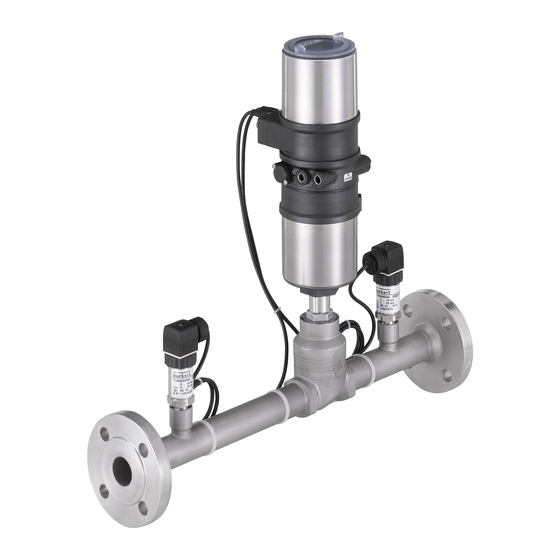
Flow controller
Hide thumbs
Also See for 8750:
- Quick start manual (64 pages) ,
- Short instructions for commissioning (82 pages)
Table of Contents
Advertisement
Quick Links
Advertisement
Table of Contents

Related Manuals for Burkert 8750


Summary of Contents for Burkert 8750
- Page 1 Type 8750 Flow controller Quickstart English...
- Page 2 We reserve the right to make technical changes without notice. Technische Änderungen vorbehalten. Sous réserve de modifications techniques. © Bürkert Werke GmbH & Co. KG, 201 - 2017 Operating Instructions 1705/0 _ / Original DE...
-
Page 3: Table Of Contents
Typ 8750 Typ 8750 TableofContents Display in AUTOMATIC operating state......17 1 QUICKSTART GUIDE .................5 Master code ................18 Definition of terms / Abbreviation .......... 5 9 ASSEMBLY ....................19 2 SYMBOLS ......................5 Safety instructions ..............19 3 AUTHORIZED USE ..................6 Before installation ..............19 Restrictions ................. - Page 4 Typ 8750 14.1 Settings in BUS.COMM............ 42 14.2 Configuration of the process data ........44 15 SAFETY END POSITIONS ..............48 16 ERROR MESSAGES ................. 49 16.1 Error messages on field bus devices ........51 16.2 Other error messages ............52 17 ACCESSORIES ................... 53 18 DISASSEMBLY .
-
Page 5: Quickstart Guide
1.1 Definition of terms / Abbreviation Important tips and recommendations. In these instructions, the term “device” always refers to the flow controller Type 8750. Refers to information in these operating instructions or in FMR = Flow controller other documentation. ▶ Indicates an instruction to prevent risks. -
Page 6: Authorized Use
Typ 8750 Authorizeduse AUTHORIZED USE BASIC SAFETY INSTRUCTIONS These safety instructions do not make allowance for any Non-authorized use of the flow controller Type 8750 may be a hazard to people, nearby equipment and the environment. • Contingencies and events which may arise during the installation, operation, and maintenance of the devices. ▶ The device is designed as a simple system for determining and controlling the volumetric flow rate of gases. - Page 7 Typ 8750 Basicsafetyinstructions NOTE! General hazardous situations. ▶ Devices without a separate Ex type label may not be used in a Electrostatic sensitive components/modules. potentially explosive area. The device contains electronic components which react sensitively ▶ Only trained technicians may perform installation and maintenance to electrostatic discharge (ESD).
-
Page 8: General Information
Warranty • The device is operated via 4 function keys and a display. The warranty is only valid if the flow controller Type 8750 is used as intended in accordance with the specified application conditions. The pressure drop is measured by the control valve as “measuring 5.3... -
Page 9: Structure
Typ 8750 Systemdescription 6.2 Structure 6.2.2 Influence of the process variables on the flow rate Process controller Type 8693 Pressure drop Flow rate of gases Actuator control Valve body control subcritical · ∆p valve Type 2301 valve Type 2301 = 514 · k > · p Signal line from Pressure sensor... - Page 10 Typ 8750 Systemdescription 6.2.3 Electrical interfaces Inputs for position (set-point value) 2 digital outputs or process set- point value Inputs for process 0...20 mA Process con- Analog actual value 4...20 mA troller Type Process con- position (4...20 mA) 0...5 V troller...
-
Page 11: Technical Data
Pressure sensor, gasket PTFE Seat seal EPDM 7.1 Conformity Control cone Stainless steel 1.4571 Type 8750 conforms to the EC directives according to the EC Dec- Spindle Stainless steel 1.4404 laration of Conformity. Dowel pin Stainless steel A2 7.2 Standards Inlet and outlet sections acc. to EN ISO 5167-1... -
Page 12: Type Label (Example)
Outlet sections already integrated in the system (6 x DN) Dimensions Orifice Main seal material ∅ 91 Control function Body material Type Pilot pressure 8750 A 50,0 PTFE VA Pilot 5,5- 7bar FLANSCH Pmed 16bar ∅ E Made in Germany 00123456 Flow 1 W12ME Order number Max. medium pressure... -
Page 13: Electrical Data
Typ 8750 Technicaldata 7.7 Electrical data Pressure range control medium 5,5...7 bar (DN15...DN50 port connection) Connections 5...6 bar Operating voltage circular plug-in connector M12 x 1, (DN65...DN100 port connection) 4-pole Intrinsic air consumption 0 l/min Internal system signals 2x circular plug-in connectors M8 x 1,... - Page 14 Typ 8750 Technicaldata Kv value table for FMR versions (specifications for valve stroke and flow rate in %) The measured set of values for each seat combination is stored in the FMR memory at the factory. Flow rate Kv in [%] Valve design Valve stroke POS [%]...
-
Page 15: Control And Display Elements
Typ 8750 Controlanddisplayelements 8.1 Function of the keys CONTROL AND DISPLAY ELEMENTS The functions of the 4 keys differ depending on the operating state (AUTOMATIC or MANUAL) and operating level (process level or setting level). Designation: The function of the keys is displayed in the gray text field which is Function of above the key. -
Page 16: Operating State
Typ 8750 Controlanddisplayelements 8.2 Operating state Function of the keys on the setting level: The process controller has 2 operating states: Function of the Description of the function AUTOMATIC and MANUAL keys Arrow key Scroll up in the menus AUTOMATIC In the AUTOMATIC operating state, normal Increase numerical values MENU controller mode is implemented. -
Page 17: Operating Levels
Typ 8750 Controlanddisplayelements 8.3 Operating levels 8.4 Display in AUTOMATIC operating state The process controller has 2 operating levels: • Process level set at the Description of the display Display Display and operation of the current process factory Operating state: AUTOMATIC / MANUAL • Setting level Set-point position of the valve actuator (0 –... -
Page 18: Master Code
Typ 8750 Controlanddisplayelements set at the set at the Description of the display Display Description of the display Display factory factory P.LIN Graphical display of SP and PV Automatic linearization of the – – with time axis process characteristics MENU SP / PV (t) HOLD MENU P.TUNE CMD/POS Simultaneous display of the nominal Graphical display of POS and –... -
Page 19: Assembly
Typ 8750 Assembly ASSEMBLY 9.2 Before installation The FMR can be installed in any position, preferably with the 9.1 Safety instructions process controller face up. DANGER! • For trouble-free flow characteristics on the pressure sensor, fit an inlet section upstream of the FMR (dimensions acc. - Page 20 Typ 8750 Assembly WARNING! Important information for the problem-free functioning of the device: Risk of injury when opening the actuator. • The installation must not cause back pressure to build up. The actuator contains a tensioned spring. If the actuator is • To make the connection, select a hose with sufficient cross opened, there is a risk of injury from the spring jumping out.
-
Page 21: Electrical Installation
Typ 8750 Electricalinstallation ELECTRICAL INSTALLATION Caution (exhaust air concept): In compliance with protection class IP67, an exhaust air line DANGER! must be installed in the dry area. Risk of electric shock. Keep the applied control pressure always 0.5...1 bar above ▶ Before reaching into the device, switch off the power supply and the pressure which is the minimum required to move the secure to prevent reactivation. -
Page 22: Electrical Installation, 24 V Dc With Circular Plug-In Connector (Multi-Pole Variant)
Typ 8750 Electricalinstallation 10.1 Electrical installation, 24 V DC with Circular plug M12, 8-pole circular plug-in connector (multi-pole Input signals from the variant) control center Output signals from the control center Signal values Circular plug M8, 4-pole Operating voltage 24 V DC Pressure sensor P1, P2 Set-point value 4...20 mA (0...20 mA; 0...5 V; 0...10 V) -
Page 23: Electrical Installation Profibus Dp
Typ 8750 Electricalinstallation 10.2 Electrical installation PROFIBUS DP Circular plug M12, 8-pole Set-point value, digital input Procedure: Wire color Assignment Set-point value + (0/4 – 20 mA / 0 – 5/10 V) → Connect the process controller according to “Fig. 13” and “Tab. blue Set-point value GND 10”, “Tab. - Page 24 Typ 8750 Electricalinstallation Circular plug M8, 4-pole (pressure sensor) Socket M12, 5-pole Wire color Assignment (inversely coded) (PROFIBUS DP) brown + 24 V pressure sensor power supply white 4 – 20 mA output from pressure sensor Tab. 11: Circular plug M8, 4-pole (pressure sensor)
-
Page 25: Electrical Installation Devicenet
Typ 8750 Electricalinstallation 10.3 Electrical installation DeviceNet Circular plug M12, 5-pole DeviceNet Procedure: → Connect the process controller according to “Fig. 14” and “Tab. 13”, “Tab. 14”, “Tab. 15”. Circular plug M8, 4-pole The electrical connection module of Type 8693 features a setscrew Pressure sensor P1, P2 with nut which is used to connect the Technical Earth (TE) (see “Fig. -
Page 26: Start-Up 24 V Dc
Typ 8750 Start-up24VDC START-UP 24 V DC Circular plug M12, 5-pole (bus connection) Signal WARNING! Shielding Risk of injury from improper operation. V– Improper operation may result in injuries as well as damage to the CAN H device and the area around it. CAN L ▶ Before start-up, ensure that the operating personnel are familiar Tab. -
Page 27: General Procedure For Creating Settings For The Flow Controller
Typ 8750 Start-up24VDC 11.1 General procedure for creating 11.2 Define basic settings settings for the flow controller Setting the input signal Action Description Procedure: Switching from MENU MENU Press for 3 s process level setting level (countdown in the Action Description display) Switching from MENU MENU Press for 3 s... -
Page 28: Automatic Adjustment (X.tune)
Typ 8750 Start-up24VDC 11.3 Automatic adjustment (X.TUNE) SELEC MENU ENTER MENU WARNING! 4-20 mA INPUT 0-20 mA Danger of injury due to the valve position changing when the X.TUNE function is run at operating pressure. 0-10 V ▶ Never run X.TUNE while the process is running. EXIT MENU 0- 5 V ▶ Secure system against unintentional activation. Fig. 15: Operating structure INPUT (select input signal) -
Page 29: Configuring The F.control Auxiliary Function
Typ 8750 Start-up24VDC Procedure: 11.4 Configuring the F.CONTROL auxiliary function Taste Action Description → Switching from MENU MENU Add the auxiliary function F.CONTROL to the main menu using Press for 3 s process level setting level the configuration menu (ADDFUNCTION). (countdown in the... - Page 30 Typ 8750 Start-up24VDC F.CONTROL - Settings: F.CONTROL PID.PARAM DBND 1 % ENTER ENTER Parameter settings for the PID process PID.PARAM 1,00 controller Insensitivity area (dead band) of the PID 999,9 DBND 0,1 % process controller 0,00 Amplification factor of the process controller 0,0 % FILTER EXIT Reset time Hold-back time F.PARAM...
- Page 31 Typ 8750 Start-up24VDC 11.4.1 Change the process set-point value Scaling the process controller PV-SCALE (m³/s or m³/h only) Procedure: Type of the set-point value default 1. Set the set-point value default on the setting level: SP-INPUT (internal or external) In the main menu (MAIN), select the F.CONTROL function...
-
Page 32: Leakage Air Characteristic For Fmr (Leaktune)
Typ 8750 Start-up24VDC 11.5 Leakage air characteristic for FMR NOTE! (LeakTune) If bulk material is conveyed pneumatically using a rotary The function LEAK.TUNE enables leakage air compensation which valve, ensure that increases the precision of the fluid flow rate control. ▶ the conveyor line behind the rotary valve is closed. Background: When bulk material is conveyed, leakage air occurs on ▶... -
Page 33: Additional Fmr Functions
Typ 8750 AdditionalFMRfunctions 11.5.2 Program sequence ADDITIONAL FMR FUNCTIONS • The control valve is closed. Overview • After 10 seconds settling time the primary pressure is recorded on ADD.FUNCTION CHARACT the fluid flow rate controller. ENTER CUTOFF The scaling of the x axis of the leakage air characteristic is DIR.CMD... - Page 34 Typ 8750 AdditionalFMRfunctions No Description No Description Selecting the transfer characteristic between input signal and Simulation of set-point value, process valve, process stroke (correction characteristic) Diagnosis menu (option) Sealing function for position controller Parameterization of the PID process controller Effective sense of direction between input signal and nominal Tab.
-
Page 35: Activating And Deactivating Auxiliary Functions
Typ 8750 AdditionalFMRfunctions 12.1 Activating and deactivating auxiliary You must exit the main menu by pressing the left selection functions before the modified data is saved to the EXIT MENU memory (EEPROM). During the save process, the save symbol You can activate the auxiliary functions on the setting level by adding is indicated on the display. - Page 36 Typ 8750 AdditionalFMRfunctions CAL.USER calibr. PV calibr. POS ENTER PV 4 mA 0 ENTER Create and confirm POS. pMIN ENTER INPUT minimum value INPUT PV 20mA 0 EXIT Create and Enter value confirm (POS.lower:) INPUT maximum value POS. pMAX EXIT CAL.FMR...
-
Page 37: Output - Configuration Of The Analog Output
Typ 8750 AdditionalFMRfunctions CAL.USER - Settings: calibr. PV Calibrating the process actual value calibr. POS Calibration of the position actual value for input signal 4 - 20 mA: POS. pMIN Set the minimum position of the valve PV 4mA 0 Minimum value of the input signal POS. pMAX Set the maximum position of the valve... -
Page 38: Profibus Dp Start-Up
Typ 8750 PROFIBUSDPstart-up PROFIBUS DP START-UP OUT ANALOG SELEC Procedure: Output of the actual value ENTER • Perform the automatic adjustment (X.TUNE) of the process controller. Output of the set-point value • Add the F.CONTROL auxiliary function to the main menu using the Output of the process actual value configuration menu (ADDFUNCTION) and make settings. -
Page 39: Configuration Of The Process Values
Temperature Bürkert homepage: Operation mode • “Configuration on the PROFIBUS by means of GSD file” Errors www.burkert.com → Type 8793 → Config. PROFIBUS by GSD file F.CONTRL active → EXIT First input the PDI (Process Data Input). Fig. 22: Operating structure BUS.COMM - 1... - Page 40 Typ 8750 PROFIBUSDPstart-up Name Description Identifier Name Description Identifier PDI:POS PDI:TEMP Actual position (position) GSD file: Device temperature (temperature) GSD file: PDI:POS PDI:TEMP Actual value of positioner as ‰. Temperature of 0.1 °C is Value range 0 – 1000. measured on the CPU board by...
- Page 41 Typ 8750 PROFIBUSDPstart-up PDO: Process Data Output (from the controller to the process Name Description Identifier controller) PDI:P1 Pressure before the valve GSD file: Name Description Identifier PDI:P1 0000-XXXX depending on sensor range Identifier (HEX): PDO: Process set-point value GSD file:...
-
Page 42: Devicenet Start-Up
Typ 8750 DeviceNetstart-up DEVICENET START-UP Name Description Identifier Procedure: PDO:ERR Reset error display GSD file: • Perform the automatic adjustment (X.TUNE) of the process controller. PDO: ERR If the value > 0, ERR is reset. • Add the F.CONTROL auxiliary function to the main menu using the Identifier (HEX): configuration menu (ADDFUNCTION) and create settings. - Page 43 Typ 8750 DeviceNetstart-up Activate or deactivate approach of the safety BUS FAIL BUS.COMM position Address X ENTER The actuator remains in the position which cor- SafePos off Input device responds to the set-point value last transferred Enter INPUT address. (default setting).
-
Page 44: Configuration Of The Process Data
Typ 8750 DeviceNetstart-up 14.2 Configuration of the process data 14.2.1 Static Input Assemblies The following components are required for the configuration: Name Address of data attribute Format of the data • Software suitable for the configuration. For example RSNetWorx for of the assemblies for attribute read access. DeviceNet (Rev. 4.12.00). Class, instance, attributes • ESD file (is on the supplied CD). - Page 45 Typ 8750 DeviceNetstart-up Name Address of data attribute Format of the data Name Address of data attribute Format of the data of the assemblies for attribute of the assemblies for attribute read access. read access. Class, instance, attributes Class, instance, attributes PV+P1+P2+ 4, 6, 3 Byte 0: PV low PV+POS+ 4, 8, 3 Byte 0: PV low MTMP+ERR Byte 1: PV high ERR+PCON Byte 1: PV high...
- Page 46 Typ 8750 DeviceNetstart-up Name Description of the input data Attribute Name Description of the input data Attribute attributes Address Class, attributes Address Class, Instance, Instance, Attribute; Data Attribute; Data type, Length type, Length Error 100, 1, 1; Actual position 111, 1, 59; Actual value of process controller INT, 2 byte Indicates the number of the process USINT, 1 byte as ‰.
- Page 47 Typ 8750 DeviceNetstart-up Nevertheless, by using this address data, the attributes combined 14.2.2 Static Output Assemblies in the assemblies can also be accessed acyclically at any time via Name Address of data Format of the data Explicit Messages. attribute of the assem- attribute blies for read access. Class, instance, Name Description of the output data Attribute attributes attributes...
-
Page 48: Safety End Positions
Typ 8750 Safetyendpositions SAFETY END POSITIONS Name Description of the output data Attribute attributes Address Class, Safety end positions after Instance, Actuator failure of the auxiliary power Designation Attribute; Data system type, Length electrical pneumatic Process set-point value 120, 1, 2; pilot-controlled Set-point value of process con- INT, 2 byte control system: single-acting troller in physical unit (as set in the down menu P.CO INP or P.CO SCAL),... -
Page 49: Error Messages
Typ 8750 Errormessages ERROR MESSAGES Error messages while the X.TUNE function is running General error messages (display only for external set-point value and Display Cause Remedial action with activated SIG.ERR). X.TUNE No compressed air Connect com- Display Cause Remedial action ERROR 1 connected. - Page 50 Typ 8750 Errormessages Error messages while the P.Q‘LIN / P.TUNE function is running Error messages while the LEAK.TUNE function is running Display Cause Remedial action Display Cause Remedial action P.Q LIN No compressed air connected. Connect compressed P1 error No primary pressure on the Switch on com- air.
-
Page 51: Error Messages On Field Bus Devices
Typ 8750 Errormessages 16.1 Error messages on field bus On DeviceNet devices Display Device state Remedial action Display Cause Remedial action BUS offline Offline. Device is not connected to the bus, the network access MFI fault Not possible, Field bus board Not possible, is displayed procedure (duplicate MAC-ID device defective. -
Page 52: Other Error Messages
Typ 8750 Errormessages 16.2 Other error messages BUS timeout I/O connection An I/O connection is in the TIME OUT state. is displayed timeout. Display Cause Remedial action → approx. every New connection estab- POS = 0 Sealing function Deactivate sealing 3 seconds lishment by master;... -
Page 53: Accessories
Typ 8750 Accessories ACCESSORIES DISASSEMBLY DANGER! Designation Order no. M12 connecting cable, 8-pole, Risk of injury from high pressure in the equipment/device. 919061 2 m assembled cable ▶ Before working on equipment or device, switch off the pressure M12 connecting cable, 4-pole, and deaerate/drain lines. 918038 5 m assembled cable Risk of electric shock. -
Page 54: Operating Structure
Typ 8750 Operatingstructure OPERATING STRUCTURE Process controller The factory presets are highlighted in blue to the right of the menu in the operating structure. Electrical connection Menu options activated or selected at the factory Menu options not activated or selected at the factory... - Page 55 Typ 8750 Operatingstructure M.TUNE.POS ACT.limit BUS PDI Position ACT.nolimit M.TUNE.PWM yB.min Process value yE.min Setpoint M.TUNE.AIR Temperature P.Q‘LIN Starting process Operation mode Errors P.TUNE Starting process F.CONTRL active Activatable ADD.FUNCTION CHARACT BUS PDO Setpoint auxiliary functions/ CUTOFF Operation mode main menu options Error reset EXTRAS F.CONTRL active...
- Page 56 Typ 8750 Operatingstructure GRAPH FREE Graph 0000 SECURITY Access Code CODE Y0 -> 0 % MAIN Y5 -> 5 % MANU/AUTO CUTOFF ADDFUNCT 100 % Y100 -> 100 % X.TUNE CUT-type Type PCO P.Q‘LIN Type XCO P.TUNE DIR.CMD Rise SAFEPOS...
- Page 57 Typ 8750 Operatingstructure FAILURE DIAG.State-1 OUTPUT OUT ANALOG OUT SPEZ FUNC.CHECK MAINTENANCE OUT.type normally open normally closed MTMP OUT BIN 2 POS.Dev Deviation 1.0 % 4 - 20 mA OUT.type Limit POS.Lim-1 0 - 20 mA 100 % Safepos 0 - 10 V ERR.SP/CMD...
- Page 58 Typ 8750 Operatingstructure CAL.USER calibr. POS POS.pMIN SER.I/O I/O.MODE HART POS.pMAX Burst INP 4mA calibr. SP Auto INP 20mA 9600 BAUDRATE calibr. FMR CAL.P-LIM Pmin SERIAL.CONFIG NONE par.,1 Stop Pmax EVEN par.,1 Stop P1 _ 4mA CAL.P1 ODD par.,1 Stop P1 _ 20mA NONE par.,2 Stop...
- Page 59 Typ 8750 Operatingstructure TEMP SIMULATION SIGNAL.sim Extern SIGNAL.form X.TUNE Sinus P.TUNE Square P.LIN Triangle MTMP Mixed P1| P2 50.0 % Offset 80.0 % Amplitude START-UP.ITEMS 5.0 sec Periode CONTROL.sim x.SIM p.SIM P1| P2 SIM.Gain SIM.Delay 2.0 sec DISP.MODE normal invers DIAGNOSE D.MSG...
- Page 60 Typ 8750 Operatingstructure TRAVEL.ACCU FAILURE PV.MONITOR FAILURE FUNC.CHECK FUNC.CHECK OUT.SPEZ OUT.SPEZ MAINTENANCE MAINTENANCE FAILURE CYCLE.COUNTER POS.MONITOR FAILURE FUNC.CHECK FUNC.CHECK OUT.SPEZ OUT.SPEZ MAINTENANCE MAINTENANCE TEMP.CHECK FAILURE ADD.DIAGNOSE HISTOGRAM FUNC.CHECK SERVICE.TIME OUT.SPEZ TAVEL.ACCU MAINTENANCE CYCLE.COUNTER TEMP.CHECK FAILURE STROKE.CHECK STROKE.CHECK FUNC.CHECK PV.MONITOR OUT.SPEZ POS.MONITOR...
- Page 61 Typ 8750 Operatingstructure 90d. 00h SERVICE.TIME LIMIT STROKE.CHECK NEXT M. HISTORY LIMIT ZERO.TOL 0.5 % 20.0 mm TRAVEL.ACCU MAX.TOL 1000 000 cm 0.5 % LIMIT HISTORY ZERO 1000 000 NEXT.M HISTORY 1000 000 LIMIT CYCLE.COUNTER 2.0 % PV.MONITOR DEADBAND 1000 000 NEXT.M...
- Page 62 Typ 8750 Operatingstructure 20 °C F.PARAM MTMP KV.FACT 1.293 Use KV.User DENSITY Use KV.FACT 80 mm SETUP DIAMETER Copy FACT–>USER MTMP.INPUT MANUELL LEAK-CHAR LeakChar inact 4-20 mA LeakChar active PV-SCALE PVmin LEAK.TUNE 0.0 m Character.P PVmax 100 m P1...P20 SP-INPUT intern Character.Q...
-
Page 63: Transport, Storage, Packaging
Typ 8750 Transport,Storage,Packaging TRANSPORT, STORAGE, PACKAGING NOTE! Transport damage. ▶ Inadequately protected devices may be damaged during transportation. ▶ Protect the device against moisture and dirt in shock-resistant packaging during transportation. ▶ Prevent the temperature from exceeding or dropping below the permitted storage temperature. - Page 64 Typ 8750 Transport,Storage,Packaging english...
- Page 66 www.burkert.com...
Need help?
Do you have a question about the 8750 and is the answer not in the manual?
Questions and answers