Table of Contents
Advertisement
Quick Links
Advertisement
Table of Contents

Related Manuals for Burkert 8745 MFM Ethernet


Summary of Contents for Burkert 8745 MFM Ethernet
- Page 1 Type 8745 Industrial Ethernet Analogue Mass Flow Meter (MFM) / Mass Flow Controller (MFC) Massendurchflussmesser (MFM) / Massendurchflussregler (MFC) Débitmètre massique (MFM) / Régulateur de débit massique (MFC) Operating Instructions Bedienungsanleitung Manuel d‘utilisation...
- Page 2 We reserve the right to make technical changes without notice. Technische Änderungen vorbehalten. Sous réserve de modifications techniques. © Bürkert SAS, 2017 - 2021 Operating Instructions 2103/01_EU-ML_00569558 / Original EN...
-
Page 3: Table Of Contents
Type 8745 Ethernet, 8745 Analogue Table of contents 5.4.2 Status LED for the fieldbus communi- The OperaTing insTrucTiOns ..........7 cation (product variant Ethernet) ......19 1.1 Definition of the term product ........7 Memory card ............19 1.2 Definition of the term Industrial Ethernet ....7 büS-interface ..............19 About NAMUR and the NAMUR Recommen- Control valve of an MFC........... 19 dation NE 107 ............. - Page 4 Type 8745 Ethernet, 8745 Analogue Pressure loss (MFM) ..........28 8.5.2 Relay output ........... 45 6.8.1 Operating gas is air ........28 8.6 Wire a product variant Analogue with 6 ter- minal connections ............ 46 6.8.2 Operating gas is not air ........30 Connecting the functional earth ....... 47 6.9 Electrical data ..............31 6.9.1 Product variant Ethernet ........31 cOmmissiOning ...............
- Page 5 Type 8745 Ethernet, 8745 Analogue 11 mainTenance ..............55 12.1.11 Product status indicator is yellow (MFC Analogue) ..........61 11.1 Maintenance for operation with heavily con- 12.1.12 Product status indicator is yellow taminated fluids ............55 (MFC Ethernet) ..........61 11.1.1 Inspect and clean the stainless steel 12.1.13 Product status indicator is blue ..... 62 mesh-filter ............
- Page 6 Type 8745 Ethernet, 8745 Analogue 13 accessOries, spare parTs ......... 65 13.1 Electrical accessories ..........65 13.2 Compression fittings for a product with G-in- ternal-threaded connections ........66 13.3 Mesh filters ............... 66 13.4 Additional documentation and software ....66 14 decOmmissiOning ............67 14.1 Safety instructions ............ 67 14.2 Dismantling the product ...........
-
Page 7: The Operating Instructions
Type 8745 Ethernet, 8745 Analogue The Operating instructions ThE OpErATing insTrucTiOns About NAMUR and the NAMUR Recommendation NE 107 The Operating Instructions describe the entire life cycle of the product. Please keep the Operating Instructions in a safe place, Standards committee for measurement and control technology accessible to all users and any new owners. (NAMUR) is an international association of users of automation systems for the process industry. -
Page 8: Intended Use
Type 8745 Ethernet, 8745 Analogue Intended use inTEndEd usE NOTICE Warns of damage to property. improper use of the product may be a hazard to people, nearby ▶ Failure to observe the warning may result in damage to the equipment and the environment. product or system. -
Page 9: Basic Safety Information
▶ Only use agents that are stable with the product materials for risk of injury from electric shocks. cleaning and decontamination ▶ Before working on the installation or product, switch off the Find the compatibility chart on our homepage: power supply. Make sure that nobody can switch the power country.burkert.com supply on. In the event of any ambiguity please contact your local sales office. ▶ Observe all applicable accident protection and all applicable safety regulations for electrical equipment. ▶ Do not make any modifications to the product and do not subject the product to mechanical stress. Burn hazard and fire hazard that are due to hot surface of the ▶... -
Page 10: General Information
Bürkert SAS • To minimise or even avoid any damage caused by an elec- Rue du Giessen trostatic discharge, take all the precautions described in the F-67220 TRIEMBACH-AU VAL EN 61340-5-1. • Do not touch any of the live electrical components. The addresses of our international sales offices are available on the internet at: country.burkert.com Warranty The warranty is conditional on compliant use of the product in observance of the operating conditions specified in the Oper- ating Instructions. Information on the Internet Operating Instructions and datasheets for the product can be found online at: country.burkert.com English... -
Page 11: Description
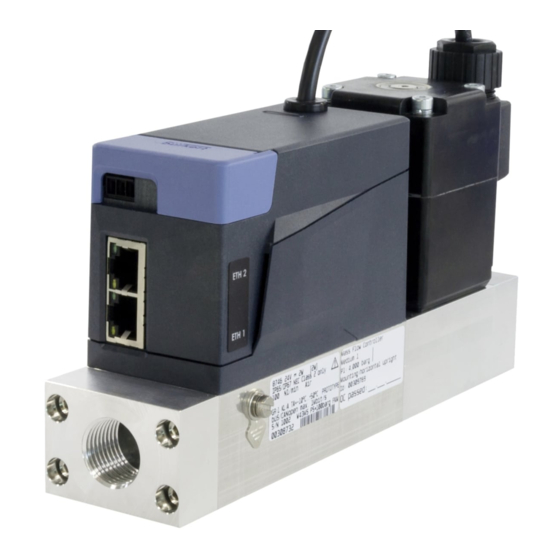
Type 8745 Ethernet, 8745 Analogue Description dEscripTiOn 1. Electrical connections: - 3 removable terminal connections that are delivered with Product variants the product - 2x RJ45 ports 5.1.1 mfm Ethernet 2. Status LEDs for the connection to the Ethernet network 3. Possible fluid connections: - G-internal-threaded connections according to DIN ISO 228/1 - NPT-internal-threaded connections according to ASME/ ANSI B 1.20.1 - flange connection 4. -
Page 12: Mfm Analogue
Type 8745 Ethernet, 8745 Analogue Description 5.1.2 mfm Analogue 2. Possible fluid connections: - G-internal-threaded connections according to DIN ISO 228/1 - NPT-internal-threaded connections according to ASME/ ANSI B 1.20.1 - flange connection 3. M4 screw for functional earth connection 4. Base block 5. Flow direction 6. Product status indicator. The indicator operates according to NAMUR NE 107. 7. büS interface for the Bürkert Communicator software 8. Slot for the memory card Fig. -
Page 13: Mfc Ethernet With Proportional Valve
Type 8745 Ethernet, 8745 Analogue Description 5.1.3 MFC Ethernet with proportional valve 3. Possible fluid connections: - G-internal-threaded connections according to DIN ISO 228/1 - NPT-internal-threaded connections according to ASME/ ANSI B 1.20.1 - flange connection 4. M4 screw for functional earth connection 5. Base block 6. Flow direction 7. Proportional valve 8. Product status indicator. The indicator operates according to NAMUR NE 107. -
Page 14: Mfc Analogue With Proportional Valve
Type 8745 Ethernet, 8745 Analogue Description 5.1.4 MFC Analogue with proportional valve 2. Possible fluid connections: - G-internal-threaded connections according to DIN ISO 228/1 - NPT-internal-threaded connections according to ASME/ ANSI B 1.20.1 - flange connection 3. M4 screw for functional earth connection 4. Base block 5. Flow direction 6. Proportional valve 7. Product status indicator. The indicator operates according to NAMUR NE 107. -
Page 15: Mfc Ethernet With Motor Valve
Type 8745 Ethernet, 8745 Analogue Description 5.1.5 MFC Ethernet with motor valve 1. Electrical connections: - 3 removable terminal connections that are delivered with the product - 2x RJ45 ports 2. Status LEDs for the connection to the Ethernet network 3. Status LED of the motor valve 4. Motor valve 5. Possible fluid connections: - G-internal-threaded connections according to DIN ISO 228/1 - NPT-internal-threaded connections according to ASME/ ANSI B 1.20.1... -
Page 16: Mfc Analogue With Motor Valve
Type 8745 Ethernet, 8745 Analogue Description 5.1.6 MFC Analogue with motor valve 4. Possible fluid connections: - G-internal-threaded connections according to DIN ISO 228/1 - NPT-internal-threaded connections according to ASME/ ANSI B 1.20.1 - flange connection 5. Base block 6. Product status indicator. The indicator operates according to NAMUR NE 107. 7. M4 screw for functional earth connection 8. Flow direction 9. - Page 17 Type 8745 Ethernet, 8745 Analogue Description Tab. 1. the highest priority. Refer to If the product status indicator flashes, then the product is selected in a man-machine interface such as the Bürkert Communi- cator software. Tab. 1: Product status indicator in accordance with NAMUR NE 107, edition 2006-06-12 , for active diagnostics colour colour code diagnostics event meaning according to (for a plc) according to NE 107 NE 107 Failure, error or fault MFM: Due to a malfunction of the product or its periphery, the measured values are not...
-
Page 18: Motor Valve Status Led
Type 8745 Ethernet, 8745 Analogue Description Motor valve status LED Status LEDs specific to a product variant Ethernet The colour and status of the motor valve status LED give the fol- lowing pieces of information: 5.4.1 Status LEDs for the connection to the • Whether the motor valve faces a problem or not. Ethernet network • Whether the motor valve is completely open or closed. Each RJ45 port of a product variant Ethernet variant has 2 LEDs to show the status of the connection to the network. Tab. 2: Status of the motor valve depending on the colour of the status Link/Act LED (green) Link LED (yellow) colour of... -
Page 19: Status Led For The Fieldbus Communication (Product Variant Ethernet)
Type 8745 Ethernet, 8745 Analogue Description 5.4.2 Status LED for the fieldbus loaded from country.burkert.com. communication (product variant • If the inserted memory card is empty, the product loads its Ethernet) own data on the memory card. A new memory card is empty. The data on the memory card can be transferred to another A product variant Ethernet has an LED to show the status of the product with the same article number. For example, the data can communication between the product and the PLC (Program- be transferred from a defective product to a new product. mable Logical Controller). -
Page 20: Technical Data
Type 8745 Ethernet, 8745 Analogue Technical data TEchnicAl dATA NOTICE if the valve seat seal is made of a hard material such as Conformity pcTfe, then the control valve may not be tight. The product complies with the EU directives according to the EU Products with a nominal valve diameter of 0.05 mm or 0.1 mm declaration of conformity (if applicable). have a valve seat seal made of a hard material. Standards The applied standards, which verify conformity with the EU direc- tives, can be found on the EU type examination certificate and/or... -
Page 21: Mfm Analogue
Type 8745 Ethernet, 8745 Analogue Technical data 6.3.1 mfm Analogue 6.3.2 mfm Ethernet Tab. 6: Operating conditions of an MFM Analogue Tab. 7: Operating conditions of an MFM Ethernet Ambient temperature –10 °C...+50 °C Ambient temperature –10 °C...+50 °C • –10 °C...+70 °C Fluid temperature The maximum temperature depends on the distance between 2 products. If the distance • –10 °C...+60 °C for oxygen between 2 products is smaller than 30 mm, Ambient humidity < 95%, non-condensing... -
Page 22: Mfc Analogue With Proportional Valve
Type 8745 Ethernet, 8745 Analogue Technical data 6.3.3 MFC Analogue with proportional valve 6.3.4 MFC Ethernet with proportional valve Tab. 8: Operating conditions of an MFC Analogue with proportional Tab. 9: Operating conditions of an MFC Ethernet with proportional valve valve •... -
Page 23: Mfc Analogue With Motor Valve
Type 8745 Ethernet, 8745 Analogue Technical data 6.3.5 MFC Analogue with motor valve 6.3.6 MFC Ethernet with motor valve Tab. 10: Operating conditions of an MFC Analogue with motor valve Tab. 11: Operating conditions of an MFC Ethernet with motor valve •... -
Page 24: Markings
Type 8745 Ethernet, 8745 Analogue Technical data Markings 6.4.2 Type label WARNING 874x 24V ... 11W [7,5W] Risk of injury caused by pressure, fluid escape. IP20 NEC Class 2 only Important product-specific data is indicated on the Type label 5,0 Nl/min Air 10,0 Nl/min Air and the calibration plate. Profinet 10/100Mbit/s ▶... -
Page 25: Conformity Marking, Certification Marking
16. IP-Code ETH 1 Fig. 9: Description of the Type label (example) Find the description of the older markings on the product Fig. 12: Marking with the Ethernet ports in the supplement at country.burkert.com Product materials 6.4.3 Conformity marking, certification marking Tab. 12: Product materials common to all product variants Analogue product part... -
Page 26: Dimensions, Weight
Type 8745 Ethernet, 8745 Analogue Technical data Fluid data Tab. 13: Product materials common to all product variants Ethernet product part material 6.7.1 Mass Flow Meter • Aluminium Base block • Stainless steel 1.4305 Tab. 16: Fluid data, MFM Housing Polycarbonate (PC) Calibration fluid Air or operating gas Seal Refer to the Type label... -
Page 27: Mass Flow Controller With Proportional Valve
Type 8745 Ethernet, 8745 Analogue Technical data 6.7.2 Mass Flow Controller with proportional 6.7.3 Mass Flow Controller with motor valve valve Tab. 18: Fluid data, MFC with motor valve Calibration fluid Air or operating gas Tab. 17: Fluid data, MFC with proportional valve Calibration fluid Air or operating gas Mass flow-rate range 20...2500 I... -
Page 28: Quality Of The Operating Fluid
Type 8745 Ethernet, 8745 Analogue Technical data Pressure loss (MFM) 6.7.4 Quality of the operating fluid Use the operating fluid that is given on the product Type-label. A Mass Flow Meter has a pressure loss that depends on the fol- The operating fluid must be clean and dry. lowing parameters: • the flow rate value The gas or gas mixture must obey the quality criteria in Tab. 19. The quality criteria are given in standard •... - Page 29 Type 8745 Ethernet, 8745 Analogue Technical data ∆p [mbar] ∆p [mbar] Example 0 100 1100 1300 1500 1000 1200 1400 Q [l /min] A: MFM with a base block for the 0...100 l /min flow rate range B: MFM with a base block for the 100...500 l /min flow rate range C: MFM with a base block for the 500...1500 l /min flow rate range 1500 1700 1900 2100 2300 2500 Q [l /min] 1600 1800 2000...
-
Page 30: Operating Gas Is Not Air
Type 8745 Ethernet, 8745 Analogue Technical data Example for argon gas that flows through an MFM with 1/2" 6.8.2 Operating gas is not air threaded fluid-connections: If the operating gas is not air, determine the pressure loss as 1. If the flow rate is 1400 l /min then the air pressure-loss p follows: as given in Fig. 13 is 140 mbar. 1. Read the air pressure-loss p from the diagrams in Fig. 13 2. The pressure loss for argon gas at a flow rate of 1400 l /min or in Fig. 14. is 164.4 mbar as given by the calculation in Fig. -
Page 31: Electrical Data
Type 8745 Ethernet, 8745 Analogue Technical data Electrical data 6.9.2 Product variant Analogue 6.9.1 Product variant Ethernet Tab. 22: Electrical data of an MFM with D-sub DE-9 male connector Operating voltage 24 V DC ±10 % WARNING (15 V DC ±10% on request) Maximum power consumption 2 W ▶ For UL-certified components, only use limited power circuits Digital input of "NEC Class 2". • 0...0,2 V •... - Page 32 Type 8745 Ethernet, 8745 Analogue Technical data Tab. 23: Electrical data of an MFM with 6 removable terminal Set-point analogue output connections • 0/4...20 mA • Maximum loop impedance: 600 W at Operating voltage 24 V DC ±10 % an operating voltage of 24 V DC (200 W (15 V DC ±10% on request) at an operating voltage of 15 V DC); Maximum power consumption 2 W Resolution: 20 µA Set-point analogue output • 0...5/10 V • Maximum current: 20 mA • 0/4...20 mA •...
-
Page 33: Communication Interface (Product Variant Ethernet)
Type 8745 Ethernet, 8745 Analogue Technical data • Identity (0x01) Set-point analogue output Predefined standard • 0/4...20 mA • Maximum loop impedance: 600 W at objects • Message Router (0x02) an operating voltage of 24 V DC (200 W • Assembly (0x04) at an operating voltage of 15 V DC); • Connection Manager (0x06) Resolution: 20 µA • DLR (0x47) • 0...5/10 V • Maximum current: 20 mA Resolution: 10 mV • QoS (0x48) • TCP/IP Interface (0xF5) 6.10 Communication interface (product •... -
Page 34: Fluid Installation
Type 8745 Ethernet, 8745 Analogue Fluid installation fluid insTAllATiOn Tab. 29: EtherCAT data Safety instructions • X1: EtherCAT IN Industrial Ethernet interface X1, X2 • X2: EtherCAT OUT DANGER Maximum number of cyclic 512 bytes in total risk of injury that is due to pressure in the installation or in input data and cyclic output the product. -
Page 35: Installation Steps
Type 8745 Ethernet, 8745 Analogue Fluid installation Product variant with G-internal- NOTICE threaded connections Risk of breakage of a product with motor valve. • Do not use the actuator housing of the motor valve as a lever WARNING arm. risk of injury that is due to leakage. Vibrations have an unwanted effect on the control valve ▶... - Page 36 Type 8745 Ethernet, 8745 Analogue Fluid installation Tab. 30: Stainless steel compression fittings and related seals product inter- article number No inlet section is required. nal-threaded pipe The connection to the pipe is explained for one side of the product. connection in stainless steel seal diameter The same procedure applies on the other side of the product. accordance with compression-fitting (1 piece) →...
- Page 37 Type 8745 Ethernet, 8745 Analogue Fluid installation → Observe the installation position that is given on the cali- → Insert the pipe in the compression-fitting body. Tighten the bration plate or in the calibration protocol. nut [a] by hand. See Fig. 20. → Slide the nut [a] and then the ferrule onto the pipe. See Fig. ferrule Fig. 20: Nut screwed by hand → Tighten the nut with an open-end spanner to a torque of 25...28 N·m, that is 18.44...20.65 lbf·ft. See Fig. 21. Fig. 18: Nut and ferrule on the pipe → Place the seal [C] on the product fluid-connection. → Screw the compression-fitting body [B] in the fluid con- nection. Tighten to a torque of 25...28 N·m, that is 18.44...20.65 lbf·ft. See Fig. 19. Fig.
-
Page 38: Product Variant With Npt-Internal-Threaded Connections
Type 8745 Ethernet, 8745 Analogue Fluid installation Product variant with NPT-internal- NOTICE threaded connections malfunction that is due to contamination. ▶ If a contaminated operating fluid is used, then install a WARNING filter upstream of the product. The filter mesh-size must be smaller than 25 µm. The filter ensures problem-free function- risk of injury that is due to leakage. ing of the product. See chpt. 6.7 Fluid data. ▶ At a low mass flow rate and a high pressure, make sure → Observe the installation position that is given on the cali- that the installation is tight. The tightness prevents incorrect measurements or the leakage of the operating fluid. -
Page 39: Product Variant With Flange Connections
Type 8745 Ethernet, 8745 Analogue Electrical installation ElEcTricAl insTAllATiOn Product variant with flange connections Safety instructions WARNING DANGER risk of injury that is due to leakage. risk of injury from electric shocks. At a low mass flow rate and a high pressure, make sure that ▶ Before working on the installation or the product, switch off the installation is tight. The tightness prevents incorrect meas- the power. Make sure that nobody can switch the power on. urements or the leakage of the operating fluid. ▶ Observe all applicable accident protection and all applicable safety regulations for electrical equipment. -
Page 40: Additional Documentation
Product variant Analogue FE (functional earth) • Product-specific help in the Bürkert Communicator software. DGND +24 V 8.2.2 Product variant Ethernet • Product-specific help in the Bürkert Communicator software. • Product description file and object description for the related product Type must be downloaded from country.burkert.com Fig. 23: Assignment of the connection terminals → To connect the functional earth, use a green-and-yellow cable that is as short as possible. And the cable cross-section must be at least equal to the cross section of the power supply cable. Alternatively to the connection to terminal 1, you can attach the functional-earth cable to the product M4-screw. Refer to chpt. 8.7. → Tighten the screws of the connection terminals to a torque of 0,22...0,25 N·m, that is 0,16...0,18 lbf·ft. -
Page 41: Change The Network Parameters
Type 8745 Ethernet, 8745 Analogue Electrical installation → Do the functional earthing of the product. Refer to chpt. 8.7. → Change the network parameters. To change the network parameters, you can use one of the following means: → Connect the product to the Industrial Ethernet network: - Bürkert Communicator software. Refer to chpt. 8.4. • If the EtherCAT protocol is used, then plug the incoming Eth- ernet cable (coming from the PLC) into the ETH1-port and plug - product web-server. You can only use the web server if the outgoing Ethernet cable into the ETH2-port. the protocols Modbus TCP or Ethernet/IP are active on the product. Refer to chpt 8.4. • If a protocol other than EtherCAT is used, plug an Ethernet cable in any or both ports. - the BOOTP protocol or the DHCP protocol, but only if the product uses the Ethernet/IP protocol. You must first acti- Both RJ45 ports have the same pin assignment. Refer to Fig. 24. vate the feature on the product with the Bürkert Communi- The cable shield is connected by the housing of the cator software. -
Page 42: Over The Product Web-Server
Type 8745 Ethernet, 8745 Analogue Electrical installation 8.4.1 Over the product web-server 4. Open the web browser. In the address bar of the web browser, enter 192.168.1.100. NOTICE The home page of the product web server opens. You can read security risk due to default passwords. some product data. Unauthorised persons can log in to the web server and change 5. To configure the network parameters of the product, open a the product parameters. web server session. ▶ Change default passwords. →... -
Page 43: Wire A Product Variant Analogue With D-Sub De-9 Male Connector
Type 8745 Ethernet, 8745 Analogue Electrical installation → Go to → If your product is an MFM, wire a D-sub DE-9 female con- industrial communication parameter nector according to the pin assignment in Fig. 25. → Change the parameters. d-sub de-9 male assignment → To update the parameters in the product, restart the product. connector The product restarts. Digital input The network parameters of the product are changed. GND for the digital input and the power supply Wire a product variant Analogue +24 V DC with D-sub DE-9 male connector Relay - Normally closed contact (Break contact) NOTICE... -
Page 44: Digital Input
Type 8745 Ethernet, 8745 Analogue Electrical installation 8.5.1 Digital input d-sub de-9 male assignment connector The D-sub DE-9 male connector has a digital input. A digital Digital input input is used to remotely trigger a function. The following func- GND for the digital input tions are some examples of the available functions: and the power supply • MFC: Start the function autotune, +24 V DC • MFC: Trigger the remote control of the actuator or trigger the Relay - Normally closed control of the actuator by the product. -
Page 45: Relay Output
Type 8745 Ethernet, 8745 Analogue Electrical installation Tab. 32: Actions triggered by the switching levels Action depending on the activated switching level Level 1 Level 2 Level 3 Activation: Activation: Activation: Short-circuit the digital input 1...4 V DC 5...28 V DC Function with the digital-input ground (alternatively: not connected) MFC: Triggers the function Not used Not used start autotune Triggers the closing of the Triggers the normal operating... -
Page 46: Wire A Product Variant Analogue With 6 Terminal Connections
Type 8745 Ethernet, 8745 Analogue Electrical installation → Loosen the screws of the removable terminal connections. Tab. 33: Default assignment of the relay output of the D-sub DE-9 male connector → If your product is an MFM, wire the removable terminal con- product variant analogue default assignment nections according to the pin assignment in Fig. 27 No assignment Terminal connections assignment The set-point value cannot be... -
Page 47: Connecting The Functional Earth
Location of the M4 screw for the connection of the functional- earth cable and the connection of the cable shielding 3. Vent the pipes completely. 3. Attach the functional-earth green-and-yellow cable to the M4 4. Energise the product. screw with a cable lug. If product-specific data is stored on the inserted memory 4. Tighten the M4 screw to a torque of 1,8 N·m...2 N·m, that is card, then the product adopts the data. To get a list of the stored 1,33 lbf·ft...1,47 lbf·ft. data at product delivery, refer to the Help for the Initiation file that can be downloaded from country.burkert.com. English... -
Page 48: Setting And Operation
Type 8745 Ethernet, 8745 Analogue Setting and Operation sETTing And OpErATiOn If the inserted memory card is empty, then the product loads its own data on the memory card. Possible problems related to 10.1 Safety instructions the memory card are given in chpt. 12.3.4 and chpt. 12.3.5. NOTICE DANGER If the memory card is defective or lost, then buy a new memory risk of injury that is due to pressure in the installation or in card from your Bürkert sales office. the product. 5. If the product is an MFC, and the operating fluid is not the ▶ Before working on the installation or product, cut the pres- calibration fluid or the pressure conditions have changed, sure. Vent and drain the pipes. -
Page 49: Functions
Type 8745 Ethernet, 8745 Analogue Setting and Operation 10.2.2 Flush mode (MFC Ethernet) WARNING NOTICE risk of injury that is due to improper operation. Improper operation can lead to injuries and damage to the If the control valve is fully open, then the internal product temper- product and its environment. ature increases. And if the internal product temperature increases, ▶ The operating personnel must have read and understood the then the product can be damaged. content of the Operating Instructions. • Do not let the control valve fully open for more than ▶ Observe the safety information and the intended use. 10 minutes. -
Page 50: 10.3.2 Product Variant Ethernet
→ To connect the product to the Bürkert Communicator software, do the following steps: software, refer to chpt. 10.4. → Buy the USB-büS-interface set with article number 00772551 → To get general information about the Bürkert Communi- from Bürkert. cator software, refer to the Operating Instructions for the → Download the latest version of the Type 8920 Bürkert Com- Type 8920. municator software from country.burkert.com • The network parameters of the product can be set with the → Install the Bürkert Communicator software on a PC. During product web server. The product web server can be used for installation, the büS stick must not be inserted at the PC. the following protocols: → Assemble the parts of the USB-büS-interface set. Refer to - EtherNet/IP Fig. 30. - Modbus TCP → To connect the product to the Bürkert web server and change the network parameters of the product, refer to chpt. 8.4. -
Page 51: User-Defined Adjustment
Type 8745 Ethernet, 8745 Analogue Setting and Operation 10.6 Operating modes of an MFC → Insert the micro-USB connector into the büS-interface for the Bürkert Communicator software. The location of the büS-in- When energizing the product for the first time, the product enters a terface on the product is given in chpt. 5.1. short initialisation phase and then switches to the normal operating → Wait until the Windows pilot of the büS stick has been com- mode. The normal operating mode is described in chpt. 10.7. pletely installed on the PC. The possible operating modes are described in Tab. 34. → Start the Bürkert Communicator software. Tab. 34: Names of the operating modes of an MFC in the Bürkert →... -
Page 52: Normal Operating Mode (Mfc)
Type 8745 Ethernet, 8745 Analogue Setting and Operation 10.7 Normal operating mode (MFC) The sensor measures the mass flow rate and compares the measured value x with the set-point value w. Then the product The normal operating mode is active when energizing the product calculates the set-point position value y of the control valve. The for the first time. Fig. 31. shows the normal operating mode of an set-point position value y determines the opening of the control MFC. valve. For example, if the set-point position value y is equal to 10%, then the opening of the control valve is 10%. NOTICE The transmission means of the set-point value w and the measured if the valve seat seal is made of a hard material such as value of the flow rate depends on the product. Refer to chpt. 10.7.1 pcTfe, then the control valve may not be tight. -
Page 53: Optimise The Closed-Loop Control Parameters (Mfc)
Type 8745 Ethernet, 8745 Analogue Setting and Operation analog set-point value operating mode. WARNING • The set-point value w is transmitted over the set-point ana- Risk of injury from flowing gas. logue input according to the ranges in Tab. 35. While the Autotune function is running, the gas flow can be • The measured value of the flow rate is transmitted over the higher than the nominal flow. analogue output according to the ranges in Tab. 35. ▶ Before running the Autotune function, make sure no danger Tab. 35: Analogue input ranges and analogue output ranges can occur if the gas flow increases. -
Page 54: Choose The Source Giving The Set-Point Value (Mfc)
On a product variant Ethernet you can alternatively change the with the graphical representation of process values to analyse related object. Refer to the related procedure in the product-spe- the system with the Bürkert Communicator software. cific help in the documentation of the initiation files. Download the 10.10 Set-point values without initiation files and the related documentation at country.burkert.com. communication (MFC Ethernet) The setting of the parameter set-point value source kept after a restart, except when the product performs the The function makes it possible to specify the set-point values of function analyze system. an MFC even if the communication with the external set-point value provider (for example a PLC) is broken. If the function is... -
Page 55: Maintenance
Type 8745 Ethernet, 8745 Analogue Maintenance mAinTEnAncE Download the initiation files and the related documentation at country.burkert.com. If no heavily contaminated fluids are used and if the product is operated according to the Operating Instructions, then the product is maintenance-free. 11.1 Maintenance for operation with heavily contaminated fluids DANGER risk of injury that is due to pressure in the installation or in the product. -
Page 56: Inspect And Clean The Stainless Steel Mesh-Filter
Type 8745 Ethernet, 8745 Analogue Maintenance 11.1.1 Inspect and clean the stainless steel WARNING mesh-filter Risk of injury that is due to improper maintenance work. The inspection and possibly cleaning of the stainless steel mesh- ▶ Only trained personnel can do the maintenance work. Per- filter must be done at regular intervals. The inspection frequency sonnel must use suitable tools. and cleaning frequency depend on the measured fluid. ▶ Secure the installation against unintentional actuation. ▶... -
Page 57: Cleaning And Recalibration At The Factory
Type 8745 Ethernet, 8745 Analogue Maintenance 11.2 Cleaning and recalibration at the groove on the rear side of the flange plate. factory → With a pair of tweezers, carefully remove the circlip [4] because the mesh filter [6] and the ring [5] will be pushed out If the product sensor is contaminated or damaged by operation, by the compression spring [7]. then the measured mass flow rate could no longer correspond to the actual mass flow rate. → Do not clean the mesh filter with tap water. → Send the product back to the manufacturer because the → Clean the stainless steel mesh-filter [6] with acetone, isopro- sensor must be replaced and recalibrated. Observe the return panol or compressed air. procedure given in chpt. 17 Returning the product. → Dry the mesh filter. 11.3 Replace the memory card → Before mounting the parts back, make sure that the To replace the memory card on the product, do the following: fine side of the mesh filter [6] faces the flange plate [2] →... -
Page 58: Troubleshooting
Type 8745 Ethernet, 8745 Analogue Troubleshooting TrOuBlEshOOTing → Push the new memory card in the slot until you hear a locking noise. If the memory card comes out, the locking failed. 12.1 Problems shown by the product status indicator The product status indicator changes its colour based on the NAMUR recommendation NE 107 to show diagnostics events. If several diagnostics events have been generated, then the product status indicator shows the diagnostics event with the Fig. 34: Inserted memory card highest priority. → Restart the product to write the product data on the new If the product is connected to a fieldbus, then the codes that are memory card. Possible problems related to the memory card related to the product states are transmitted on the fieldbus. Refer are given in chpt. 12.3.4 and chpt. 12.3.5. to chpt. 5.2. 12.1.1 Product status indicator is red (MFM Analogue) Identify the cause to solve the problem: 1. -
Page 59: Product Status Indicator Is Red (Mfm Ethernet)
Type 8745 Ethernet, 8745 Analogue Troubleshooting 12.1.2 Product status indicator is red (MFM 2. Incorrect Autotune or Autotune aborted. Ethernet) → Make sure that the fluid flows through the product. → Do the Autotune again. Identify the cause to solve the problem: 3. The sensor, the internal memory or the product is defective. 1. The supply voltage is out of the error range. The product can be damaged. → Contact the manufacturer, because maintenance is needed. → Operate the product within the specifications. If the product 12.1.4 Product status indicator is red (MFC status indicator is still red, then send the product back to Ethernet) Bürkert. -
Page 60: Product Status Indicator Is Orange (Mfm Analogue)
Type 8745 Ethernet, 8745 Analogue Troubleshooting 12.1.5 Product status indicator is orange 12.1.8 Product status indicator is orange (MFM Analogue) (MFC Ethernet) A calibration procedure is in progress. Identify the cause: → Wait until the calibration procedure is completed. 1. A calibration procedure is in progress. → Wait until the calibration procedure is completed. 12.1.6 Product status indicator is orange 2. The Autotune is in progress. (MFM Ethernet) →... -
Page 61: Product Status Indicator Is Yellow (Mfm Ethernet)
Type 8745 Ethernet, 8745 Analogue Troubleshooting 12.1.10 Product status indicator is yellow 2. The set-point position for the control valve has (almost) reached 100%. The set-point value cannot be reached. (MFM Ethernet) → Increase the inlet pressure or decrease the back pressure. Identify the cause: → If the pressure drop in the pipe is too high, reduce the 1. One of the following values is out of specification. The sensor pressure drop. or the product can be damaged. → If the filters that are installed in the pipe are dirty, clean the • the fluid temperature filters. • the product temperature 12.1.12 Product status indicator is yellow • the supply voltage (MFC Ethernet) →... -
Page 62: 12.1.13 Product Status Indicator Is Blue
Type 8745 Ethernet, 8745 Analogue Troubleshooting 12.2.2 LED is yellow and flashes 3. The Ethernet protocol is being changed. → Wait until the change of protocol is completed. This can take The ambient conditions or the process conditions for the motor up to 1 minute. valve are outside the authorized range. 12.1.13 Product status indicator is blue → Operate the product in the authorized range. There is an internal memory error. 12.3 Miscellaneous problems →... -
Page 63: Replacement Product Adopts None Of The Values From The Defective Product
Type 8745 Ethernet, 8745 Analogue Troubleshooting 2. The voltage drop in the connecting cable is too high. 12.3.6 No mass flow rate (MFM) → Increase the cross-section of the cable The pipes are too large or not yet fully vented. → Reduce the cable length. → Vent the pipes. 12.3.4 Replacement product adopts none of → Change the pipe diameter. the values from the defective product 12.3.7 No mass flow rate (MFC) Identify the cause to solve the problem: Identify the cause to solve the problem: 1. -
Page 64: Unstable Measured Value (Mfm)
Type 8745 Ethernet, 8745 Analogue Troubleshooting 12.3.8 Unstable measured value (MFM) 12.3.10 Set-point value at 0 %, but operating fluid still flows (MFC) You have not connected the functional earth (FE) properly. The operating pressure is above the tight sealing pressure of the → To connect the functional earth, use a green-and-yellow cable control valve. that is as short as possible. And the cable cross-section must be at least equal to the cross section of the power supply → Reduce the operating pressure. cable. Refer to chpt. 8.7. → To eliminate the defect, return the product to the manufacturer. 12.3.9 Unstable measured value (MFC) 12.3.11 Set-point value at 0 %, control valve is Identify the cause to solve the problem: closed, no mass flow, but a non-zero... -
Page 65: Set-Point Value Is Not Reached (Mfc)
Type 8745 Ethernet, 8745 Analogue Accessories, Spare Parts AccEssOriEs, spArE pArTs 12.3.12 Set-point value is not reached (MFC) Identify the cause to solve the problem: CAUTION 1. The mesh filter is clogged. risk of injury and risk of material damage that are due to → Clean or replace the mesh filter. unsuitable parts. → Run the Autotune function to adapt to the operating Incorrect accessories and unsuitable replacement parts can conditions. -
Page 66: Compression Fittings For A Product With G-Internal-Threaded Connections
901 540 G 1/4 1/4" 901 551 901 579 Tab. 40: Documentation and software G 1/4 3/8" 901 553 Product variant Ethernet: product Download from G 3/8 8 mm 901 542 901 576 description file and object description country.burkert.com G 3/8 10 mm 901 544 file G 3/8 1/4'' 901 555 901 580 Download from Bürkert Communicator software G 3/8 3/8'' 901 556 country.burkert.com G 1/2 10 mm 901 546 901 577 G 1/2... -
Page 67: Decommissioning
Type 8745 Ethernet, 8745 Analogue Decommissioning dEcOmmissiOning 14.2 Dismantling the product → Relieve the operating fluid pressure in the installation. 14.1 Safety instructions → Flush the product with a neutral fluid (for example nitrogen) → Relieve the flushing fluid pressure in the installation. DANGER → De-energise the product. risk of injury that is due to pressure in the installation and in → Remove the electrical wiring. the product. -
Page 68: Transport
Type 8745 Ethernet, 8745 Analogue Transport TrAnspOrT sTOrAgE, dispOsAl NOTICE NOTICE Transport damage. incorrect storage can cause damage to the product. • Close fluid connections with protective caps. If the product is not protected in transport, then the product can be damaged. • Store the product dry and dust-free in sealed zip-lock bags. • Remove cables, connectors, product-external filters and instalaltion • Storage temperature: –10...+70 °C. equipment. environmental damage that is due to parts contaminated by •... - Page 70 www.burkert.com...
Need help?
Do you have a question about the 8745 MFM Ethernet and is the answer not in the manual?
Questions and answers