Burkert 8793 Quick Start Manual
Electropneumatic positioner and process controller
Hide thumbs
Also See for 8793:
- Operating instructions manual (246 pages) ,
- Quick start manual (57 pages) ,
- Supplement to operating instructions (28 pages)

Related Manuals for Burkert 8793


Summary of Contents for Burkert 8793
- Page 1 Type 8792, 8793 Electropneumatic positioner and process controller Elektropneumatischer Positioner und Prozessregler Positionneur et régulateur de process électropneumatique Quickstart English Deutsch Français...
- Page 2 We reserve the right to make technical changes without notice. Technische Änderungen vorbehalten. Sous réserve de modifications techniques. © Bürkert Werke GmbH & Co. KG, 2009 - 2019 Operating Instructions 1902/09_EU-ML_00806106 / Original DE...
-
Page 3: Table Of Contents
14.2 Designation of the circular connectors and contacts ..29 Type label ..................10 14.3 Connection of the positioner Type 8792 ......30 Mechanical data...............11 14.4 Connecting the process controller Type 8793 ....31 Electrical data ................11 14.5 Electrical installation with cable gland ........33 Pneumatic data ................12 14.6 Terminal assignment for cable gland -... - Page 4 15.5 Electrical connection DeviceNet ..........41 16 START-UP ...................... 41 16.1 Safety instructions ..............41 16.2 Starting-up Type 8792 ............41 16.3 Start-up Type 8793 ...............43 17 ACCESSORIES ................... 45 17.1 Communications software.............45 18 PACKAGING, TRANSPORT, STORAGE .......... 46 19 DISPOSAL ..................... 46...
-
Page 5: Quickstart
Warns of a potentially dangerous situation! ▶ Failure to observe the warning may result in a serious or fatal injury. Quickstart for Type 8792/8793 explains, for example, how to install CAUTION! and start-up the device. A detailed description of the device can be found in the operating Warns of a possible danger! instructions for positioner Type 8792-8793. -
Page 6: Intended Use
▶ That the system cannot be activated unintentionally. operation. ▶ Installation and repair work may be carried out by authorised ▶ Use the Type 8792 and 8793 only as intended. technicians only and with the appropriate tools. english... -
Page 7: General Information
▶ Do not supply the supply pressure connection with any liquids. For the multi-pole version of the Type 8792/8793 we will ▶ Do not put any loads on the housing (e.g. by placing objects on provide you with cable connectors as accessories. -
Page 8: Warranty
Type 8792, 8793 DescriptionofSystem 5.3 Warranty DESCRIPTION OF SYSTEM The warranty is only valid if the Type 8792/8793 are used as intended 6.1 General description in accordance with the specified application conditions. The positioner Type 8792 / process controller Type 8793 is a digital, electro-pneumatic positioner for pneumatically actuated proportional 5.4... -
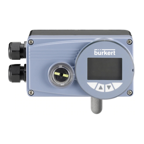
Page 9: Structure Of The Device
Connection options Type 8793 with external position sensor Shaft for position sensor Cable bushing * If the position sensor is connected to the process controller Type 8793 via the analog interface, it can be operated only Fig. 1: Structure Type 8792/8793 as a positioner (positioner). -
Page 10: Technical Data
7.1 Conformity connected correctly). In accordance with the Declaration of conformity, Type 8792 / 8793 * If the device is used under IP 67 conditions, the ventilation must be is compliant with the EU Directives. removed and the exhaust air conducted into the dry area (see “Fig. 1”) 7.2... -
Page 11: Mechanical Data
Type 8792, 8793 TechnicalData 7.6 Mechanical data Pt 100: Measuring range -20...+220 °C Resolution < 0,1 °C Dimensions See data sheet Measurement current < 1 mA Material Input data for set-point value signal Housing material Plastic-coated aluminium 0/4...20 mA: Input resistance 180 Ω... -
Page 12: Pneumatic Data
Symbol for the AUTOMATIC operating state Other symbols are displayed according to the activated functions. Oil content Quality class X, max. 25 mg/m³ See operating instructions Type 8792/8793 Temperature range of compressed air 0...+60 °C Abbreviated designation for... -
Page 13: Function Of The Keys
* The process values which can be displayed in the AUTOMATIC Change to MANUAL oper- MANU AUTOMATIC ating state operating state depend on type. A detailed description can be found in the operating instructions for Type 8792/8793. english... -
Page 14: Operating States
Type 8792, 8793 Operatingstates OPERATING STATES Key function on the setting level: Type 8792/8793 has 2 operating states: Key function Description of the function AUTOMATIC and MANUAL. Arrow key Scroll up in the menus AUTOMATIC Increase numerical values In the AUTOMATIC operating state normal Arrow key Scroll down in the menus controlled operation is implemented. -
Page 15: Displays In The Automatic Operating State
Type 8792, 8793 Operatingstates 9.2 Displays in the AUTOMATIC Type 8792 Description of the display Type 8793 operating state Graphical display of SP and PV Type 8792 Description of the display Type 8793 with time axis MENU SP / PV (t) HOLD Actual position of the valve actuator (0 – 100%) Graphical display of POS and... -
Page 16: Master Code
Type 8792 Description of the display Type 8793 There is the process level and the setting level for the operation and Automatic linearization of the P.LIN setting of Type 8792/8793. process characteristics Process level: MENU P.TUNE CMD/POS The running process is displayed and operated on this level. -
Page 17: Attachment And Assembly
Type 8792, 8793 Attachmentandassembly 11 ATTACHMENT AND ASSEMBLY Part no. Quantity Name U-bolt 11.1 Installation of devices for the hazardous area Hexagon bolt DIN 933 M8 x 20 When installing devices in the explosion-protected area, observe the Hexagon bolt DIN 933 M8 x 16 “Additional information for use in the hazardous area” enclosed with Circlip DIN 127 A8 the Ex-devices. - Page 18 Type 8792, 8793 Attachmentandassembly → 11.2.1 Installation Select short or long lever according to the stroke of the actuator. (see “Tab. 3: Attachment kit for linear actuators”). WARNING! → Assemble lever (if not pre-assembled) (see “Fig. 6”). Risk of injury from improper installation! Legend: ▶ Installation may be carried out by authorised technicians only and with the appropriate tools! No.
- Page 19 The scale printed on the lever is not relevant. 8792/8793 depends on the size of the actuator. → To determine the correct position, hold the Type 8792/8793 with Angular range of the lever Ideal: 60° mounting bracket on the actuator.
- Page 20 Legend: No. Name U-bolt Circlip Washer Legend: Hexagon nut No. Name Fig. 10: Attach Type 8792/8793 with mounting bracket; for actuators with Mounting bracket columnar yoke Hexagon bolt Circlip 10 11 11.2.3 Aligning lever mechanism Washer The lever mechanism cannot be correctly aligned until the Fig.
-
Page 21: Attachment To A Proportional Valve With Rotary Actuator
Determine home position and direction of rotation of the actuator. Setscrew DIN 913 M4 x 10 → Connect adapter to the shaft of the Type 8792/8793 and secure Hexagon bold DIN 933 M6 x 12 with 2 setscrews. Circlip B6... - Page 22 Fig. 11: Rotational range / anti-twist safeguard → → Assemble the multi-part assembly bridge* suitable for the Place Type 8792/8793 with assembly bridge on the rotary actuator. actuator and attach (see “Fig. 13”). → Attach the assembly bridge to the Type 8792/8793 using ③...
-
Page 23: External Position Sensor (Remote)
* If the position sensor is connected to the process controller of the Type 8792/8793 is not correctly aligned with the Type 8793 via the analog interface, it can be operated only shaft of the actuator. as a positioner (positioner). -
Page 24: Connection And Starting Up Of The External Position Sensor (Remote Operation)
Connect compressed air to Type 8792/8793. external position sensor (remote → Connect Type 8792/8793 pneumatically to the actuator. operation) → Switch on operating voltage to the Type 8792/8793. WARNING! → Run the X.TUNE function. Risk of injury from improper start-up! ▶ Start-up may be carried out by authorised technicians only and... - Page 25 When a 4 – 20 mA position sensor is connected, the process → Connect compressed air to the Type 8793. controller Type 8793 can be used as a positioner (positioner) → Connect Type 8793 pneumatically to the actuator only, as the process actual value input is used as input for the →...
-
Page 26: Pneumatic Connection
Type 8792, 8793 Pneumaticconnection 13 PNEUMATIC CONNECTION Procedure: → Apply supply pressure (1.4 – 7 bar) to the supply pressure con- DANGER! nection P. For single-acting actuators (control function A and B): Risk of injury from high pressure in the equipment! → ▶ Before loosening the pneumatic lines and valves, turn off the Connect one working connection (A1 or A2, depending on pressure and vent the pneumatic lines. -
Page 27: Safety End Positions
Type 8792, 8793 Pneumaticconnection 13.1 Safety end positions Single-acting actuators - control function A or B The safety end position following failure of the auxiliary electrical power depends on the pneumatic connection of the actuator to the working connections A1 or A2. 13.1.1 Single-acting actuators Safety end positions after failure of the Actuator system... -
Page 28: Electrical Installation
Type 8792, 8793 ElectricalInstallation 14 ELECTRICAL INSTALLATION 13.1.2 Double-acting actuators The descriptions for the electrical connection of the Safety end positions after failure of the PPOFIBUS-DP and DeviceNet designs can be found in Actuator system electrical pneumatic chapter “15 PROFIBUS DP / DeviceNet” auxiliary power auxiliary power → Connection upper according to “Fig. -
Page 29: Designation Of The Circular Connectors And Contacts
Type 8792, 8793 ElectricalInstallation 14.2 Designation of the circular Location of the switch: connectors and contacts Location of the switch Binary outputs Operating voltage Process actual and diverse signals value X4 - M8, 4-pole X1 - M12, 8-pole X5 - M8, 4-pole socket circular connector circular connecto Symbols for switch position Switch on... -
Page 30: Connection Of The Positioner Type 8792
Type 8792, 8793 ElectricalInstallation 14.3 Connection of the positioner Type On the External circuit/ Signal Pin Configuration 8792 device side level → Output signals to the control centre (e.g. PLC) - (only used for Connect pins according to the model (options) of the positioner. analog output option) 14.3.1 X1 - M12, 8-pole circular connector (red)* + (0/4...20 mA or 0...5/10 V) On the External circuit/ Signal completely galvanically Analogue Pin Configuration... -
Page 31: Connecting The Process Controller Type 8793
Type 8792, 8793 ElectricalInstallation 14.3.2 X4 - M8, 4-pole socket (for binary 14.4 Connecting the process controller outputs option only) Type 8793 Output signals to the control centre → First connect the process controller as described in chapter “14.3 (e.g. PLC) Connection of the positioner Type 8792”. On the External circuit / 14.4.1 X5 - M8, 4-pole circular connector, Pin Configuration device side Signal level process actual value input Binary output 1 0...24 V... - Page 32 Now make the required basic settings and actuate the automatic (blue)* Clock input – Clock – / adjustment of the process controller. The procedure is described (GND) GND (iden- Switch in chapter“16.3 Start-up Type 8793”. tical with on left GND oper- ating voltage) (black)* not used Frequency...
-
Page 33: Electrical Installation With Cable Gland
Using the 4 – 20 mA set-point value input → Unscrew the 4 screws on the housing cover and remove the If several devices of Type 8792/8793 are connected in series cover. and the power supply to a device in this series connection The screw-type terminals are now accessible. -
Page 34: Terminal Assignment For Cable Gland - Positioner Type 8792
Type 8792, 8793 ElectricalInstallation 14.6 Terminal assignment for cable 14.6.2 Output signals to the control centre (e.g. PLC) gland - positioner Type 8792 (required for analogue output and/or 14.6.1 Input signals from the control centre binary output option only) (e.g. PLC) → Connect terminals according to the model (options) of the positioner. External circuit / Signal On the device Terminal Configuration side level On the device Terminal Configuration External circuit / Signal level side 11 + Set-point 11 + + (0/4...20 mA or 0...5/10 V) -
Page 35: Terminal Assignment For Cable Gland - Process Controller Type 8793
Type 8792, 8793 ElectricalInstallation Connection of a potentiometric position sensor: 14.6.4 Terminal assignment for external position sensor (for remote model only) On the Terminal Configuration device External circuit Connection of the digital, contact-free position sensor side Type 8798: Potentiometer 1 1 On the Terminal Configuration External circuit / Signal level device side Potentio- Wiper 2 Wiper meter Supply sensor Remote Potentiometer 3 3 Sensor Supply sensor Type S –... - Page 36 Clock input – → Now make the required basic settings and actuate the automatic adjustment of the process controller. The procedure is described GND from operating Clock voltage – (GND) in chapter “16.3 Start-up Type 8793”. english...
-
Page 37: Profibus Dp / Devicenet
FE (inversely coded for PROFIBUS) Functional earth FE * (inversely coded for PROFIBUS) Fig. 22: PROFIBUS DP / DeviceNet; Fig. 23: PROFIBUS DP / DeviceNet; circular connectors and contacts - Type 8792 circular connectors and contacts - Type 8793 english... -
Page 38: Electrical Installation Profibus / Devicenet
Type 8792, 8793 PROFIBUSDP/DeviceNet 15.3 Electrical Installation 15.3.1 X1 - M12, 8-pole circular connector PROFIBUS / DeviceNet On the External circuit / Signal Pin Configuration device side level DANGER! not used Risk of injury due to electrical shock! not used ▶ Before reaching into the device or the equipment, switch off the operating voltage and secure to prevent reactivation! Operating voltage ▶ Observe applicable accident prevention and safety regulations 24 V DC ±... - Page 39 Tab. 19: Plug assignments; PROFIBUS DP / DeviceNet; supplied (white)* Clock input Clock + X5 -M8, 4-pole circular connetor - process actual value input (Type 8793) (blue)* Clock input – Clock – / (GND) GND (iden- Switch Connect the Pt 100 sensor via 3 cables for cable compen-...
-
Page 40: Electrical Connection Profibus
Tab. 22: Pin assignment PROFIBUS DP; X2/X3 - M12, 5-pole circular connector/socket - bus connection, On the device PROFIBUS DP Pin Configuration External circuit side When the operating voltage is applied, Type 8792/8793 is activated. Potentiometer 1 → Potentio- Now make the required basic settings: Wiper 2 meter... -
Page 41: Electrical Connection Devicenet
To change from the process to the setting level, press the key for approx. 3 seconds. MENU When the operating voltage is applied, Type 8792/8793 is activated. You must make the following basic settings for starting up: →... - Page 42 0-20 mA • Determination of parameters of the PWM signals to control the 0-10 V solenoid valves integrated in Type 8792/8793. • Setting of the controller parameters of the positioner. Optimization 0-5 V EXIT occurs according to the criteria of the shortest possible transient time with simultaneous freedom from overshoot.
-
Page 43: Start-Up Type 8793
Type 8792, 8793 Start-Up 16.3 Start-up Type 8793 To stop X.TUNE, press the left or right selection key STOP To be able to operate the positioner as a process controller, perform the following steps: Procedure: 1. S etting up the positioner: Action Description Description see “16.2.1 Specifying the standard settings”... - Page 44 Type 8792, 8793 Start-Up 16.3.1 Basic settings of the process P.CONTROL - settings: controller PID.PARAMETER Parameter settings of the process controller → In the main menu (MAIN) select the P.CONTROL function and DBND 0,1 % Insensitivity area of the PID process controller make the basic settings. 0,00 Amplification factor of the process controller...
-
Page 45: Accessories
Type 8792, 8793 Accessories 16.3.2 Manually changing the process set- 17 ACCESSORIES point value Designation Order no. Vorgehensweise: USB Interface for serial communication 227 093 1. S et the internal preselected set-point value on the setting level: Information at In the main menu (MAIN) select the P.CONTROL function Communicator www.burkert.com... -
Page 46: Packaging, Transport, Storage
Type 8792, 8793 Packaging,Transport,Storage 18 PACKAGING, TRANSPORT, STORAGE NOTE! Transport damages! Inadequately protected equipment may be damaged during transport. • During transportation protect the device against wet and dirt in shock-resistant packaging. • Avoid exceeding or dropping below the allowable storage temperature. Incorrect storage may damage the device. • Store the device in a dry and dust-free location! •... - Page 48 www.burkert.com...
Need help?
Do you have a question about the 8793 and is the answer not in the manual?
Questions and answers