Siemens SINUMERIK 808D ADVANCED Programming And Operating Manual
Computer numeric control
Hide thumbs
Also See for SINUMERIK 808D ADVANCED:
- Diagnostic manual (566 pages) ,
- Parameter manual (524 pages) ,
- Commissioning manual (508 pages)
Table of Contents
Advertisement
SINUMERIK
SINUMERIK 808D ADVANCED
Programming and Operating Manual (Turning)
User Manual
Legal information
Warning notice system
This manual contains notices you have to observe in order to ensure your personal safety, as well as to prevent damage to property. The
notices referring to your personal safety are highlighted in the manual by a safety alert symbol, notices referring only to property damage
have no safety alert symbol. These notices shown below are graded according to the degree of danger.
DANGER
indicates that death or severe personal injury will result if proper precautions are not taken.
WARNING
indicates that death or severe personal injury may result if proper precautions are not taken.
CAUTION
indicates that minor personal injury can result if proper precautions are not taken.
NOTICE
indicates that property damage can result if proper precautions are not taken.
If more than one degree of danger is present, the warning notice representing the highest degree of danger will be used. A notice warning of
injury to persons with a safety alert symbol may also include a warning relating to property damage.
Qualified Personnel
The product/system described in this documentation may be operated only by personnel qualified for the specific task in accordance with
the relevant documentation, in particular its warning notices and safety instructions. Qualified personnel are those who, based on their
training and experience, are capable of identifying risks and avoiding potential hazards when working with these products/systems.
Proper use of Siemens products
Note the following:
WARNING
Siemens products may only be used for the applications described in the catalog and in the relevant technical documentation. If products
and components from other manufacturers are used, these must be recommended or approved by Siemens. Proper transport, storage,
installation, assembly, commissioning, operation and maintenance are required to ensure that the products operate safely and without any
problems. The permissible ambient conditions must be complied with. The information in the relevant documentation must be observed.
© Siemens AG 2015. All rights reserved
6FC5398-5DP10-0BA2, 06/2015
1
Advertisement
Table of Contents

Related Manuals for Siemens SINUMERIK 808D ADVANCED


Summary of Contents for Siemens SINUMERIK 808D ADVANCED
- Page 1 WARNING Siemens products may only be used for the applications described in the catalog and in the relevant technical documentation. If products and components from other manufacturers are used, these must be recommended or approved by Siemens. Proper transport, storage, installation, assembly, commissioning, operation and maintenance are required to ensure that the products operate safely and without any problems.
-
Page 2: Preface
My Documentation Manager (MDM) Under the following link you will find information to individually compile your documentation based on the Siemens content: www.siemens.com/mdm Standard scope This manual only describes the functionality of the standard version. Extensions or changes made by the machine tool manufacturer are documented by the machine tool manufacturer. -
Page 3: Table Of Contents
Table of contents Preface ................................... 2 Fundamental safety instructions ..........................7 General safety instructions ........................7 Industrial security ............................ 7 Introduction................................8 CNC operator panels ..........................8 2.1.1 Panel Processing Unit (PPU) versions ....................8 2.1.2 Control elements on the PPU161.3 ......................8 Machine control panels .......................... - Page 4 External data backup ..........................50 7.2.1 External data backup in a data archive ....................50 7.2.2 Exernal data backup of separate files ....................52 Programming principles ............................53 Fundamentals of programming ......................53 8.1.1 Program names ............................ 53 8.1.2 Program structure ..........................53 Positional data ............................
- Page 5 8.12 Miscellaneous function M ........................106 8.13 H function ............................107 8.14 Arithmetic parameters, LUD and PLC variables .................. 107 8.14.1 Arithmetic parameter R ........................107 8.14.2 Local User Data (LUD) ........................108 8.14.3 Reading and writing PLC variables ..................... 109 8.15 Program jumps ............................
- Page 6 Other settings in "JOG" mode ......................202 A.6.1 Setting the relative coordinate system (REL) ..................204 A.6.2 Setting the JOG data ........................... 204 Activating the contour handwheel via the NC program ............... 205 Notes on part programs in "MDA" mode ..................... 207 The help system ..........................
-
Page 7: Fundamental Safety Instructions
With this in mind, Siemens’ products and solutions undergo continuous development. Siemens recommends strongly that you regularly check for product updates. For the secure operation of Siemens products and solutions, it is necessary to take suitable preventive action (e.g. cell protection concept) and integrate each component into a holistic, state-of-the-art industrial security concept. Third-party products that may be in use should also be considered. -
Page 8: Introduction
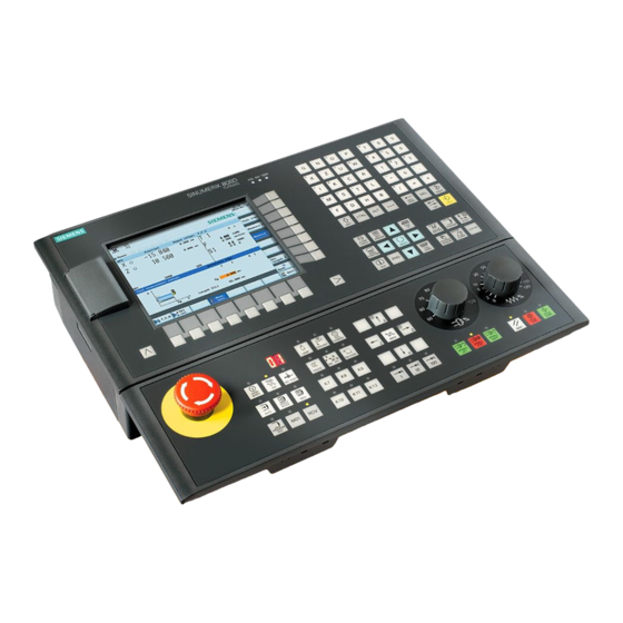
Panel Processing Unit (PPU) versions PPU version Panel layout Applicable control system PPU161.3 Horizontal, English version SINUMERIK 808D ADVANCED T (Turning)/M (Milling) Horizontal, Chinese version 2.1.2 Control elements on the PPU161.3 ① Vertical and horizontal softkeys Calls specific menu functions ②... - Page 9 To open the system data management operating area, press the following key combination: Enables user-defined extension applications, for example, generation of user dialogs with the EasyXLanguage function. For more information about this function, see the SINUMERIK 808D/SINUMERIK 808D ADVANCED Function Manual. USB interface...
-
Page 10: Machine Control Panels
Machine control panels 2.2.1 Machine Control Panel (MCP) versions MCP version Applicable control system Horizontal MCP, English version SINUMERIK 808D ADVANCED T (Turning)/M • (Milling) Horizontal MCP, Chinese version • Vertical MCP with a reserved slot for the handwheel, English version •... - Page 11 User-defined keys Pressing this in any operating mode switches on/off the lamp. LED on: The lamp is switched on. LED off: The lamp is switched off. Pressing this key in any operating mode switches on/off the coolant supply. LED on: The coolant supply is switched on. LED off: The coolant supply is switched off.
-
Page 12: Screen Layout
4. Pull out the pre-inserted strips from the MCP. 5. Insert the customized strips on the back of the MCP. Note This manual assumes a SINUMERIK 808D ADVANCED standard MCP. Should you use a different MCP, the operation may be other than described herein. Screen layout... -
Page 13: Protection Levels
The control system delivered by Siemens is set by default to the lowest protection level 7 (without password). If the password is no longer known, the control system must be reinitialized with the default machine/drive data. All passwords are then reset to default passwords for this software release. -
Page 14: Setting User Interface Language
Protection level 7 Protection level 7 is set automatically if no password is set and no protection level interface signal is set. The protection level 7 can be set from the PLC user program by setting the bits in the user interface. In the menus listed below the input and modification of data depends on the set protection level: ●... -
Page 15: Turning On, Reference Point Approach
Turning on, reference point approach Note When turning on the CNC and the machine, also observe the machine tool manufacturer's documentation, since turning-on and reference point approach are machine-dependent functions. Operating sequence Switch on the power supply for the control system and the machine. Release all emergency stop buttons on the machine. -
Page 16: Setting-Up
Setting-up Coordinate systems As a rule, a coordinate system is formed from three mutually perpendicular coordinate axes. The positive directions of the coordinate axes are defined using the so-called "3-finger rule" of the right hand. The coordinate system is related to the workpiece and programming takes place independently of whether the tool or the workpiece is being traversed. - Page 17 The figure below shows an example of the machine coordinate system of a turning machine. The origin of this coordinate system is the machine zero. This point is only a reference point which is defined by the machine manufacturer. It does not have to be approachable. The traversing range of the machine axes can be in the negative range.
-
Page 18: Setting Up Tools
The figure below shows an example of the workpiece clamped on the machine. Current workpiece coordinate system The programmed work offset TRANS (Page 56) can be used to generate an offset with reference to the workpiece coordinate system, resulting in the current workpiece coordinate system. Setting up tools 4.2.1 Creating a new tool... - Page 19 Enter the tool number (value range: 1 to 31999; preferentially enter a value less than 100) and select the corresponding tool edge position code according to the actual tool point di- rection in the following windows: Available edge positions for turning tool and grooving tool: 1, 2, 3 and 4 (taking new •...
-
Page 20: Activating The Tool
Note: ④ Column is invisible in Siemens mode. The function of activating the compensation • data via the "H" column is active only in ISO dialect mode. ⑦ Column is visible only when you set bit 18 of MD19730 to 1, that is, MD19730 = •... -
Page 21: Assigning The Handwheel
4.2.3 Assigning the handwheel Method 1: Assigning through the PPU Select the desired operating area. Open the machine data window. Press this softkey to open the basic machine data list. Use the cursor keys or the following softkey to search for the general machine data "14512 USER_DATA_HEX[16]". -
Page 22: Activating The Spindle
The axis identifier (for example, "X") which appears in the window indicates that you have assigned the handwheel to the selected axis. Select the required override increment with the following axis traversing keys on the MCP to move the selected axis. The override increment is 0.001 mm. -
Page 23: Measuring The Tool (Manually)
Press this key to select the spindle direction. Use this key or move the cursor to confirm your entries. Press this key on the MCP to activate the spindle. 4.2.5 Measuring the tool (manually) Overview The geometries of the machining tool must be taken into consideration when you execute a part program. These are stored as tool offset data in the tool list. - Page 24 See the following illustration for determining the length offsets using the example of a drill: Length 1/Z axis See the following illustration for determining the length offsets using the example of a milling tool: Operating sequence Measuring the tool in the X direction Select the desired operating area.
- Page 25 Move the tool to approach the workpiece in the X direction. Switch to handwheel control mode. Select a suitable override feedrate, and then use the handwheel to move the tool to scratch the required workpiece edge (or the edge of the setting block, if it is used). Enter the workpiece diameter in the "Ø"...
- Page 26 Measuring the tool in the Z direction Select the desired operating area. Switch to "JOG" mode. Open the manual tool measurement window. Press this vertical softkey to measure the tool in the Z direction. Move the tool to approach the workpiece in the Z direction. Switch to handwheel control mode.
-
Page 27: Verifying The Tool Offset Result In "Mda" Mode
Note: For a milling tool with edge position 6 or 8, the radius of the tool itself is displayed in the following window: Save the length value in the Z axis. Press this softkey and you can see that the compensation data values have been automati- cally added to the tool data. -
Page 28: Entering/Modifying The Tool Wear Data
To display additional G functions, use the corresponding keys. This window displays the auxiliary and M functions currently active. To close the window, press this softkey once again. This softkey opens the file saving window where you can specify a name and a storage medium for the program displayed in the MDA window. -
Page 29: Operating Area Overview
Press this key or move the cursor to activate the compensation. Operating area overview When working with the CNC, you need to set up the machine and the tools, etc. as follows: ● Create the tools and cutting edges. ● Enter/modify the tool and work offsets. ●... -
Page 30: Part Programming
Part programming The control system can store a maximum of 300 part programs which include those created by the control system for certain functions such as MM+, TSM, and so on. Softkey functions Pressing this key on the PPU allows you to open the following window: ①... -
Page 31: Creating A Part Program
Creating a part program Operating sequence Select the desired operating area. Enter the folder for the new program to be created. If you desire to directly create a new program file, press this softkey and proceed directly to Step 4. If you desire to create a new program directory first, press this softkey and proceed as fol- lows before you go to Step 4: A. - Page 32 Select the program file you desire to edit. You can also search for a file or directory by ei- ther: Pressing this softkey and specifying the desired criteria in the search dialog. Note that • the file extension ".MPF" or ".SPF" must be entered if you desire to search for a program file.
-
Page 33: Managing Part Programs
Copying, cutting, and pasting blocks Proceed through the following steps to copy, cut, and paste blocks: Press this softkey in the opened program editor window to insert a marker. Use the cursor keys to select the desired program blocks. Press the corresponding softkey/key to copy/cut the selection to the buffer memory. Place the cursor on the desired insertion point in the program and press this softkey. - Page 34 Press this softkey to start the search. Pressing this softkey cancels the search. Copying, cutting, and pasting programs Select the desired operating area. Open the desired directory. Select the program file that you would like to copy. Perform either of the following operations as desired: Press this softkey to copy the selected file or directory: •...
- Page 35 If you want to restore the last deleted file, press this softkey. Renaming programs Select the desired operating area. Open the desired directory. Select the program file that you would like to rename. Press the extension softkey to access more options. Press this vertical softkey to open the window for renaming.
-
Page 36: Automatic Machining
Automatic machining Overview The machine must have been set up for "AUTO" mode according to the specifications of the machine manufacturer. You can perform such operations as program start, stop, control, block search, and real-time simulation, etc. Softkey functions Switch to "AUTO" mode by pressing these keys. →... -
Page 37: Simulating Machining
Parameters ① Displays the axes that exist in the machine coordinate system (MCS), workpiece coordinate system (WCS), or relative coordinate system (REL). ② Displays the current position of the axes in the selected coordinate system. ③ Displays the remaining distance for the axes to traverse. ④... - Page 38 Switch to "AUTO" mode. Press this softkey to open the program simulation window, and the program control mode PRT is automatically activated. If the control system is not in the correct operating mode, a message will appear at the bottom of the screen as follows. If this message appears, repeat Step 4. Press this key to start the standard simulation for the execution of the selected part pro- gram.
-
Page 39: Simultaneous Recording Prior To Machining Of The Workpiece
6.1.2 Simultaneous recording prior to machining of the workpiece Before machining the workpiece on the machine, you can graphically display the execution of the program on the screen to monitor the result of the programming. Operating sequence Select the desired operating area. Select a part program for simulation. -
Page 40: Program Control
Press this key to start the recording. The machining of the workpiece is started and graph- ically displayed on the screen. Program control Operating sequence Select the desired operating area. Switch to "AUTO" mode. Press this softkey to open the lower-level menu for program control. Press the corresponding vertical softkey to activate or deactivate the desired program con- trol option (see table below for detailed softkey functions). -
Page 41: Program Test
Each block is decoded separately, and a stop is performed at each block. However, for the thread blocks without dry run feedrate, a stop is only performed at the end of the current thread block. It functions the same as pressing the following key: After activating this option, the icon "SBL"... - Page 42 Turn the feedrate override switch slowly to the desired value. Press this key to stop the program test. Testing the program with PRT In PRT mode, you can simply check the correctness of your part program with no axis or spindle movement. Proceed as follows to test a part program in PRT mode.
-
Page 43: Starting And Stopping/Interrupting A Part Program
Press this vertical softkey to activate the AFL function. Press this key on the MCP to close the door in the machine (if you do not use this function, just close the door in the machine manually). Make sure the feedrate override is 0%. Press this key on the MCP to run the program. -
Page 44: Executing/Transferring A Part Program Through The Ethernet Connection
Executing/transferring a part program through the Ethernet connection 6.5.1 Configuring the network drive A connected network drive allows you to access a shared directory on your PC from the control system. The network drive functions based on the Ethernet connection between the control system and a PC. The following Ethernet connections are possible: ●... - Page 45 Note: make sure this vertical softkey is not selected. Configure the network as required in the following window: You can configure the DHCP with this key. Note: if you select "No" for DHCP, you must enter the IP address (which must belong to the same network as that of your PC) and subnet mask manually.
-
Page 46: Executing From External (Through Ethernet Connection)
Move the cursor to the following input fields: ① : Enter the user name of your Windows account ② : Enter the logon password (case sensitive) of your Windows account ③ : Enter the IP address of the server and the share name of the shared directory on your PC. -
Page 47: Transferring From External (Through Ethernet Connection)
Press this softkey and the system automatically switches to "AUTO" mode in the machining operating area. The program is transferred to the buffer memory on the control system and then displayed in the following window: If desired, you can use this softkey to specify how you want the program to be executed. For more information of the program control, refer to Section "Program control (Page 40)". -
Page 48: Machining At A Specific Point
Machining at a specific point Functionality The block search function provides advance of the program to the required block in the part program. You can start machining from a specified program block after stopping/interrupting the program execution or during remachining. Operating sequence Select the desired operating area. -
Page 49: Data Backup
Data backup Internal data backup You can save the NC and PLC data of the volatile memory to the permanent memory of the control system. This backup is performed internally and is always necessary if you need to switch off the control system for longer than 60 hours. Note After changing important data, it is recommended to carry out an internal data backup immediately. -
Page 50: External Data Backup
Use the cursor keys to select the third startup mode as follows: Press this softkey to confirm. The control system restarts with the saved data. Note The following message is displayed on the screen after the control system starts up successfully with the saved data: You must enter the password again after you have powered up the control system with the saved data. - Page 51 Select your desired folder and press this key to open it. Press this softkey to confirm and the archive information dialog opens. Specify the properties of the archive and press this softkey. The control system starts crea- tion of the startup archive. Note Do not remove the USB stick in the process of data backup if you choose USB as the target directory.
-
Page 52: Exernal Data Backup Of Separate Files
Backs up the files in the folder for storing end user files on the control system. Press this softkey to paste the copied data into the current directory. For more information about data backup, refer to the SINUMERIK 808D ADVANCED Diagnostics Manual. Programming and Operating Manual (Turning) -
Page 53: Programming Principles
Programming principles Fundamentals of programming 8.1.1 Program names Each program must have a program name. The program name must follow the conventions below: ● Use a maximum of 24 letters or 12 Chinese characters for a program name (the character length of the file extension excluded) ●... -
Page 54: Absolute/Incremental Dimensioning: G90, G91, Ac, Ic
Overview of typical dimensions The basis of most NC programs is a drawing with concrete dimensions. When implementing in a NC program, it is helpful to take over exactly the dimensions of a workpiece drawing into the machining program. These can be: ●... -
Page 55: Dimensions In Metric Units And Inches: G71, G70, G710, G700
Absolute dimensioning G90 With absolute dimensioning, the dimensioning data refers to the zero of the coordinate system currently active (workpiece or current workpiece coordinate system or machine coordinate system). This is dependent on which offsets are currently active: programmable, settable, or no offsets. Upon program start, G90 is active for all axes and remains active until it is deselected in a subsequent block by G91 (incremental dimensioning data) (modally active). -
Page 56: Radius/Diameter Dimensions: Diamof, Diamon, Diam90
8.2.4 Radius/diameter dimensions: DIAMOF, DIAMON, DIAM90 Functionality For machining parts, the positional data for the X-axis (transverse axis) is programmed as diameter dimensioning. When necessary, it is possible to switch to radius dimensioning in the program. DIAMOF or DIAMON assesses the end point specification for the X axis as radius or diameter dimensioning. The actual value appears in the display accordingly for the workpiece coordinate system. - Page 57 This results in the current workpiece coordinate system. The rewritten dimensions use this as a reference. The offset is possible in all axes. Note In the X-axis, the workpiece zero should be in the turning center due to the functions of diameter programming (DIAMON) and constant cutting speed (G96).
- Page 58 R3=34 LAB: TRANS X=R0 Z-25 AROT RPL=10 R5=R2*COS(R1) R6=R3*SIN(R1) G1 Z=R5 X=R6 R1=R1-0.5 IF R1>=-151 GOTOB LAB R0=R0-0.5 IF R0>=40 GOTOB LAB1 G0X80 AROT TRANS G500 T5D1 M4S1000 G1F0.1 CYCLE93( 58.00000, -36.00000, 22.00000, 0.90000, , , , , , , ,0.10000, 0.10000, 0.50000, 0.10000, 5, 2.00000) G0X80 T3D1 M4S1500...
-
Page 59: Programmable Scaling Factor: Scale, Ascale
;*************CONTOUR************ CON1: X42Z0 X54Z-13 Z-60 CON1_E:;************* CONTOUR ENDS ************ 8.2.6 Programmable scaling factor: SCALE, ASCALE Functionality A scale factor can be programmed for all axes with SCALE, ASCALE. The path is enlarged or reduced by this factor in the axis specified. The currently set coordinate system is used as the reference for the scale change. -
Page 60: Workpiece Clamping - Settable Work Offset: G54 To G59, G500, G53, G153
Programming example N10 L10 ; Programmed contour original N20 SCALE X2 Z2 ; contour in X and Z enlarged 2 times N30 L10 N40 ATRANS X2.5 Z1.8 N50 L10 N60 M30 Subroutine call - see Section "Subroutine technique (Page 113)". Information In addition to the programmable offset and the scale factor, the following functions exist: ●... -
Page 61: Kinematic Transformation
N70 X50 F0.1 N80 G500 X100 Z170 N90 M30 8.2.8 Kinematic transformation 8.2.8.1 Milling on turned parts (TRANSMIT) Function The TRANSMIT function enables the following: ● Face machining on turned parts in the turning clamp (drill-holes, contours). ● A cartesian coordinate system can be used to program these machining operations. ●... - Page 62 The rotary axis cannot be programmed as it is occupied by a geometry axis and thus cannot be programmed directly as channel axis. Meaning TRANSMIT: Activates the first declared TRANSMIT function. This function is also designated as polar transformation. TRAFOOF: Deactivates an active transformation.
-
Page 63: Cylinder Surface Transformation (Tracyl)
Description Pole There are two ways of passing through the pole: ● Traverse the linear axis alone ● Traverse to the pole, rotate the rotary axis at the pole and traveling away from the pole Make the selection using MD 24911 and 24951. Information The turning center with X0/Y0 is designated as the pole. - Page 64 TRACYL transformation types There are three forms of cylinder surface coordinate transformation: ● TRACYL without groove wall offset (TRAFO_TYPE_n=512) ● TRACYL with groove wall offset: (TRAFO_TYPE_n=513) ● TRACYL with additional linear axis and groove wall offset: (TRAFO_TYPE_n=514) The groove wall offset is parameterized with TRACYL using the third parameter. For cylinder peripheral curve transformation with groove side compensation, the axis used for compensation should be positioned at zero (y=0), so that the groove centric to the programmed groove center line is finished.
- Page 65 Note Set OFFN=0 once the groove has been completed. OFFN is also used outside of TRACYL - for offset programming in combination with G41, G42. Example: Tool definition The following example is suitable for testing the parameterization of the TRACYL cylinder transformation: Program code Comment Tool parameters...
- Page 66 Example: Making a hook-shaped groove Activate cylinder surface transformation: Required tool: T1 milling tool, radius=3 mm, edge position=8. Program code Comment N10 T1 D1 G54 G90 G94 ; Tool selection, clamping compensation F1000 N20 SPOS=0 ; Approach the starting position N30 SETMS(2) ;...
- Page 67 The linear axes are positioned perpendicular to one another. The infeed axis cuts the rotary axis. With groove wall offset (transformation type 513) Kinematics as above, but an additional longitudinal axis parallels to the peripheral direction. The linear axes are positioned perpendicular to one another. The velocity control makes allowance for the limits defined for the rotations.
- Page 68 Certain machine data settings are assumed for the part program and the assignment of the corresponding axes in the BCS or MCS. For more information, see the SINUMERIK 808D/SINUMERIK 808D ADVANCED Function Manual. Offset contour normal OFFN (transformation type 513) To mill grooves with TRACYL, the following is programmed: ●...
-
Page 69: Linear Interpolation
A part program for milling a groove generally comprises the following steps: 1. Selecting a tool 2. Select TRACYL 3. Select suitable coordinate offset (frame) 4. Positioning 5. Program OFFN 6. Select TRC 7. Approach block (position TRC and approach groove side) 8. -
Page 70: Feedrate F
See the following illustration for linear interpolation with rapid traverse from point P1to P2: Programming example N10 G0 X100 Z65 Note Another option for linear programming is available with the angle specification ANG=. (For more information, see Section "Contour definition programming (Page 96)".) Information Another group of G functions exists for moving into the position (see Section "Exact stop/continuous-path control mode: G9, G60, G64 (Page 82)"). -
Page 71: Linear Interpolation With Feedrate: G1
Remark: Write a new F word if you change G94 - G95. Information The G group with G94, G95 also contains the functions G96, G97 for the constant cutting rate. These functions also influence the S word. 8.3.3 Linear interpolation with feedrate: G1 Functionality The tool moves from the starting point to the end point along a straight path. - Page 72 The description of the desired circle can be given in various ways: G2/G3 remains active until canceled by another instruction from this G group (G0, G1...). The path velocity is determined by the programmed F word. Programming G2/G3 X... Y... I... J... ;...
- Page 73 Programming example: Definition of center point and end point N5 G90 Z30 X40 ; Starting point circle for N10 N10 G2 Z50 X40 K10 I-7 ; End point and center point Note Center point values refer to the circle starting point! Programming example: End point and radius specification N5 G90 Z30 X40 ;...
-
Page 74: Circular Interpolation Via Intermediate Point: Cip
Programming example: Definition of end point and aperture angle N5 G90 Z30 X40 ; Starting point circle for N10 N10 G2 Z50 X40 AR=105 ; Opening angle and end point Programming example: Definition of center point and aperture angle N5 G90 Z30 X40 ;... -
Page 75: Circle With Tangential Transition: Ct
See the following illustration for circle with end point and intermediate point specification: Programming example N5 G90 Z30 X40 ; Starting point circle for N10 N10 CIP Z50 X40 K1=40 I1=45 ; End point and intermediate point 8.4.3 Circle with tangential transition: CT Functionality With CT and the programmed end point in the current plane (G18: Z/X plane), a circle is produced which tangentially connects to the previous path segment (circle or straight line). - Page 76 See the following illustration for external and internal thread with cylindrical thread: Right-hand or left-hand thread Right-hand or left-hand thread is set with the rotation direction of the spindle (M3 right, M4 left). To do this, the rotation value must be programmed under address S or a rotation speed must be set. Programming Remark: Run-in and run-out paths must be taken into account for the thread lengths.
- Page 77 See the following illustration for lead assignment for cylindrical, tapered and transversed thread: Tapered thread For tapered threads (2 axis values required), the required lead address I or K of the axis with the larger travel (longer thread) must be used. A second lead is not defined. Starting point offset SF= A starting point offset is required for the spindle if a multiple-start thread or a thread in offset sections is to be machined.
-
Page 78: Programmable Run-In And Run-Out Path For G33: Dits, Dite
See the following example of multi-block thread chaining: Axis velocity With G33 threads, the velocity of the axes for the thread length is determined on the basis of the spindle speed and the thread lead. The feedrate F is not relevant. It is, however, stored. However, the maximum axis velocity (rapid traverse) defined in the machine data cannot be exceeded. -
Page 79: Thread Cutting With Variable Lead: G34, G35
See the following illustration for run-in path and run-out path with corner rounding: Programming example N10 G54 N20 G90 G0 Z100 X10 M3 S500 N30 G33 Z50 K5 SF=180 DITS=4 DITE=2 ; run-in 4 mm, run-out 2 mm N40 G0 X30 N50 G0 X100 Z100 N60 M5 N70 M30... -
Page 80: Thread Interpolation: G331, G332
Programming G34 Z... K... F... ;Cylindrical thread with increasing lead G35 X... I... F... ;Face thread with decreasing lead G35 Z... X... K... F... ;Taper thread with decreasing lead Programming example N10 M3 S40 ; Switch on spindle N20 G0 G54 G90 G64 Z10 X60 ;... -
Page 81: Fixed Point Approach
Fixed point approach 8.6.1 Fixed point approach: G75 Functionality By using G75, a fixed point on the machine, e.g. tool change point, can be approached. The position is stored permanently in the machine data for all axes. A maximum of four fixed points can be defined for each axis. No offset is effective. -
Page 82: Acceleration Control And Exact Stop/Continuous Path
Acceleration control and exact stop/continuous path 8.7.1 Exact stop/continuous-path control mode: G9, G60, G64 Functionality G functions are provided for optimum adaptation to different requirements to set the traversing behavior at the block borders and for block advancing. For example, you would like to quickly position with the axes or you would like to machine path contours over multiple blocks. - Page 83 Programming example N5 G602 ; Exact stop window coarse N10 G0 G60 Z10 ; Exact stop modal N20 X20 Z0 ;G60 continues to act N30 X30 Z-40 N40 M3 S1000 N50 G1 G601 X35 Z-50 F0.12 ; Exact stop window fine N60 G64 Z-65 ;Switching over to continuous-path mode N70 X40 Z-70...
-
Page 84: Acceleration Pattern: Brisk, Soft
8.7.2 Acceleration pattern: BRISK, SOFT BRISK The axes of the machine change their velocities using the maximum permissible acceleration value until reaching the final velocity. BRISK allows time-optimized working. The set velocity is reached in a short time. However, jumps are present in the acceleration pattern. -
Page 85: The Third Axis
The third axis Prerequisite The control system itself must be designed for three axes. Functionality Depending on the machine design, the third axis can be required. These axes can be implemented as linear or rotary axes. The identifier for these axes is defined by the machine manufacturer (e.g. C). For rotary axes, the traversing range can be configured between 0 ...<360 degrees (modulo behavior) or -360 degrees/+360 degrees if there is no modulo axis is present. -
Page 86: Spindle Positioning
Information If you write M3 or M4 in a block with axis movements, the M commands become active before the axis movements. Standard setting: Axis movements will only start once the spindle has accelerated to speed (M3, M4). M5 is also issued before the axis movement. - Page 87 The program advances to the next block if the end of motion criteria for the spindle or axes programmed in the current block plus the block change criterion for path interpolation are fulfilled. Synchronization In order to synchronize spindle movements, can be used to wait until the spindle position is reached.
- Page 88 : Channel axis identifier <axis> : Instant in time of the block change with reference to the braking ramp <instant in time> Unit: Percent Range of values: 100 (application point of the braking ramp) to 0 (end of the braking ramp) If a value is not assigned to the parameter, the current value of the setting data is <instant in time>...
- Page 89 Example 2: Spindle positioning in axis mode Program variant 1: N10 G0 X100 Z100 N20 M3 S500 N30 G0 X80 Z80 N40 G01 X60 Z60 F0.25 N50 SPOS=0 Position control on, spindle 1 positioned to 0, axis mode can be used in the next block.
-
Page 90: Spindle Positioning (Spos, Sposa, M19, M70, Waits): Further Information
G0 X100 Z100 N110 S2=1000 M2=3 Switch on cross drilling attachment. N120 SPOSA=DC(0) Set main spindle to 0° immediately, the program will advance to the next block straight away. N125 G0 X34 Z-35 Switch on the drill while the spindle is taking up position. N130 WAITS Wait for the main spindle to reach its position. - Page 91 Velocity of the movements: The velocity and the delay response for positioning are stored in the machine data. The configured values can be modified by programming or by synchronized actions. Specification of spindle positions: As the commands are not effective here, the corresponding dimensions apply explicitly, e.g. .
-
Page 92: Gear Stages
8.9.3 Gear stages Functionality Up to 5 gear stages can be configured for a spindle for speed / torque adaptation. Programming The relevant gear stage is selected in the program via M commands: ; Automatic gear stage selection M41 to M45 ;... -
Page 93: Rounding, Chamfer
Upper speed limit LIMS= During machining from large to small diameters, the spindle speed can increase significantly. In this case, it is recommended to program the upper spindle speed limitation LIMS=..LIMS is only effective with G96 and G97. By programming LIMS=..., the value entered into the setting data (SD 43230: SPIND_MAX_VELO_LIMS) is overwritten. - Page 94 FRCM=... ; Modal feedrate for chamfer/rounding: Value >0: Feedrate in mm/min (G94) or mm/rev. (G95), Modal feedrate for chamfer/rounding ON Value = 0: Modal feedrate for chamfer/rounding OFF Feedrate F applies to the chamfer/rounding. Information The chamfer/rounding functions are executed in the current planes G18 to G19. The appropriate instruction CHF= ...
- Page 95 See the following illustration for inserting a chamfer with CHR using the example: Between two straight lines. Programming examples of chamfer N10 G0 X100 Z100 G94 F100 N20 G1 X80 CHF=5 ; Insert chamfer with chamfer length of 5 mm N30 X50 Z60 N40 X40 Z50 N50 G1 X30 CHR=7...
-
Page 96: Contour Definition Programming
Programming examples for rounding N10 G0 X100 Z100 G94 F100 N20 G1 X80 RND=8 ; Insert 1 rounding with radius 8 mm, feedrate F N30 X60 Z70 N40 X50 Z50 N50 G1 X40 FRCM= 200 RNDM=7.3 ; Modal rounding, radius 7.3 mm with special feedrate FRCM (modal) N60 G1 X20 Z10 ;... -
Page 97: Tool And Tool Offset
See the following illustration for examples of multi-block contours: 8.11 Tool and tool offset 8.11.1 General information (turning) Functionality During program creation for the workpiece machining, you do not have to take tool lengths or cutting radius into consideration. You program the workpiece dimensions directly, e.g. according to the drawing. The tool data must be entered separately in a special data area. -
Page 98: Tool T (Turning)
See the following illustration for machining a workpiece with different tool dimensions: 8.11.2 Tool T (turning) Functionality The tool selection takes place when the T word is programmed. Whether this is a tool change or only a preselection is defined in the machine data: ●... - Page 99 A maximum of 64 data fields (D numbers) for tool offset blocks can be stored in the control system simultaneously: Information Tool length compensations become effective immediately when the tool is active; when no D number was programmed with the values of D1. The compensation is retracted with the first programmed traversing of the associated length compensation axis.
- Page 100 See the following illustration for turning tool with two cutting edges D1 and D2_length compensation: See the following illustration for compensations for turning tool with tool radius compensation: Programming and Operating Manual (Turning) 6FC5398-5DP10-0BA2, 06/2015...
-
Page 101: Selecting The Tool Radius Compensation: G41, G42
See the following illustration for effect of the compensation for the drill: Center hole Switch to G17 for application of a center hole. This makes the length compensation take effect for the drill in the Z axis. After drilling, the normal compensation for turning tools takes effect again with G18. Programming example N10 T3 D1 ;Drill... - Page 102 Programming G41 X... Z... ; Tool radius compensation left of contour G42 X... Z... ; Tool radius compensation right of contour Remark: The selection can only be made for linear interpolation (G0, G1). Program both axes. If you only specify one axis, the second axis is automatically completed with the last programmed value. See the following illustration for compensation to the right/left of the contour: Starting the compensation The tool approaches the contour on a straight line and positions itself vertically to the path tangent in the starting point of the...
-
Page 103: Corner Behavior: G450, G451
N70 G1 Z-30 F0.15 ; Starting contour N80 X60 Z10 N90 M30 8.11.5 Corner behavior: G450, G451 Functionality Using the functions G450 and G451, you can set the behavior for non-continuous transition from one contour element to another contour element (corner behavior) when G41/G42 is active. Internal and external corners are detected automatically by the control system. -
Page 104: Special Cases Of The Tool Radius Compensation
Programming G40 X... Z... ; Tool radius compensation OFF Remark: The compensation mode can only be deselected with linear interpolation (G0, G1). Program both axes. If you only specify one axis, the second axis is automatically completed with the last programmed value. See the following illustration for ending the tool radius compensation with G40: Programming example N10 T4 D1 M3 S1000 F0.1... -
Page 105: Example Of Tool Radius Compensation (Turning)
Acute contour angles If very sharp outside corners occur in the contour with active G451 intersection, the control system automatically switches to transition circle. This avoids long idle motions. 8.11.8 Example of tool radius compensation (turning) See the following example of tool radius compensation, cutting edge radius shown magnified: Programming example ;... -
Page 106: Miscellaneous Function M
Note The modified setting data will become effective with the next cutting edge selection. Examples With SD 42950: TOOL_LENGTH_TYPE =2 a milling tool used is taken into account in length compensation as a turning tool: ● G17: Length 1 in Y axis, length 2 in X axis ●... -
Page 107: H Function
Note In addition to the M and H functions, T, D, and S functions can also be transferred to the PLC (Programmable Logic Controller). In all, a maximum of 10 such function outputs are possible in a block. 8.13 H function Functionality With H functions, floating point data (REAL data type - as with arithmetic parameters, see Section "Arithmetic parameter R (Page 107)") can be transferred from the program to the PLC. -
Page 108: Local User Data (Lud)
The value of the exponent is written after the EX characters; maximum total number of characters: 10 (including leading signs and decimal point) Range of values for EX: -300 to +300 Example: R0=-0.1EX-5 ;Meaning: R0 = -0.000 001 R1=1.874EX8 ;Meaning: R1 = 187 400 000 Note There can be several assignments in one block incl. -
Page 109: Reading And Writing Plc Variables
The name of a variable can be defined by the programmer. The naming is subject to the following rules: ● A maximum of 31 characters can be used. ● It is imperative to use letters for the first two characters; the remaining characters can be either letters, underscore or digits. -
Page 110: Program Jumps
"n" stands here for the position offset (start of data area to start of variable) in bytes Programming example R1=$A_DBR[4] ;Reading a REAL value, offset 4 (starts at byte 4 of range) Note The reading of variables generates a preprocessing stop (internal STOPRE). Note Writing of PLC tags is generally limited to a maximum of three tags (elements). -
Page 111: Conditional Program Jumps
8.15.2 Conditional program jumps Functionality Jump conditions are formulated after the IF instruction. If the jump condition (value not zero) is satisfied, the jump takes place. The jump destination can be a block with a label or with a block number. This block must be located within the program. Conditional jump instructions require a separate block. -
Page 112: Program Example For Jumps
Note The jump is executed for the first fulfilled condition. 8.15.3 Program example for jumps Task Approaching points on a circle segment: Existing conditions: Start angle: 30° in R1 Circle radius: 32 mm in R2 Position spacing: 10° in R3 Number of points: 11 in R4 Position of circle center in Z: 50 mm in R5 Position of circle center in X: 20 mm in R6... -
Page 113: Jump Destination For Program Jumps
8.15.4 Jump destination for program jumps Functionality A label or a block number serve to mark blocks as jump destinations for program jumps. Program jumps can be used to branch to the program sequence. Labels can be freely selected, but must contain a minimum of 2 and a maximum of 8 letters or numbers of which the first two characters must be letters or underscore characters. - Page 114 See the following example of a sequence when a subroutine is called in a two-channel manner: Subroutine name The subprogram is given a unique name allowing it to be selected from several subroutines. When you create the program, the program name may be freely selected provided the following conventions are observed: The same rules apply as for the names of main programs.
-
Page 115: Calling Machining Cycles (Turning)
Please make sure that the values of your arithmetic parameters used in upper program levels are not inadvertently changed in lower program levels. When working with SIEMENS cycles, up to 7 program levels are needed. 8.16.2 Calling machining cycles (turning) Functionality Cycles are technology subroutines that realize a certain machining process. -
Page 116: Timers And Workpiece Counters
Parameter EXTCALL ; Keyword for subroutine call <Path\program name> ; Constant/variable of STRING type Example: EXTCALL ("D:\EXTERNE_UP\RECHTECKTASCHE") Note External subroutines must not contain jump statements such as , or GOTOF GOTOB CASE LOOP WHILE REPEAT constructions are possible. IF-ELSE-ENDIF Subroutine calls and nested calls may be used. - Page 117 The behavior of the activated timers for active dry run feedrate and program testing can be specified using machine data. ● $AC_OPERATING_TIME Total execution time in seconds of NC programs in "AUTO" mode In "AUTO" mode, the runtimes of all programs between program start and end are summed up. The timer is zeroed with each power-up of the control system.
-
Page 118: Workpiece Counter
You can also view the time counter information through the following operating area: → → 8.17.2 Workpiece counter Functionality The "Workpiece counter" function provides counters for counting workpieces. These counters exist as system variables with write and read access from the program or via operator input (observe the protection level for writing!). -
Page 119: Cycles
Window display: ① ⑤ = $AC_TOTAL_PARTS = $AC_CYCLE_TIME ② ⑥ = $AC_REQUIRED_PARTS = $AC_CUTTING_TIME ③ ⑦ =$AC_ACTUAL_PARTS = $AN_SETUP_TIME $AC_SPECIAL_PARTS is not available for display. ④ ⑧ = $AC_OPERATING_TIME = $AN_POWERON_TIME You can also select whether to activate the workpiece counter function through the following operating area: →... -
Page 120: Programming Cycles
CYCLE94: Undercut (DIN form E and F) CYCLE95: Stock removal with relief cutting CYCLE96: Thread undercut CYCLE98: Thread chain CYCLE99: Thread cutting Programming cycles A standard cycle is defined as a subroutine with name and parameter list. Call and return conditions The G functions effective prior to the cycle call and the programmable offsets remain active beyond the cycle. -
Page 121: Graphical Cycle Support In The Program Editor
Cycle call The individual methods for writing a cycle are shown in the programming examples provided for the individual cycles. Simulation of cycles Programs with cycle calls can be tested first in simulation. During simulation, the traversing movements of the cycle are visualized on the screen. Graphical cycle support in the program editor The program editor in the control system provides programming support to add cycle calls to the program and to enter parameters. -
Page 122: Drilling Cycles
Position the cursor on the line to be modified and press this softkey. This reopens the input screen from which the program piece has been created, and you can modify and accept the values. Drilling cycles 9.4.1 General information Drilling cycles are motional sequences specified according to DIN 66025 for drilling, boring, tapping, etc. They are called in the form of a subroutine with a defined name and a parameter list. - Page 123 Plane definition In the case of drilling cycles, it is generally assumed that the current workpiece coordinate system in which the machining operation is to be performed is to be defined by selecting plane G17 and activating a programmable offset. The drilling axis is always the axis of this coordinate system which stands vertically to the current plane.
- Page 124 The following must be observed when drilling off-center on the end face: ● Working plane is G17 - Z is the resulting tool axis. ● The spindle of the driven tool must be declared to the master spindle (SETMS command). ●...
-
Page 125: Drilling, Centering - Cycle81
9.4.3 Drilling, centering - CYCLE81 Programming CYCLE81 (RTP, RFP, SDIS, DP, DPR) Parameters Parameter Data type Description REAL Retraction plane (absolute) REAL Reference plane (absolute) SDIS REAL Safety clearance (enter without sign) REAL Final drilling depth (absolute) REAL Final drilling depth relative to the reference plane (enter without sign) Function The tool drills at the programmed spindle speed and feedrate to the entered final drilling depth. - Page 126 See the following illustration for final drilling depth: Note If a value is entered both for DP and for DPR, the final drilling depth is derived from DPR. If this differs from the absolute depth programmed via DP, the message "Depth: Corresponding to value for relative depth" is output in the message line. If the values for reference and retraction planes are identical, a relative depth specification is not permitted.
-
Page 127: Drilling, Counterboring - Cycle82
9.4.4 Drilling, counterboring - CYCLE82 Programming CYCLE82 (RTP, RFP, SDIS, DP, DPR, DTB) Parameters Parameter Data type Description REAL Retraction plane (absolute) REAL Reference plane (absolute) SDIS REAL Safety clearance (enter without sign) REAL Final drilling depth (absolute) REAL Final drilling depth relative to the reference plane (enter without sign) REAL Dwell time at final drilling depth (chip breakage) Function... - Page 128 DTB (dwell time) The dwell time to the final drilling depth (chip breakage) is programmed under DTB in seconds. Programming example 1: Boring_counterboring The program machines a single hole of a depth of 20 mm at position X0 with cycle CYCLE82. The dwell time programmed is 3 s, the safety clearance in the drilling axis Z is 2.4 mm.
-
Page 129: Deep-Hole Drilling - Cycle83
9.4.5 Deep-hole drilling - CYCLE83 Programming CYCLE83 (RTP, RFP, SDIS, DP, DPR, FDEP, FDPR, DAM, DTB, DTS, FRF, VARI, AXN, MDEP, VRT, DTD, DIS1) Parameters Parameter Data type Description REAL Retraction plane (absolute) REAL Reference plane (absolute) SDIS REAL Safety clearance (enter without sign) REAL Final drilling depth (absolute) REAL... - Page 130 The drill can either be retracted to the reference plane + safety clearance after every infeed depth for swarf removal or retracted by 1 mm each time. Sequence Position reached prior to cycle start: The drilling position is the position in the two axes of the selected plane. The cycle creates the sequence below: Deep-hole drilling with chip removal (VARI=1): ●...
- Page 131 Explanation of the parameters For an explanation of the parameters RTP, RFP, SDIS, DP, and DPR, see Section "Drilling, centering - CYCLE81 (Page 125)". Interrelation of the parameters DP (or DPR), FDEP (or FDPR) and DAM The intermediate drilling depth is calculated in the cycle on the basis of final drilling depth, first drilling depth and amount of degression as follows: ●...
- Page 132 Note The anticipation distance is calculated internally in the cycle as follows: If the drilling depth is 30 mm, the value of the anticipation distance is always 0.6 mm. • For larger drilling depths, the formula drilling depth /50 is used (maximum value 7 mm). •...
-
Page 133: Rigid Tapping - Cycle84
9.4.6 Rigid tapping - CYCLE84 Programming CYCLE84 (RTP, RFP, SDIS, DP, DPR, DTB, SDAC, MPIT, PIT, POSS, SST, SST1, AXN, 0, 0, VARI, DAM, VRT) Parameters Parameter Data type Description REAL Retraction plane (absolute) REAL Reference plane (absolute) SDIS REAL Safety clearance (enter without sign) REAL Final drilling depth (absolute) - Page 134 The cycle creates the following sequence of motions: ● Approach of the reference plane brought forward by the safety clearance by using G0 ● Oriented spindle stop (value in the parameter POSS) and switching the spindle to axis mode ● Tapping to final drilling depth and speed SST ●...
- Page 135 SST (speed) Parameter SST contains the spindle speed for the tapping block with G331. SST1 (retraction speed) The speed for retraction from the tapped hole is programmed under SST1. If this parameter is assigned the value zero, retraction is carried out at the speed programmed under SST. AXN (tool axis) By programming the drilling axis via AXN, it is possible to omit the switchover from plane G18 to G17 when the deep-hole drilling cycle is used on turning machines.
- Page 136 N10 G0 G90 T11 D1 ; Specification of technology values N20 G17 X30 Y35 Z40 ; Approach drilling position N30 CYCLE84(40, 36, 2, , 30, , 3, 5, , 90, 200, 500, 3, 0, Cycle call; parameter PIT has been omit- 0,0, ,0.00000) ted;...
-
Page 137: Tapping With Compensating Chuck - Cycle840
Confirm your settings with this softkey. The cycle is then automatically transferred to the program editor as a separate block. 9.4.7 Tapping with compensating chuck - CYCLE840 Programming CYCLE840 (RTP, RFP, SDIS, DP, DPR, DTB, SDR, SDAC, ENC, MPIT, PIT, AXN) Parameters Parameter Data type... - Page 138 Function The tool drills at the programmed spindle speed and feedrate to the entered final thread depth. You use this cycle to perform tapping with the compensating chuck: ● without encoder ● with encoder Sequence Tapping with compensating chuck without encoder Position reached prior to cycle start: The drilling position is the position in the two axes of the selected plane.
- Page 139 See the following parameters for CYCLE840 with encoder: Explanation of the parameters For an explanation of the parameters RTP, RFP, SDIS, DP, and DPR, see Section "Drilling, centering - CYCLE81 (Page 125)". DTB (dwell time) The dwell time must be programmed in seconds. It is only effective in tapping without encoder. SDR (direction of rotation for retraction) SDR=0 must be set if the spindle direction is to reverse automatically.
- Page 140 AXN (tool axis) The following figure presents the options for the drilling axes to be selected. With G18: ● AXN=1 ;Corresponds to Z ● AXN=2 ;Corresponds to X ● AXN=3 ;Corresponds to Y (if Y axis is present) See the following illustration for drilling axis of G18: Using AXN (number of the drilling axis) to program the drilling axis enables the drilling axis to be directly programmed.
-
Page 141: Reaming1 - Cycle85
Programming example: Tapping with encoder This program is used for tapping with encoder at position X0. The drilling axis is the Z axis. The lead parameter must be defined, automatic reversal of the direction of rotation is programmed. A compensating chuck is used in machining. N10 G90 G0 G54 D1 T6 S500 M3 ;... - Page 142 The cycle creates the following sequence of motions: ● Approach of the reference plane brought forward by the safety clearance by using G0 ● Traversing to the final drilling depth with G1 and at the feedrate programmed under the parameter FFR ●...
-
Page 143: Boring - Cycle86
9.4.9 Boring - CYCLE86 Programming CYCLE86 (RTP, RFP, SDIS, DP, DPR, DTB, SDIR, RPA, 0, RPAP, POSS) Parameters Parameter Data type Description REAL Retraction plane (absolute) REAL Reference plane (absolute) SDIS REAL Safety clearance (enter without sign) REAL Final drilling depth (absolute) REAL Final drilling depth relative to the reference plane (enter without sign) REAL... - Page 144 See the following parameters for CYCLE86: DTB (dwell time) The dwell time to the final drilling depth (chip breakage) is programmed under DTB in seconds. SDIR (direction of rotation) With this parameter, you determine the direction of rotation with which boring is performed in the cycle. If values other than 3 or 4 (M3/M4) are generated, alarm 61102 "No spindle direction programmed"...
-
Page 145: Turning Cycles
See the following example of second boring: N10 G0 G90 X0 Z100 SPOS=0 ; Approach start position N15 SETMS(2) ; Master spindle is now the milling spindle N20 TRANSMIT ; Activate TRANSMIT function N35 T10 D1 ; Load tool N50 G17 G0 G90 X20 Y20 ;... - Page 146 See the following illustration for G18: Contour monitoring relative to the clearance angle of the tool Certain turning cycles in which traversing motions with relief cutting are generated monitor the clearance angle of the active tool for a possible contour violation. This angle is entered in the tool compensation as a value (in the D offset under the parameter DP24).
-
Page 147: Cutoff - Cycle92
Planar contour monitoring: 9.5.2 Cutoff - CYCLE92 Programming CYCLE92 (SPD, SPL, DIAG1, DIAG2, RC, SDIS, SV1, SV2, SDAC, FF1, FF2, SS2, 0, VARI, 1, 0, AMODE) Parameters Parameter Data type Description REAL Starting point along facing axis (absolute, always diameter) REAL Starting point in the longitudinal axis (absolute) DIAG1... - Page 148 Use parameter DIAG2 to enter the final depth that you wish to reach with the cut-off. With pipes, for example, you do not need to cut-off until you reach the center; cutting off slightly more than the wall thickness of the pipe is sufficient. Sequence 1.
-
Page 149: Groove - Cycle93
9.5.3 Groove - CYCLE93 Programming CYCLE93 (SPD, SPL, WIDG, DIAG, STA1, ANG1, ANG2, RCO1, RCO2, RCI1, RCI2, FAL1, FAL2, IDEP, DTB, VARI, _VRT) Parameters Parameter Data type Description REAL Starting point in the transverse axis REAL Starting point in the longitudinal axis WIDG REAL Groove width (enter without sign) - Page 150 Step 1 Paraxial roughing down to the base of the groove in single infeed steps. After each infeed, the tool is retracted for chip breaking. Step 2 The groove is machined vertically to the infeed direction in one or several steps whereby each step, in turn, is divided according to the infeed depth.
- Page 151 Step 3 Machining of the flanks in one step if angles are programmed under ANG1 or ANG2. Infeed along the groove width is carried out in several steps if the flank width is larger. Step 4 Stock removal of the finishing allowance parallel to the contour from the edge to the groove center. During this operation, the tool radius compensation is selected and deselected by the cycle automatically.
- Page 152 See the following illustration for the parameters for CYCLE93: WIDG and DIAG (groove width and groove depth) The parameters groove width (WIDG) and groove depth (DIAG) are used to define the form of the groove. In its calculation, the cycle always assumes the point programmed under SPD and SPL. If the groove width is larger than that of the active tool, the width is removed in several steps.
- Page 153 CYCLE93 (30.00000, -24.00000, 7.00000, 5.00000, , , ,1.00000, 1.00000, , , 0.20000, 0.20000, 1.50000, 0.20000, 5, 1.00000) ; Cycle call G0X50 Z100 ; Retraction safety position M9 ; Coolant OFF STA1 (angle) Use the STA1 parameter to program the angle of the oblique line at which the groove is to be machined. The angle can assume values between 0 and 180 degrees and always refers to the longitudinal axis.
- Page 154 VARI (machining type) The machining type of the groove is defined with the units digit of the VARI parameter. It can assume the values indicated in the illustration. The tens digit of parameter VARI determines how the chamfers are taken into account. VARI 1...8: Chamfers are calculated as CHF VARI 11...18: Chamfers are calculated as CHR If the parameter has a different value, the cycle will abort with alarm 61002 "Machining type defined incorrectly".
- Page 155 See the following illustration for the example for plunge-cutting: N10 G0 G90 Z65 X50 T5 D1 S400 M3 ;Starting point before the beginning of the cycle N20 G95 F0.2 ; Specification of technology values N30 CYCLE93(35, 60, 30, 25, 5, 10, 20, 0, 0, -2, -2, 1, 1, ;...
-
Page 156: Undercut (Forms E And F To Din) - Cycle94
Confirm your settings with this softkey. The cycle is then automatically transferred to the program editor as a separate block. 9.5.4 Undercut (forms E and F to DIN) - CYCLE94 Programming CYCLE94 (SPD, SPL, FORM, VARI) Parameters Parameter Data type Description REAL Starting point along facing axis (enter without sign) - Page 157 Explanation of the parameters SPD and SPL (starting point) Use the parameter SPD to specify the finished part diameter for the undercut. The SPL parameter defines the finished dimension in the longitudinal axis. If a final diameter of <3 mm results for the value programmed for SPD, the cycle is canceled, and alarm 61601 "Finished part diameter too small"...
- Page 158 If the cycle detects any of the tool point directions 5 ... 9, the alarm 61608 "Wrong tool point direction programmed" and the cycle is aborted. VARI=1...4: Definition of undercut position For VARI<>0, the following applies: ● The actual cutting edge position is not checked, i.e., all positions can be used if technologically suitable. The clearance angle of the active tool is monitored in the cycle if an appropriate value is specified in the appropriate parameter of the tool compensation.
-
Page 159: Cutting With Relief Cut - Cycle95
Programming example: Undercut form E This program can be used to program an undercut of form E. N10 T1 D1 S300 M3 G95 F0.3 ; Specification of technology values N20 G0 G90 Z100 X50 ; Selection of starting position N30 CYCLE94(20, 60, "E",) ;... - Page 160 Finishing is performed in the same direction as roughing. The tool radius compensation is selected and deselected by the cycle automatically. See the following illustration for CYCLE95: Sequence Position reached prior to cycle start: The starting position is any position from which the contour starting point can be approached without collision. The cycle creates the following sequence of motions: The cycle starting point is calculated internally and approached with G0 in both axes at the same time.
- Page 161 Roughing the relief cut elements: ● Approach of the starting point for the next relief cut axis by axis with G0 When doing so, an additional cycle-internal safety clearance is observed. ● Infeed along the contour + finishing allowance with G1/G2/G3 and FF2. ●...
- Page 162 Input: – If the contour is not yet described, specify the name of the starting label and press the following softkey. If the controu is already described (name of starting label: name of end label), directly press the following softkey: The control system automatically creates starting and end labels from the name entered and the program jumps to the contour editor.
- Page 163 See the following illustration for the example of infeed depth: Machining section 1 has a total depth of 39 mm. If the maximum infeed depth is 5 mm, eight roughing cuts are required. These are carried out with an infeed of 4.875 mm. In machining step 2, 8 roughing steps, too, are carried out with an infeed of 4.5 mm each (total difference 36 mm).
- Page 164 VARI (machining type) The machining type can be found in the table below. Value Longitudinal/face Ext./int. Roughing/finishing/complete Roughing Roughing Roughing Roughing Finishing Finishing Finishing Finishing Complete machining Complete machining Complete machining Complete machining In longitudinal machining, the infeed is always carried out along the transversal axis, and in face machining - along the longitudinal axis.
- Page 165 DT and DAM (dwell time and path length) These parameters can be used to achieve an interruption of the individual roughing steps after certain distances traversed in order to carry out chip breaking. These parameters are only relevant for roughing. The parameter DAM is used to define the maximum distance after which chip breaking is to be carried out.
- Page 166 See the following illustration for contour definition: If a tool radius compensation is programmed in the contour subroutine with G41/G42, the cycle is canceled, and alarm 10931 "Faulty cutting contour" is issued. contour direction The direction in which the stock removal contour is programmed can be freely selected. In the cycle, the machining direction is defined automatically.
- Page 167 See the following illustration for contour monitoring: Starting point The cycle determines the starting point for the machining operation automatically. The starting point is located in the axis in which the depth infeed is carried out, shifted from the contour by the amount of the finishing allowance + lift-off distance (parameter _VRT).
- Page 168 The following is the main program: N10 T1 D1 G0 G95 S500 M3 Z125 X81 ; Approach position before cycle call N20 CYCLE95("CONTOUR_1", 5, 1.2, 0.6, , 0.2, 0.1, 0.2, 9, , ; Cycle call , 0.5) N30 G0 G90 X81 ;Reapproach starting position N40 Z125 ;...
- Page 169 N110 G18 DIAMOF G90 G96 F0.8 N120 S500 M3 N130 T1 D1 N140 G0 X70 N150 Z160 N160 CYCLE95("START:END",2.5,0.8, 0.8,0,0.8,0.75,0.6,1, , , ; Cycle call) N170 G0 X70 Z160 N175 M02 START: N180 G1 X10 Z100 F0.6 N190 Z90 N200 Z70 ANG=150 N210 Z50 ANG=135 N220 Z50 X50 END:...
- Page 170 Press one of the following two softkeys . The program automatically jumps to the program editor screen form. If you desire to edit and store the contour in a subroutine, press this softkey. If you desire to edit and store the contour as a section of a main program, press this softkey. Press this softkey to open the contour editor.
- Page 171 Select a desired machining direction and shape with the corersponding softkey. Specify the corresponding coordinates according to the drawings. The selected direction appears on the top left of the screen and the corresponding descrip- tive text is given in the information line at the bottom of the screen. Press this softkey to confirm the settings.
- Page 172 G01X-2F0.15 G0X50 Z100 G0X50Z10 M4S1500 G1F0.2 CYCLE95( "CON01", 0.50000, 0.20000, 0.20000, 0.20000, 0.20000, 0.20000, 0.10000, 1, , ,1.00000) G0X55 Z100 M3S1500 G0X50Z10 CYCLE95( "CON02:CON02_E", 0.50000, 0.20000, 0.20000, 0.20000, 0.20000, 0.20000, 0.10000, 5, , ,1.00000) ;*************CONTOUR************ CON02: ;#7__DlgK contour definition begin - Don't change!;*GP*;*RO*;*HD* G18 G90 DIAMON;*GP* G0 Z0 X0 ;*GP* G1 X28 CHR=3 ;*GP*...
-
Page 173: Thread Undercut - Cycle96
9.5.6 Thread undercut - CYCLE96 Programming CYCLE96 (DIATH, SPL, FORM, VARI) Parameters Parameter Data type Description DIATH REAL Nominal diameter of the thread REAL Starting point of the correction in the longitudinal axis FORM CHAR Definition of the form Values: A (for form A), B (for form B), C (for form C), D (for form D) VARI Specification of undercut position Values:... - Page 174 If the value programmed in DIATH results in a final diameter of <3 mm, the cycle is aborted and alarm: 61601 "Finished part diameter too small" is issued. If the parameter has a value other than specified in DIN76 Part 1, the cycle is also canceled, generating the alarm: 61001 "Thread lead defined incorrectly".
- Page 175 See the following illustration for Forms C and D: If the parameter has a value other than A ... D, the cycle aborts and creates alarm 61609 "Form defined incorrectly". Internally in the cycle, the tool radius compensation is selected automatically. The cycle only uses the tool point directions 1 ...
-
Page 176: Thread Chaining - Cycle98
N10 D3 T1 S300 M3 G95 F0.3 ; Specification of technology values N20 G0 G90 Z100 X50 ; Selection of starting position N30 CYCLE96 (42, 60, "A",) ; Cycle call N40 G90 G0 X100 Z100 ; Approach next position N50 M2 ;... - Page 177 Parameter Data type Description REAL Thread lead 2 as a value (enter without sign) REAL Thread lead 3 as a value (enter without sign) VARI Definition of the machining type for the thread Range of values: 1 ... 4 NUMTH Number of threads (enter without sign) _VRT REAL...
- Page 178 Explanation of the parameters PO1 and DM1 (starting point and diameter) These parameters are used to define the original starting point for the thread series. The starting point determined by the cycle itself and approached at the beginning using G0 is located by the run-in path before the programmed starting point (starting point A in the diagram on the previous page).
- Page 179 IANG (infeed angle) By using parameter IANG, the angle is defined under which the infeed is carried out in the thread. If you wish to infeed at a right angle to the cutting direction in the thread, the value of this parameter must be set to zero. This means that the parameter can be omitted in the parameter list, as in this case the value is defaulted automatically with zero.
- Page 180 Value Ext./int. Const. Infeed/const. cutting cross-section External Constant infeed Internal Constant infeed External Constant cutting cross-section Internal Constant cutting cross-section If a different value is programmed for the VARI parameter, the cycle is aborted after output of alarm 61002 "Machining type defined incorrectly".
-
Page 181: Thread Cutting - Cycle99
N10 G95 T5 D1 S1000 M4 ; Specification of technology values N20 G0 X40 Z10 ; Approach starting position N30 CYCLE98 (0, 30, -30, 30, -60, 36, -80, 50, 10, 10, ; Cycle call 0.92, , , , 5, 1, 1.5, 2, 2, 3, 1,) N40 G0 X55 ;... - Page 182 Parameter Data type Description VARI Definition of the machining type for the thread (values: 300101 = external thread with linear infeed; 300102 = internal thread with linear infeed; 300103 = external thread with degressive infeed; 300104 = internal thread with degressive infeed) NUMTH Number of threads (enter without sign) _VRT...
- Page 183 Note To be able to use this cycle, a speed-controlled spindle with position measuring system is required. Sequence Position reached prior to cycle start: Starting position is any position from which the programmed thread starting point + run-in path can be approached without collision.
- Page 184 When the thread depth is divided into infeeds with constant cutting cross-section, the cutting force will remain constant over all roughing cuts. In this case, the infeed will be performed using different values for the infeed depth. A second version is the distribution of the whole thread depth to constant infeed depths. When doing so, the cutting cross- section becomes larger from cut to cut, but with smaller values for the thread depth, this technology can result in better cutting conditions.
- Page 185 Use the NUMTH parameter to define the number of thread turns with a multiple-turn thread. For a single-turn thread, the parameter must be assigned zero or can be dropped completely in the parameter list. The thread turns are distributed equally over the circumference of the turned part; the first thread turn is determined by the NSP parameter.
- Page 186 0 = longitudinal thread: 10 = face thread: Programming and Operating Manual (Turning) 6FC5398-5DP10-0BA2, 06/2015...
- Page 187 20 = taper thread: Programming example: Thread cutting By using this program, you can produce a metric external thread M42x2 with flank infeed. Infeed is carried out with constant cutting cross-section. At the end of thread a cut out of 7 mm is defined. 5 roughing cuts are carried out at a thread depth of 2.76 mm without finishing allowance.
-
Page 188: Error Messages And Error Handling
Error messages and error handling 9.6.1 General Information If error conditions are detected in the cycles, an alarm is generated and the execution of the cycle is aborted. Furthermore, the cycles display their messages in the message line of the control system. These messages will not interrupt the program execution. -
Page 189: Typical Turning Programs
Typical turning programs Blank data Blank material: Hard aluminum V Blank diameter: 50 mm Blank length: 60 mm (machining length: 46 mm; clamping length: 10 mm) Required tools T1: the tool for relief cutting T2: the tool for grooving T3: the tool for thread cutting Programming example 1 G90 G54 G18 T1D1 G95... - Page 190 0.00000, 0.00000, 6, 0, 1.75000, 300101, 1, 1.00000, , 0, 0, 0, 0, 0, 0, 1, , , ,0) PART_CONTOUR: G18 G90 DIAMON G0 Z0 X0 G1 X12 CHR=1 Z-15.5 Z-21.5 X25 Z-28.5 RND=1.2 X30 CHR=1 Z-36.9 RND=2 Z-38.7 X40 RND=2 Z-46 END_T: Programming example 2...
- Page 191 G0X55 Z100 T6D1 M3S1500 G0X50Z10 CYCLE95( "CON02:CON02_E", 0.50000, 0.20000, 0.20000, 0.20000, 0.20000, 0.20000, 0.10000, , ,1.00000) CON02: G18 G90 DIAMON G0 Z0 X0 G1 X40 CHR=1 Z-20 G3 Z-35 X60 K=AC(-43.372) I=AC(2.384) G1 Z-55 Z-68 X70 Z-84 CON02_E: Programming example 3 N10 G00 G90 G95 G40 G71 N20 LIMS=4500 N30 T1 D1 ;ROUGH TURN...
- Page 192 N140 G01 X-2.0 F0.15 N150 G00 Z2.0 N160 X52.0 N170 CYCLE95( "DEMO_SUB_A", , , , , , ,0.15000, 5, , ,) N180 G00 G40 X500.0 Z500.0 N190 M01 N200 T3 D1 ;GROOVE N210 G96 S200 M03 M08 N220 G00 X55.0 Z0. N230 CYCLE93( 30.00000, -30.50000, 7.00000, 5.00000, 0.00000, 0.00000, 0.00000, 1.00000, 1.00000, ,0.00000, 0.20000, 0.10000, 2.50000, 0.50000, 11, ) N240 G00 G40 X500.0 Z500.0...
- Page 193 G00 G90 G95 G40 G71 LIMS=4500 T1 D1 G96 S250 M03 M08 G00 X60 Z0 G01 X-2 F0.35 G00 Z2 G00 X60 CYCLE95( "SUB_PART_1", 1.50000, 0.20000, 0.10000, ,0.50000, 0.30000, 0.20000, 9, , ,) T2 D1 G96 S250 M03 M08 CYCLE95( "SUB_PART_1_2", 0.50000, , ,0.20000, 0.40000, 0.30000, 0.20000, 9, , ,) Subroutine name: SUB_PART_1 Subroutine content: G18 G90...
-
Page 194: A Appendix
N100 G95 S1000 M4 N110 G00 Z1 X0 N120 CYCLE83( 10.00000, 0.00000, 2.00000, -23.00000, 0.00000, -10.00000, ,5.00000, , ,1.00000, 0, 1, 5.00000, 0.00000, ,0.00000) N130 G18 N140 T10 D1 CYCLE95( "PART_SUB_2", 1.50000, 0.20000, 0.10000, ,0.50000, 0.30000, 0.20000, 11, , ,) N30 T110 D1 N40 G96 S250 M03 M08 N50 G00 Z1 X0... -
Page 195: Setting Up The Workpiece
You can enter different lengths and radii for each cutting edge (see Section "Creating a new tool (Page 18)" for more information). You can also press the corresponding softkeys to set up the cutting edges. Setting up the workpiece A.2.1 Measuring the workpiece Overview You need to select the relevant offset panel (for example, G54) and the axis you want to determine for the offset. - Page 196 Switch to "JOG" mode. Open the list of work offsets. Open the window for measuring the work offsets. Note that this vertical softkey is active only in "JOG" mode. Press the vertical softkey to select the required measuring direction. Traverse the tool, which has been measured previously, to approach the workpiece in the Z direction.
-
Page 197: Entering/Modifying Work Offsets
A.2.2 Entering/modifying work offsets Operating sequence In case of any problems found when testing the tool offset result, you can proceed through the following steps to make tiny adjustment of values: Select the desired operating area. Open the list of work offsets. The list contains the values of the basic offset of the pro- grammed work offset and the active scaling factors, the mirror status display and the total of all active work offsets. - Page 198 Use this key or move the cursor to confirm your entries. Parameters in the setting data window ① ② A limitation of the spindle speed in the maximum (G26)/minimum (G25) fields can only be performed within the limit values defined in the machine data. ③...
- Page 199 Parameters in the window for timers and workpiece counters ① The total number of workpieces produced (total actual) ② The number of workpieces required (workpiece setpoint) ③ The number of all workpieces produced since the starting time ④ The total run time of NC programs in "AUTO" mode and the run times of all programs between NC start and end of program/RESET.
- Page 200 Press this key to activate or deactivate the entered minimum/maximum values. Parameters in the window for working area limitation ① Displays the axes that exist in the machine coordinate system (MCS), workpiece coordinate system (WCS), or relative coordinate system(REL). ② ④...
-
Page 201: Setting R Parameters
Alternatively, you can position the cursor bar in the input fields to be modified and enter the values. You can use the following softkeys to switch to the desired axis when modifying the axis- specific setting data. Use this key or move the cursor to confirm your entries. Setting R parameters Functionality The "R variables"... -
Page 202: Setting User Data
Setting user data Functionality The "User data" start screen lists the user data that exist within the control system. You can set or query these global parameters in any program as required. Operating sequence Select the desired operating area. Open the list of user data. Use the cursor keys to navigate in the list, and enter the values in the input fields to be mod- ified. - Page 203 ① Opens the "T, S, M" window where you can activate tools (see Section "Activating the tool (Page 20)"), set spindle speed and direction (see Section "Activating the spindle (Page 22)"), and select a G code or other M functions for activating the settable work offset.
-
Page 204: Setting The Relative Coordinate System (Rel)
A.6.1 Setting the relative coordinate system (REL) Operating sequence Select the desired operating area. Switch to "JOG" mode. Press this softkey to switch the display to the relative coordinate system. Use the cursor keys to select the input field, and then enter the new position value of the reference point in the relative coordinate system. -
Page 205: Activating The Contour Handwheel Via The Nc Program
● The option of "Contour handwheel" is activated with a license key. For more information about how to activate an option, see the SINUMERIK 808D/SINUMERIK 808D ADVANCED Commissioning Manual. ● You have assigned the handwheel to the first geometric axis and activated it. For more information, see Section "Assigning the handwheel (Page 21)". - Page 206 Activating the contour handwheel in "AUTO" mode Open the desired NC program in the part program editor window. For more information about how to create or edit a part program, see Chapter "Part programming (Page 30)". Enter the mandatory instructions "FD=0", "G94" and "G60" in the blocks. The blocks are saved automatically.
-
Page 207: Notes On Part Programs In "Mda" Mode
Traversing direction of axes The axis traversing direction depends on the rotation direction of the contour handwheel: ● Clockwise → results in traversing in the programmed direction If the block-change criterion is reached, the program advances to the next block (response identical to G60). ●... - Page 208 Drive data selected • ② Calls the machine manufacturer-developed PDF manual ③ Displays all available help information: Siemens help manuals • Machine manufacturer-developed help manuals, if any • Softkeys in Window "①" Use this softkey to select cross references A cross reference is marked by the characters "≫ ... ≪" .
- Page 209 Zooms the current view to page width Jumps to the desired page Searches for a term in the current topic Continues search for the next term that matches the search criteria Exits the help system Keys for handling Window "③" Expands hierarchical topics Collapses hierarchical topics Navigates upwards through the hierarchical topics...
-
Page 210: Operation Wizard
A.10 Operation wizard The operation wizard provides step-by-step guides on basic commissioning and operation procedures. Operating sequence Press this key on the PPU to call the operation wizard. Use the cursor keys to select a step of the machining operation. Press this softkey to start the onboard assistant. -
Page 211: Editing Chinese Characters
A.11 Editing Chinese characters The program editor and PLC alarm text editor both allow you to edit the simplified Chinese characters on the Chinese variant of the HMI. Editing simplified Chinese characters Press the following key combination to switch the editor on or off: Press this key to toggle between different input methods. -
Page 212: Pocket Calculator
A.12 Pocket calculator The calculator function can be activated from any other operating area using this key on the PPU (except in "MDA" mode). For calculating, the four basic arithmetic operations are available, as well as the functions "sine", "cosine", "squaring" and "square root". -
Page 213: Calculating Contour Elements
Square root function The X value in front of the input cursor is replaced by the √X value. Bracket function (X+Y)*Z Calculation examples Task Input -> Result 100 + (67*3) 100+67*3 -> 301 sin(45_) 45 S -> 0.707107 cos(45_) 45 O -> 0.707107 4 Q ->... - Page 214 Enter the circle center, the angle of the tangent and the circle radius in the following win- dow: Press this softkey to calculate the abscissa and ordinate values of the point. The abscissa is the first axis, and the ordinate is the second axis of the plane. The abscissa value is displayed in the input field from which the calculator function has been called, and the value of the ordinate is displayed in the next input field.
- Page 215 Calculating a point in a plane Activate the calculator when you are in any input screen. Open the lower-level menu for contour elements selection. Select the desired calculation function. Press this softkey to switch between the diameter programming and radius programming. Enter the following coordinates or angles in the respective input fields: Coordinates of the given point (PP) •...
- Page 216 Open the lower-level menu for contour elements selection. Select the desired calculation function. This function calculates the missing end point of the straight line/straight line contour section whereby the second straight line stands vertically on the first straight line. Press this softkey to switch between the diameter programming and radius programming. Press this softkey to define the given end point when the ordinate value is given.
-
Page 217: Free Contour Programming
The missing center point coordinate is calculated using the calculator function, as the radius at the tangential transition is perpendicular to the straight line. The radius is located at an angle of 90° clockwise to the straight-line defined by the angle. Use this softkey to select the appropriate direction of rotation. - Page 218 Select a program file, and press this key to open it in the program editor. Press this softkey to open the contour editor window. Initially, you define a contour starting point (see Section "Defining a start point (Page 219)"). The contour is then programmed step by step (see Section "Programming example for turning application (Page 229)"). Softkey functions ①...
-
Page 219: Programming A Contour
A.14.1 Programming a contour Operating sequence Select the desired operating area. Select this softkey. Select a program with the cursor keys. Press this key to open the program. Press this softkey to open the contour editor. You can find a guide to defining the start point in Section "Defining a start point (Page 219)". Recompile When the program edited in the contour editor is opened in the program editor, if you position the editor cursor in a command line of the contour program and then press this softkey, the main... -
Page 220: Programming Contour Element
Press this softkey to toggle between the selections and enter the desired values as re- quired. You can alternatively press this key to make your selection. You can also define a pole for contour programming in polar coordinates by pressing this softkey. - Page 221 ⑤ Opens the lower-level menu for more programming options: Specify a pole • Close the contour • ⑥ Returns to the program editor without transferring the last edited values to the system ⑦ Returns to the program editor with the last edited values transferred to the system Further softkey functions The following softkeys are available in corresponding contour element window for programming the contour elements on the basis of pre-assigned parameters.
- Page 222 Appending contour element Use the cursor keys to select the element in front of the end marker. Use the softkeys to select the contour element of your choice and enter the values you know in the input screen for that element.
-
Page 223: Parameters For Contour Elements
Contour symbol colors The meaning of the symbol colors in the contour chain on the left of the main screen is as follows: Icon Significance Selected Symbol color black on a red background → Element is defined geometrically Symbol color black on a light yellow background → Element is not defined geometrically Not selected Symbol color black on a gray background →... - Page 224 Parameters for programming circular arcs ① Direction of rotation of the circular arc: clockwise or counter-clockwise ② Radius of circle ③ Absolute (abs)/incremental (inc) end positions in X and Z directions ④ Absolute (abs)/incremental (inc) positions of circle center point in X (I) and Z (K) directions ⑤...
- Page 225 Radius or chamfer at the start or the end of a turning contour: In simple turning contours a chamfer or radius must often be appended at the start and end of the contour. A chamfer or radius terminates an axis-parallel contour section on the blank: You select the direction of transition for the contour start in the starting point screen.
-
Page 226: Undercuts For Turning Technology
A.14.5 Undercuts for turning technology Supplementary conditions The form E and F undercut and form DIN 76 and general thread undercut functions are only activated when the turning technology is enabled. Form E and F undercuts as well as thread undercuts are available only if level G18 is set. Undercuts are permitted only on contour edges of the rotational body, which run in the direction of the longitudinal axis (usually parallel to the Z axis). - Page 227 This softkey allows you to specify a pole and can only be entered in absolute Cartesian coordi- nates. This softkey is also present in the starting point screen. This enables the pole to be entered at the start of a contour, so that the first contour element can be entered in polar coordinates. Further notes If the straight line that was generated with close contour is linked to the start element of the contour with a radius or chamfer, the radius or chamfer must be specified explicitly as follows:...
- Page 228 Pole change example Pole: Zpole = 0.0, Xpole = 0.0, (Pole 0) End point: L1abs = 10.0 ϕabs = 30.0° Calculated Cart. Coordinates Zabs = 8.6603 Xabs = 5.0 New pole: Zpole1 = 5.0 Xpole1 = 5.0 (Pole 1) Calculated polar coord. Predecessor L1abs = 3.6603 ϕabs = 0.0°...
-
Page 229: Cycle Support
A.14.7 Cycle support Functionality The following technologies are provided with additional support in the form of pre-defined cycles, which then must be parameterized. ● Drilling ● Turning For more information, see Chapter "Cycles (Page 119)". A.14.8 Programming example for turning application Example 1 The following diagram shows a programming example for the "Free contour programming"... - Page 230 Define a start point with the following parameters and press this softkey to confirm. Programming mode: DIAMOF • Z: 0 • X: 0 • Press this softkey to select a contour element of straight vertical line. Enter the parameters for this element and press this softkey to confirm. X: 20 inc.
- Page 231 Press this softkey to select a contour element of straight vertical line. Enter the parameters for this element and press this softkey to confirm. X: 5 inc. • Press this softkey to select a contour element of straight horizontal line. Enter the parameters for this element and press this softkey to confirm.
- Page 232 Press this softkey to open the contour editor. Define a start point with the following parameters and press this softkey to confirm. Programming mode: DIAMON • Z: 0 • X: 0 • Press this softkey to select a contour element of straight vertical line. Enter the parameters for this element and press this softkey to confirm.
-
Page 233: Word Structure And Address
Press this softkey to select a contour element of straight vertical line. Enter the parameters for this element and press this softkey to confirm. X: 92 abs. • CHR: 3 • Now you can see the programmed contour in the graphics window: A.15 Word structure and address Functionality/structure... -
Page 234: Character Set
Several address characters A word can also contain several address letters. In this case, however, the numerical value must be assigned via the intermediate character "=". Example: CR=5.23 Additionally, it is also possible to call G functions using a symbolic name. For more information, see Section "List of instructions (Page 236)". -
Page 235: Block Format
A.17 Block format Functionality A block should contain all data required to execute a machining step. Generally, a block consists of several words and is always completed with the end-of-block character " L " (Linefeed). When writing a block, this character is automatically generated when pressing the linefeed key on an externally connected keyboard or pressing the following key on the PPU: See the following block structure diagram: Word order... -
Page 236: List Of Instructions
Programming example ; G&S company, order no. 12A71 ; Pump part 17, drawing no.: 123 677 ; Program created by H. Adam, Dept. TV 4 N40 MSG("DRAWING NO.: 123677") :50 G54 F4.7 S220 D2 M3 ;Main block N60 G0 G90 X100 Z200 N70 G1 Z185.6 N80 X112 /N90 X118 Z180... - Page 237 Address Significance Value assign- Information Programming ments G group: Linear interpolation at rapid traverse rate 1: Motion commands (type of G0 X... Z... interpolation), modally effective G1 * Linear interpolation at feedrate G1 X...Z... F... Circular interpolation clockwise G2 X... Z... I... K... F... ;End point and center point G2 X...
- Page 238 Address Significance Value assign- Information Programming ments G331 Thread interpolation N10 SPOS=... ; Spindle in position control N20 G331 Z... K... S... ;tapping without compen- sating chuck e.g. in Z axis ;RH or LH thread is de- fined via the sign of the lead (e.g.
- Page 239 Address Significance Value assign- Information Programming ments G40 * Tool radius compensation OFF 7: Tool radius compensation, modally effective Tool radius compensation; along the moving direction of the tool, always left of contour Tool radius compensation; along the moving direction of the tool, always right of contour G500 * Settable work offset OFF...
- Page 240 Programming ments DIAMOF Radius dimensioning 29: Dimension radius/diameter, modally effective DIAMON * Diameter dimensioning G290 * SIEMENS mode 47: External NC languages, mo- dally effective G291 External mode H function ± 0.0000001 ... Value transfer to the PLC; H0=... H9999=...
- Page 241 Address Significance Value assign- Information Programming ments CW rotation of spindle CCW rotation of spindle Spindle stop Mn=3 CW rotation of spindle n = 1 M1=3 ; CW rotation stop for spindle 1 Mn=4 CCW rotation of spindle (for spindle n) n = 1 M1=4 ;...
- Page 242 Address Significance Value assign- Information Programming ments ACOS() Arc cosine R20=ACOS(R2) ; R20: ... Degrees ATAN2( , ) Arctangent2 The angle of the sum vector is R40=ATAN2(30.5,80.1) ; calculated from 2 vectors standing R40: 20.8455 degrees vertically one on another. The 2nd vector specified is always used for angle reference.
- Page 243 Address Significance Value assign- Information Programming ments Absolute coordinate; It is also possible to specify the N10 A=ACN(45.3) approach position in dimensions for the end point of a ;approach absolute posi- the negative direction rotary axis with ACN(...) irrespec- tion of the A axis in (for rotary axis, spin- tive of G90/G91;...
- Page 244 Address Significance Value assign- Information Programming ments CYCLE84 Rigid tapping N10 CYCLE84 (...) ;separate block CYCLE840 Tapping with compensating chuck N10 CYCLE840 (...) ;separate block CYCLE85 Reaming 1 N10 CYCLE85(...) ;separate block CYCLE86 Boring N10 CYCLE86(...) ;separate block CYCLE92 Cut-off N10 CYCLE92(...) ;separate block CYCLE93...
- Page 245 Address Significance Value assign- Information Programming ments GOTOF GoForward instruction A GoTo operation is performed to N10 GOTOF LABEL2 a block marked by a label; the jump destination is in the direction N130 LABEL2: ... of the end of the program. Coordinate specified The dimension can be specified N10 G90 X10 Z=IC(20) ;Z...
- Page 246 Address Significance Value assign- Information Programming ments Timer for runtime: 0.0 ... 10+300 System variable: $A..._..._ $AN_SETUP_TIME Time since the control system has min (value TIME $AN_POWERON_TIM last booted read-only) Time since the control system has min (value $AC_OPERATING_TI last booted normally N10 IF read-only) Total runtime of all NC programs...
- Page 247 Address Significance Value assign- Information Programming ments RNDM Modal rounding 0.010 ... 99 - Inserts roundings with the speci- N10 X... Y..RNDM=.7.3 999.999 fied radius value tangentially at the ;modal rounding ON following contour corners; special N11 X... Y... feedrate possible: FRCM= ...
- Page 248 Trademarks All names identified by ® are registered trademarks of Siemens AG. The remaining trademarks in this publication may be trademarks whose use by third parties for their own purposes could violate the rights of the owner. Disclaimer of Liability We have reviewed the contents of this publication to ensure consistency with the hardware and software described.
Need help?
Do you have a question about the SINUMERIK 808D ADVANCED and is the answer not in the manual?
Questions and answers