Siemens SINUMERIK 808D User Manual
Programming and operating manual (milling)
Hide thumbs
Also See for SINUMERIK 808D:
- Diagnostic manual (566 pages) ,
- Parameter manual (524 pages) ,
- Commissioning manual (508 pages)
Table of Contents
Advertisement
Quick Links
SINUMERIK
SINUMERIK 808D, SINUMERIK 808D ADVANCED
Programming and Operating Manual (Milling)
User Manual
Legal information
Warning notice system
This manual contains notices you have to observe in order to ensure your personal safety, as well as to prevent damage to property. The
notices referring to your personal safety are highlighted in the manual by a safety alert symbol, notices referring only to property damage
have no safety alert symbol. These notices shown below are graded according to the degree of danger.
DANGER
indicates that death or severe personal injury will result if proper precautions are not taken.
WARNING
indicates that death or severe personal injury may result if proper precautions are not taken.
CAUTION
indicates that minor personal injury can result if proper precautions are not taken.
NO TICE
indicates that property damage can result if proper precautions are not taken.
If more than one degree of danger is present, the warning notice representing the highest degree of danger will be used. A notice warning of
injury to persons with a safety alert symbol may also include a warning relating to property damage.
Qu alified Personnel
The product/system described in this documentation may be operated only by personnel qualified for the specific task in accordance with
the relevant documentation, in particular its warning notices and safety instructions. Qualified personnel are those who, based on their
training and experience, are capable of identifying risks and avoiding potential hazards when working with these products/systems.
Proper use of Siemens products
Note the following:
WARNING
Siemens products may only be used for the applications described in the catalog and in the relevant technical documentation. If products
and components from other manufacturers are used, these must be recommended or approved by Siemens. Proper transport, storage,
installation, assembly, commissioning, operation and maintenance are required to ensure that the products operate safely and without any
problems. The permissible ambient conditions must be complied with. The information in the relevant documentation must be observed.
© Siemens AG 2017. All rights reserved
6FC5398-4DP10-0BA6, 09/2017
1
Advertisement
Table of Contents

Related Manuals for Siemens SINUMERIK 808D


Summary of Contents for Siemens SINUMERIK 808D
- Page 1 WARNING Siemens products may only be used for the applications described in the catalog and in the relevant technical documentation. If products and components from other manufacturers are used, these must be recommended or approved by Siemens. Proper transport, storage, installation, assembly, commissioning, operation and maintenance are required to ensure that the products operate safely and without any problems.
-
Page 2: Preface
R e adme file Third-party software - Licensing terms and copyright information My D ocumentation Manager (MDM) Under the following link you will find information to individually compile your documentation based on the Siemens content: www.siemens.com/mdm Sta ndard scope This manual only describes the functionality of the standard version. Extensions or changes made by the machine tool manufacturer are documented by the machine tool manufacturer. - Page 3 The EC Declaration of Conformity for the EMC Directive can be found on the Internet at http://www.siemens.com/automation/service&support. Here, enter the number "6 7 385845" as the search term or contact your local Siemens office. Programming and Operating Manual (Milling) 6FC5398-4DP10-0BA6, 09/2017...
- Page 4 Table of contents Preface............................... 2 Fundamental safety instructions ......................8 General safety instructions.............................8 Warranty and liability for application examples....................8 Industrial security ..............................9 Introduction ............................9 Panel Processing Units (PPUs)..........................9 2.1.1 PPU versions................................9 2.1.2 PPU control elements ............................10 2.1.3 Screen layout................................. 12 Machine Control Panels (MCPs) ........................
- Page 5 Executing a part program.............................46 Executing specified blocks...........................47 Correcting a part program ............................48 Simultaneous recording during machining of the workpiece................48 Entering the tool wear offsets ..........................49 Other common operations ........................5 3 10.1 Program control functions ............................53 10.1.1 Program test................................53 10.1.2 Dry run feedrate..............................53 10.1.3 Conditional stop ..............................53...
- Page 6 11.2.11 NC block compression (COMPON, COMPCURV, COMPCAD) ..............89 11.3 Linear interpolation ............................... 91 11.3.1 Linear interpolation with rapid traverse: G0...................... 91 11.3.2 Feedrate F ................................92 11.3.3 Linear interpolation with feedrate: G1 ....................... 92 11.4 Circular interpolation ............................93 11.4.1 Circular interpolation: G2, G3 ..........................
- Page 7 11.18 Cylinder surface transformation (TRACYL) ....................144 11.19 Coupled motion (TRAILON, TRAILOF) ......................150 Cycles ............................1 5 2 12.1 Overview of cycles ............................. 152 12.2 Programming cycles ............................153 12.3 Graphical cycle programming in the program editor..................154 12.4 Drilling cycles ..............................
- Page 8 A.2.1.1 Running the spindle manually .......................... 288 A.2.1.2 Executing M functions ............................289 A.2.1.3 Setting the relative coordinate system (REL)....................290 A.2.1.4 Face milling................................291 A.2.1.5 Setting the JOG data............................293 A.2.2 "AUTO" mode ..............................294 A.2.3 "MDA" mode ................................ 295 Activating the contour handwheel via the NC program ................
-
Page 9: Industrial Security
N o te In dustrial security Siemens provides products and solutions with industrial security functions that support the secure operation of plants, systems, machines and networks. In order to protect plants, systems, machines and networks against cyber threats, it is necessary to implement – and continuously maintain –... -
Page 10: Ppu Control Elements
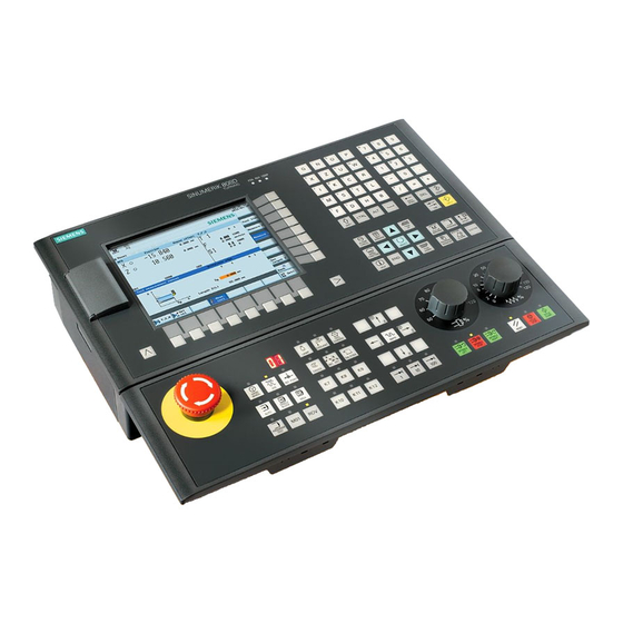
PPU version Te chnology variant Op e rator panel variant Ap plicable control system PPU151.3 Turning variant Horizontal panel, with English keys SINUMERIK 808D ADVANCED T (Turning) Horizontal panel, with Chinese keys Milling variant Horizontal panel, with English keys SINUMERIK 808D ADVANCED M (Milling) Horizontal panel, with Chinese keys PPU150.3... - Page 11 Enters the "Set-up menu" dialog box at NC startup • Enables user-defined extension applications, for example, generation of user dialog boxes with the EasyXLanguage function. For more information about this function, see the SINUMERIK 808D/SINUMERIK 808D ADVANCED Function Manual. Sta tus indicators In dicator Sta tus and meaning "POK"...
-
Page 12: Screen Layout
2.1.3 Screen layout Al arms and messages in the status area D i splays active alarms with alarm text The alarm number is displayed in white letter- ing on a red background. The associated alarm text is shown in red lettering. An arrow indicates that several alarms are active. -
Page 13: Machine Control Panels (Mcps)
All MCP variants are applicable to any of the following • control systems: Horizontal MCP, with Chinese keys and override switches • SINUMERIK 808D ADVANCED T (Turning) Vertical MCP, with English keys and a reserved slot for • • the handwheel SINUMERIK 808D ADVANCED M (Milling) •... - Page 14 Indicator off: The chip remover stops reverse rotation. K9 to K12 Reserved keys. You can define the functions of these keys in PLC Programming Tool. For more information, see the SINUMERIK 808D/SINUMERIK 808D ADVANCED Commissioning Manual. Programming and Operating Manual (Milling) 6FC5398-4DP10-0BA6, 09/2017...
- Page 15 Pre -defined labeling strips for keys of the MCP ① The MCP package includes two sets (six pieces each) of pre-defined labeling strips. One set ( as shown below) is for the ② turning variant of the control system and pre-inserted on the back of the MCP. The other set ( as shown below) is for the milling variant of the control system.
-
Page 16: Coordinate Systems
Coordinate systems As a rule, a coordinate system is formed from three mutually perpendicular coordinate axes. The positive directions of the coordinate axes are defined using the Cartesian coordinate system. The coordinate system is related to the workpiece and programming takes place independently of whether the tool or the workpiece is being traversed. When programming, it is always assumed that the tool traverses relative to the coordinate system of the workpiece, which is intended to be stationary. - Page 17 Wo rkpiece coordinate system (WCS) To describe the geometry of a workpiece in the workpiece program, a right-handed, right-angled coordinate system is also used. Generally, X0/Y0 of the WCS is set at the center, edge or corner of the workpiece while Z0 is set on the top surface of the workpiece.
-
Page 18: Protection Levels
The control system delivered by Siemens is set by default to the lowest protection level 7 (without password). If the password is no longer known, the control system must be reinitialized with the default machine/drive data. All passwords are then reset to default passwords for this software release. - Page 19 C h anging/deleting the password N o te To avoid unauthorized access to the controller, you must change the Siemens default passwords to your own ones. Select the system data operating area. If you desire to change the existing password, press this softkey to open the following win- dow and enter the new password: If you desire to delete the existing password, proceed directly to Step 6.
-
Page 20: Common Notices For Machining Operations 2
Common notices for machining operations To ensure the safety and correctness of machining, you must observe the following notices during machining operations: ● Reference point approach is required only for machine tools equipped with incremental encoders. ● Before running the spindle manually, make sure you have activated the tool. ●... -
Page 21: Setting The User Interface Language 2
Setting the user interface language N o te The default user interface language is dependent on the PPU type. For a PPU with Chinese keys, the default language is Chinese after power-on; otherwise it's English. If you desire to change it, proceed through the following operating sequence; otherwise, skip this chapter and proceed to the next chapter for setting up tools. -
Page 22: Creating/Changing A Cutting Edge
Press this softkey to confirm your settings. The window below shows the information of the new tool created. Set the desired tool data in this window. ① Column indicates the tool offset number in Siemens dialect mode. • ② Column indicates the tool offset number visible only in ISO dialect mode. -
Page 23: Activating The Tool And The Spindle
Open the menu items for cutting edge settings. Press this softkey to create a new cutting edge for the selected tool. The control system automatically adds the new cutting edge to the tool list. Now you can enter different lengths and radii for each cutting edge. You can also press the corresponding softkey to reset or delete a cutting edge. -
Page 24: Assigning The Handwheel
Press this key to move the cursor to the input field for the spindle speed, and enter the de- sired speed, for example, 1000. Press this key again to move the cursor to the input field for the spindle direction. Use this key to select the spindle direction, for example, "M3". -
Page 25: Assigning The Handwheel Through The Ppu
Press the desired axis traversing keys to assign the handwheel. Press the increment keys on the MCP to select the required override increment. 1: The override increment is 0.001 mm. • 10: The override increment is 0.010 mm. • 100: The override increment is 0.100 mm. •... - Page 26 Op e rating sequence (assigning the handwheel through the PPU) Select the machining operating area. Press this key on the MCP. Press this key to open the extended menu. Open the handwheel assignment window. Select the handwheel to be assigned with the cursor keys in the following window. You can assign a maximum of two handwheels.
-
Page 27: Measuring The Tool Manually
Measuring the tool manually N o te You must first create a tool (Page 21) and activate it (Page 23) before measuring the tool. • This section takes the milling tool measurement for example. If you have created other types of tools, proceed through •... -
Page 28: Verifying The Tool Offset Result
Switch to handwheel control mode. Select a suitable override feedrate, and then use the handwheel to move the tool to scratch the required workpiece edge (or the edge of the setting block, if it is used). Enter the distance to the workpiece edge in the X and Y directions in the "X0" and "Y0" fields respectively, for example, enter "0"... -
Page 29: Creating Part Programs 2
Creating part programs Creating a part program The control system can store a maximum of 300 part programs which include those created by the control system for certain functions such as MM+, TSM, and so on. WAR NING Ma chine malfunction due to use of insecure part programs Running an insecure part program on your machine may cause unexpected attacks to the machine, which in turn can lead to death, personal injuries, and/or machine damage. - Page 30 Press this softkey to open the window for creating a new program. Enter the name of the new program. You can enter the file name extension ".MPF" (main program) or ".SPF" (subprogram) to define the program type. The control system identifies a program as a main program if you do not enter any file name extension.
-
Page 31: Editing The Part Program
7.2.1 Using a standard program structure Using a standard program structure provides an easy way of part programming and a clear view of the machining sequences. Siemens recommends that you use the following program structure: 7.2.2 Editing a part program... - Page 32 Select the desired program file/directory in one of the following methods: Navigate to the program/directory with the cursor keys • Open the search dialog box and enter the desired search term. • N o te: If you search for a program, the file name extension must be entered in the first input field of the dialog box below.
- Page 33 When necessary, select the following vertical softkeys to complete more program editing operations. R e numbering program blocks • With this softkey, you can modify the block numbering (Nxx) of a program opened in the program editor window. After you press this softkey, the block number is inserted at the beginning of the program block in ascending order and is increased by an increment of 10 (for example, N10, N20, N30).
- Page 34 D. Place the cursor on the desired insertion point in the program and press this softkey. The content of the buffer memory is pasted. If you want to program cycles, press the corresponding softkey to open the desired cycle programming window. For more information, see Section "Cycles (Page 152)". If you want to program contours, press this softkey to open the contour programming win- dow.
- Page 35 Edit the program text in the program editor window using the following keys on the PPU: When necessary, select the following vertical softkeys to complete more program editing operations. R e numbering program blocks • With this softkey, you can modify the block numbering (Nxx) of a program opened in the program editor window.
- Page 36 C. Press this softkey to copy the selection to the buffer memory. - OR - Press this key/softkey to delete the selected program blocks and to copy them into the buff- er memory. D. Place the cursor on the desired insertion point in the program and press this softkey. The content of the buffer memory is pasted.
-
Page 37: Understanding Frequently Used Programming Instructions
N o te When you perform editing operations such as renumbering, searching, and saving of an external program file larger than 4 MB, a message appears reminding you that it will take a long time to complete the operations. To ensure that the program editor works properly, you are recommended to edit an external program file smaller than 200 MB. -
Page 38: Rapid Traverse (G00)
D e scription Il lustration Programming example G5 00 + G54: N10 G17 G90 G5 0 0 G71 With G500 ≠ 0 activated, the value in N20 T1 D1 M6 G500 is added to the value in G54. N30 S5000 M3 G94 F300 N40 G00 G5 4 X20 Y20 Z5 N50 G01 Z-2 0 N60 Z5... -
Page 39: Tool And Traverse (T, D, M6, F, G94/G95, S, M3/M4, G01)
7.2.3.4 Tool and traverse (T, D, M6, F, G94/G95, S, M3/M4, G01) D e scription Programming example T, D : N10 G17 G90 G54 G71 A new tool can be selected with the "T" command, and the "D" command N20 T1 D 1 M6 is used to activate the tool length offset. -
Page 40: Milling Circles And Arcs (G02/G03)
These two commands may cause the cutter to traverse fast around a corner or slowly at the contour. For more information, see Sections "Tool radius compensation OFF: G40 (Page 122)" and "Selecting the tool radius compensation: G41, G42 (Page 119)". 7.2.3.6 M illing circles and arcs (G02/G03) The following gives an example of machining arc with specified program code:... -
Page 41: Fixed Point Approach (G74/G75)
Start point of circle Center point of circle End point of circle Incremental distance from SP to CP in X axis Incremental distance from SP to CP in Y axis Traversing direction of the circle (clockwise) Traversing direction of the circle (counter-clockwise) For more information, see Section "Circular interpolation: G2, G3 (Page 93)". -
Page 42: Spindle Control
7.2.3.8 Spindle control D e scription Programming example M3 : N10 G17 G90 G500 G71 Spindle accelerates to the programmed speed in clockwise N20 T1 D1 M6 direction. N30 S5000 M3 G94 F300 M4 : N40 G00 X50 Y50 Z5 Spindle accelerates to the programmed speed in counter- N50 G01 Z-5 clockwise direction. -
Page 43: Simulation Prior To Machining Of The Workpiece
Simulation prior to machining of the workpiece Before machining the workpiece on the machine, you have the option of performing a quick run-through in order to graphically display how the program is executed. This provides a simple way of checking the result of the programming. Op e rating sequence Note that the following Steps 1 to 3 describe how to open a desired program file on the PPU. - Page 44 Opens the lower-level menu for the following block display options: Display all G17 blocks • Display all G18 blocks • Display all G19 blocks • Zooms in the screen from the cursor position Zooms out the screen from the cursor position Deletes all the simulation tracks recorded up till now Makes the cursor move in large or small steps Enables the material removal simulation of a defined blank...
-
Page 45: Simultaneous Recording Prior To Machining Of The Workpiece
Simultaneous recording prior to machining of the workpiece Before machining the workpiece on the machine, you can graphically display the execution of the program on the screen to monitor the result of the programming. Op e rating sequence Select the program management operating area. Enter the target program directory and position the cursor on the desired program. -
Page 46: Executing A Part Program
Machining the workpiece Executing a part program Before starting a program, make sure that both the control system and the machine are set up, and the part program is verified with simulation and test. Observe the relevant safety notes of the machine manufacturer. Select the program management operating area. -
Page 47: Executing Specified Blocks
Executing specified blocks If you would only like to perform a certain section of a program on the machine, then you do not need to start the program from the beginning. You can start the program from a specified program block in the following cases: ●... -
Page 48: Correcting A Part Program
Correcting a part program As soon as a syntax error in the part program is detected by the control system, program execution is interrupted and the syntax error is displayed in the alarm line. In this case, you can correct the error directly in the machining operating area with the program correction function. -
Page 49: Entering The Tool Wear Offsets
Entering the tool wear offsets N o te You must distinguish the direction of tool wear compensation clearly. Two methods are available for entering the tool wear offsets: absolute input and incremental input (default: absolute input). Op e rating sequence for absolute input Select the offset operating area. - Page 50 Enter the desired arithmetic statement in the input line of the pocket calculator. Press this key and the calculation result is displayed in the pocket calculator: Press this softkey to enter the result in the input field at the current cursor position and close the pocket calculator automatically.
- Page 51 Op e rating sequence for incremental input Select the offset operating area. Open the tool wear window. Position the cursor bar on the input field to be modified. Switch to incremental input. Enter the desired increment value, for example, 0.1. Positive value: the tool compensates in a direction of moving away from the workpiece.
- Page 52 Enter the desired arithmetic statement in the input line of the pocket calculator. Press this key and the calculation result (for example, 0.1) is displayed in the pocket calcu- lator: Press this softkey to add the calculation result to the value in the input field at the current cursor position and close the pocket calculator automatically.
-
Page 53: Program Control Functions
Other common operations 10.1 Program control functions You can perform further program control operations through the following operation: → 10.1.1 Program test With this softkey activated, the part program is executed with no axis or spindle movement. In this way, you can check the programmed axis positions and auxiliary function outputs of a part program. This softkey functions the same as the following key on the MCP: 10.1.2 Dry run feedrate... -
Page 54: Rapid Traverse Override
Pre conditions ● The machine manufacturer must have connected the probe to the control system. For more information, see the SINUMERIK 808D/SINUMERIK 808D ADVANCED Function Manual. ● You must first enter the radius or diameter of the tool for probe calibration. - Page 55 ① Absolute position of the probe in Z direction ② ③ The measured probe center (the machine coordinate) ④ The diameter of the probe (the measured value will be shown after calibrating) ⑤ The thickness of the probe ⑥ The measurement feedrate in "JOG" mode (this parameter is used to create the measuring program) ⑦...
-
Page 56: Measuring The Tool With A Probe (Auto)
● The machine manufacturer must parameterize special measuring functions for tool probe measuring. For more information, see the SINUMERIK 808D/SINUMERIK 808D ADVANCED Function Manual. ● You must first enter the cutting edge position and calibrate the probe (Page 54) before the actual measurement. -
Page 57: Setting Up The Workpiece
10.4 Setting up the workpiece 10.4.1 Measuring the workpiece Ove rview You must select the relevant offset panel (for example, G54) and the axis you want to determine for the offset first. Before measuring, you can start the spindle by following the steps in Section "Activating the tool and the spindle (Page 23)". Op e rating sequence Wo rkpiece edge measurement Select the machining operating area. - Page 58 Select the offset plane to save in and the measuring direction (for example, "G54" and "-"). Enter the distance (for example, "0") in the following window. Press this key or move the cursor to confirm your input. Press this vertical softkey. The workpiece offset of the X axis is calculated automatically and displayed in the offset field.
-
Page 59: Entering/Modifying Workpiece Offsets
C i rcular workpiece measurement Select the machining operating area. Switch to "JOG" mode. Open the lower-level menu for workpiece measurement. Open the window for measurement of a circular workpiece. Traverse the tool, which has been measured previously, in the direction of the orange arrow P1 shown in the measuring window, in order to scratch the workpiece edge with the tool tip. -
Page 60: Entering/Modifying The Setting Data
Use the cursor keys to position the cursor bar in the input fields to be modified and enter the values. Confirm your entries. The changes to the workpiece offsets are activated immediately. 10.5 Entering/modifying the setting data En tering/modifying the setting data Op e rating sequence Select the offset operating area. - Page 61 Se tting the time counter Op e rating sequence Select the offset operating area. Open the setting data window. Open the time counter window. Position the cursor bar in the input fields to be modified and enter the values (see table below for the parameter descriptions).
- Page 62 Se tting the working area limitation Op e rating sequence Select the offset operating area. Open the setting data window. Open the working area limitation window. Position the cursor on the input field to be modified and enter the required value. Position the cursor on the checkbox for value activation located after the input field.
-
Page 63: Setting R Parameters
Select a group of setting data you desire to modify. Press these softkeys to search for your desired setting data with the data number/name. Alternatively, you can position the cursor on the input field to be modified and enter the desired value. -
Page 64: Setting User Data
10.7 Setting user data Fu n ctionality The "User data" start screen lists the user data that exist within the control system. You can set or query these global parameters in any program as required. Op e rating sequence Select the offset operating area. Open the list of user data. -
Page 65: Configuring The Operating Area After Startup
10.9 Configuring the operating area after startup The machining operating area is displayed by default after the startup of the control system. Alternatively, you can select another operating area which you desire to enter after the system starts up. Op e rating sequence Select the system data operating area. -
Page 66: Executing From External (Through Usb Interface)
10.10.1.1 Ex ecuting from external (through USB interface) Pre requisite: A USB memory stick (which includes the part program to be executed) is inserted in the front USB interface of the PPU. Proceed as follows to execute a part program from external through the USB interface: Select the program management operating area. -
Page 67: Transferring From External (Through Usb Interface)
10.10.1.2 Transferring from external (through USB interface) Pre requisite: A USB memory stick (which includes the part program to be transferred) is inserted in the front USB interface of the PPU. Proceed as follows to transfer a part program from external through the USB interface: Select the program management operating area. - Page 68 Establishing a network connection Proceed as follows to establish a network connection: Connect the control system with the local network using an Ethernet cable. Select the system data operating area on the PPU. Press the extension key. Enter the main screen of the service control options through the following softkey opera- tions: →...
- Page 69 C reating and connecting a network drive Proceed as follows to create and connect a network drive: Share a directory on your local disk on your computer. Select the program management operating area. Press this softkey to go to the network drive directory. Press this softkey to go to the window for configuring the network drives.
-
Page 70: Executing From External (Through Ethernet Connection)
10.10.2.2 Ex ecuting from external (through Ethernet connection) Pre requisites: ● An Ethernet connection has been established between the control system and the computer. ● A network drive (which includes the part program to be executed) has been created and connected. Proceed as follows to execute a part program from external through the Ethernet connection: Select the program management operating area. -
Page 71: Configuring The Firewall
Select the desired network drive (which includes the part program to be transferred) and press this key to open it. Select the program file you desire to transfer. Press this softkey to copy the file to the buffer memory on the control system. Enter the program directory. -
Page 72: Extending/Deactivating The Cnc Lock Function
WAR NING N e twork security risks due to improper firewall configuration Improper firewall configuration may cause network security risks, for example, data leakage, virus invasion, and hacker attack. This may lead to incorrect parameterization or machine malfunction, which in turn can result in death, severe injuries and/or property damage. - Page 73 CNC lock function extended (with a new lock date): • CNC lock function deactivated (with no lock date): • N o te If an error occurs when importing the activation file, an error-specific alarm will be issued. The state of the CNC lock function remains unchanged.
-
Page 74: Data Backup
10.12 Data backup 10.12.1 Internal data backup You can save the NC and PLC data of the volatile memory to the permanent memory of the control system. N o te After changing important data, it is recommended to carry out an internal data backup immediately. Ba cking up data internally Pre requisite: ●... -
Page 75: External Data Backup
N o te The following message is displayed on the screen after the control system starts up successfully with the saved data: You must enter the password again after you have powered up the control system with the saved data. 10.12.2 External data backup 10.12.2.1 External data backup in a data archive... -
Page 76: External Data Backup Of Separate Files
N o te Do not remove the USB stick in the process of data backup if you choose USB as the target directory. Pressing <CTRL + S> when you are in any operating area creates a startup archive on the connected USB stick. In addition, it automatically saves the action log to the USB stick. -
Page 77: Pocket Calculator
Backs up the files in the folder for storing end user files on the control system. Press this softkey to paste the copied data into the current directory. For more information about data backup, refer to the SINUMERIK 808D/SINUMERIK 808D ADVANCED Diagnostics Manual. -
Page 78: Fundamentals Of Programming
C h aracters that may be entered +, -, *, / Basic arithmetic operations Sine function The X value (in degrees) in front of the input cursor is replaced by the sin(X) value. Cosine function The X value (in degrees) in front of the input cursor is replaced by the cos(X) value. Square function The X value in front of the input cursor is replaced by the X value. -
Page 79: Program Structure
Example 11.1.2 Program structure Structure and content The NC program consists of a sequence of b l ocks (see the table below). Each block represents a machining step. Instructions are written in the blocks in the form of w o rds. The last block in the execution sequence contains a special word for the end of the program, for example, M2 . -
Page 80: Plane Selection: G17 To G19
● Incremental dimension, X=IC(value) only this value applies exclusively for the stated axis and is not influenced by G90/G91. This is possible for all axes and also for SPOS, SPOSA spindle positionings, and interpolation parameters I, J, ● Inch dimension, G70 applies for all linear axes in the block, until revoked by G71 in a following block. ●... -
Page 81: Absolute/Incremental Dimensioning: G90, G91, Ac, Ic
11.2.3 Absolute/incremental dimensioning: G90, G91, AC, IC Fu n ctionality With the instructions G90/G91, the written positional data X, Y, Z... are evaluated as a coordinate point (G90) or as an axis position to traverse to (G91). G90/G91 applies to all axes. Irrespective of G90/G91, certain positional data can be specified for certain blocks in absolute/incremental dimensions using AC/IC. -
Page 82: Dimensions In Metric Units And Inches: G71, G70, G710, G700
11.2.4 Dimensions in metric units and inches: G71, G70, G710, G700 Fu n ctionality If workpiece dimensions that deviate from the base system settings of the control system are present (inch or mm), the dimensions can be entered directly in the program. The required conversion into the base system is performed by the control system. - Page 83 Po lar angle AP=... The angle is always referred to the horizontal axis (abscissa) of the plane (for example, with G17: X axis). Positive or negative angle specifications are possible. The polar angle remains stored and must only be written in blocks in which it changes, after changing the pole or when switching the plane.
-
Page 84: Programmable Work Offset: Trans, Atrans
11.2.6 Programmable work offset: TRANS, ATRANS Fu n ctionality The programmable work offset can be used: ● for recurring shapes/arrangements in various positions on the workpiece ● when selecting a new reference point for the dimensioning ● as a stock allowance when roughing This results in the current workpiece coordinate system. -
Page 85: Programmable Rotation: Rot, Arot
11.2.7 Programmable rotation: ROT, AROT Fu n ctionality The rotation is performed in the current plane G17 or G18 or G19 using the value of RPL=... specified in degrees. Programming ROT RPL=... ; Programmable rotation, deletes old instructions for offsetting, rotation, scaling factor, mirroring AROT RPL=... -
Page 86: Programmable Scale Factor: Scale, Ascale
11.2.8 Programmable scale factor: SCALE, ASCALE Fu n ctionality A scale factor can be programmed for all axes with SCALE/ASCALE. The path is enlarged or reduced by this factor in the axis specified. The currently set coordinate system is used as the reference for the scale change. Programming SCALE X... -
Page 87: Programmable Mirroring: Mirror, Amirror
11.2.9 Programmable mirroring: MIRROR, AMIRROR Fu n ctionality MIRROR and AMIRROR can be used to mirror workpiece shapes on coordinate axes. All traversing motions of axes for which mirroring is programmed are reversed in their direction. Programming MIRROR X0 Y0 Z0 ;... -
Page 88: Workpiece Coordinate System - Settable Work Offset: G54 To G59, G500, G53, G153
11.2.10 Workpiece coordinate system - settable work offset: G54 to G59, G500, G53, G153 Fu n ctionality The settable work offset specifies the position of the w o rkpiece zero on the machine (offset of the workpiece zero with respect to the machine zero). This offset is determined upon clamping of the workpiece into the machine and must be entered in the corresponding data field by the operator. -
Page 89: Nc Block Compression (Compon, Compcurv, Compcad)
Programming example N10 G54 ; Call first settable work offset N20 L47 ; Machining of workpiece 1, here using L47 N30 G55 ; Call second settable work offset N40 L47 ; Machining of workpiece 2, here using L47 N50 G56 ;... - Page 90 Su pplementary conditions ● The NC block compression is generally executed for linear blocks (G1). ● Only blocks that comply with a simple syntax are compressed: N... G1X... Y... Z... F... ;comment All other blocks are executed unchanged (no compression). ●...
-
Page 91: Linear Interpolation
11.3 Linear interpolation 11.3.1 Linear interpolation with rapid traverse: G0 Fu n ctionality The rapid traverse movement G0 is used for rapid positioning of the tool, but not for d i rect workpiece machining. All the axes can be traversed simultaneously - on a straight path. For each axis, the maximum speed (rapid traverse) is defined in machine data. -
Page 92: Feedrate F
11.3.2 Feedrate F Fu n ctionality The feed F is the p a th velocity and represents the value of the geometric sum of the velocity components of all axes involved. The individual axis velocities therefore result from the portion of the axis path in the overall distance to be traversed. -
Page 93: Circular Interpolation
See the illustration for linear interpolation in three axes using the example of a slot: Programming example N05 G0 G90 X40 Y48 Z2 S500 M3 ; The tool traverses in rapid traverse on P1, three axes concurrently, spindle speed = 500 rpm, clockwise N10 G1 Z-12 F100 ;... - Page 94 The description of the desired circle can be given in various ways: See the following illustration for possibilities of circle programming with G2/G3 using the example of the axes X/Y and G2: G2/G3 remains active until canceled by another instruction from this G group (G0, G1, ...). The p a th velocity is determined by the programmed F word.
- Page 95 See the following illustration for selection of the circle from two possible circles with radius specification: Programming example: Definition of center point and end point N5 G90 X30 Y40 ; Starting point circle for N10 N10 G2 X50 Y40 I10 J-7 ;...
- Page 96 Programming example: End point and radius specification N5 G90 X30 Y40 ; Starting point circle for N10 N10 G2 X50 Y40 CR=12.207 ; End point and radius N o te With a negative leading sign for the value with CR=-..., a circular segment larger than a semi-circle is selected. Programming example: Definition of end point and aperture angle N5 G90 X30 Y40 ;...
- Page 97 Programming example: Definition of center point and aperture angle N5 G90 X30 Y40 ; Starting point circle for N10 N10 G2 I10 J-7 AR=105 ; Center point and aperture angle N o te Center point values refer to the circle starting point! Programming example: Polar coordinates N1 G17 ;...
-
Page 98: Circular Interpolation Via Intermediate Point: Cip
11.4.2 Circular interpolation via intermediate point: CIP Fu n ctionality If you know th ree contour points of the circle, instead of center point or radius or aperture angle, then it is advantageous to use the CIP function. The direction of the circle results here from the position of the intermediate point (between starting and end points). The intermediate point is written according to the following axis assignment: I1=... -
Page 99: Circle With Tangential Transition: Ct
11.4.3 Circle with tangential transition: CT Fu n ctionality With CT and the programmed end point in the current plane G17 through G19, a circle is generated which is connected tangentially to the previous path segment (circle or straight line) in this plane. This defines the radius and center point of the circle from the geometric relationships of the previous path section and the programmed circle end point. -
Page 100: Feedrate Override For Circles: Cftcp, Cfc
See the following illustration for helical interpolation: Programming example N10 G17 ; X/Y plane, Z standing vertically on it N20 G0 Z50 N30 G1 X0 Y50 F300 ; Approach starting point N40 G3 X0 Y0 Z33 I0 J-25 TURN= 3 ;... -
Page 101: Thread Cutting
See the following illustration for feedrate override G901 with internal/external machining: C o rrected feedrate ● External machining: ) / r corr. prog. cont tool cont ● Internal machining: ) / r korr. prog. cont tool cont : Radius of the circle contour cont : Tool radius tool... -
Page 102: Tapping With Compensating Chuck: G63
N o te A complete cycle of tapping with compensating chuck is provided by the standard cycle CYCLE840. See the following illustration for tapping using G33: Programming example ; metric thread 5, ; pitch as per table: 0.8 mm/rev., hole already premachined N10 G54 G0 G90 X10 Y10 Z5 S600 M3 ;... -
Page 103: Thread Interpolation: G331, G332
N o te The standard cycle CYCLE840 provides a complete tapping cycle with compensating chuck (but with G33 and the relevant prerequisites). See the following illustration for tapping using G63: Programming example ; metric thread 5, ; lead as per table: 0.8 mm/rev., hole already premachined N10 G54 G0 G90 X10 Y10 Z5 S600 M3 ;... -
Page 104: Fixed Point Approach
See the following illustration for tapping using G331/G332: Axi s velocity When programming with G331/G332, you can determine the axis velocity based on the spindle speed and the thread lead. However, the maximum axis velocity (rapid traverse) defined in the machine data cannot be exceeded; otherwise, alarms will appear. -
Page 105: Reference Point Approach: G74
C ommand Si gnificance Fixed point approach FP=<n> Fixed point that is to be approached. The fixed point number is specified: <n> Value range of <n>: 1, 2, 3, 4 MD30610$NUM_FIX_POINT_POS should be set if fixed point number 3 or 4 is to be used. If no fixed point is specified, fixed point 1 is approached automatically. -
Page 106: Exact Stop/Continuous-Path Control Mode: G9, G60, G64
See the following illustration for basic course of the path velocity when using BRISK/SOFT: Programming BRISK ; Jerking path acceleration SOFT ; Jerk-limited path acceleration Programming example N10 SOFT G1 X30 Z84 F650 ; Jerk-limited path acceleration N90 BRISK X87 Z104 ;... - Page 107 See the following illustration for exact stop window coarse or fine, in effect for G60/G9: Programming example N5 G602 ; Exact stop window coarse N10 G0 G60 X20 ; Exact stop modal N20 X30 Y30 ; G60 continues to act N30 G1 G601 X50 Y50 F100 ;...
-
Page 108: Dwell Time: G4
See the following illustration for comparison of the G60 and G64 velocity behavior: 11.7.3 Dwell time: G4 Fu n ctionality Between two NC blocks, you can interrupt the machining for a defined time by inserting a se parate block with G4; e.g. for relief cutting. -
Page 109: Spindle Movements
11.8 Spindle movements 11.8.1 Gear stages Fu n ction Up to 5 gear stages can be configured for a spindle for speed/torque adaptation. The selection of a gear stage takes place in the program via M commands (see Section "Miscellaneous function M (Page 125)"): ●... -
Page 110: Spindle Positioning: Spos
11.8.3 Spindle positioning: SPOS Fu n ctionality R e quirement: The spindle must be technically designed for position control. With the function SPOS= you can position the spindle in a specific a n gular position. The spindle is held in the position through position control. - Page 111 An gle ANG If only one end point coordinate of the plane is known for a straight line or for contours across multiple blocks the cumulative end point, an angle parameter can be used for uniquely defining the straight line path. The angle is always referred to the abscissa of the current plane G17 to G19, e.g.
-
Page 112: Rounding, Chamfer
11.9.2 Rounding, chamfer Fu n ctionality You can insert the chamfer (CHF or CHR) or rounding (RND) elements into a contour corner. If you wish to round several contour corners sequentially by the same method, use "Modal rounding" (RNDM). You can program the feedrate for the chamfer/rounding with FRC (non-modal) or FRCM (modal). If FRC/FRCM is not programmed, the normal feedrate F is applied. - Page 113 C h amfer CHF or CHR A linear contour element is inserted between l inear and circle contours in any combination. The edge is broken. See the following illustration for inserting a chamfer with CHF using the example: Between two straight lines. See the following illustration for inserting a chamfer with CHR using the example: Between two straight lines.
- Page 114 R o unding RND or RNDM A circle contour element can be inserted with tangential connection between the l i near and circle contours in any combination. See the following examples for inserting roundings: Programming examples for rounding N10 G17 G94 F300 G0 X100 Y100 N20 G1 X85 RND=8 ;...
-
Page 115: Tool And Tool Offset
11.10 Tool and tool offset 11.10.1 General Information Fu n ctionality When creating programs for machining workpieces, it is not necessary to take into account the tool length or the tool radius. You program the workpiece dimensions directly, for example following the drawing. You enter the tool data separately in a special data section. -
Page 116: Tool T
11.10.2 Tool T Fu n ctionality The tool selection takes place when the T word is programmed. Whether this is a to ol change or only a p reselection, is defined in the machine data: ● The tool change (tool call) is performed either directly using the T word or ●... - Page 117 In formation The to ol length compensations are effective i mmediately once the tool is active - if no D number has been programmed - with the values of D1. The offset is applied with the first programmed traverse of the respective length offset axis. Observe any active G17 to G19. A to o l radius compensation must also be activated by G41/G42.
- Page 118 To ol special cases For the tool types 'cutter' and 'drill', the parameters for length 2 and length 3 are only required for special cases (e.g. multi- dimensional length offset for an angle head construction). See the following illustration for effect of the tool length compensation - 3D (special case): See the following illustration for effect of the offsets with the tool type 'drill': See the following illustration for effect of the offsets with the tool type 'cutter': Programming and Operating Manual (Milling)
-
Page 119: Selecting The Tool Radius Compensation: G41, G42
11.10.4 Selecting the tool radius compensation: G41, G42 Fu n ctionality The control system is working with tool radius compensation in the selected plane G17 to G19. A tool with a corresponding D number must be active. The tool radius compensation is activated by G41/G42. The control system automatically calculates the required equidistant tool paths for the programmed contour for the respective current tool radius. - Page 120 Sta rting the compensation The tool travels in a straight line directly to the contour and is positioned perpendicular to the path tangent at the starting point of the contour. Select the starting point such that a collision-free travel is ensured. See the following illustration for start of the tool radius compensation with G42 as example: The tool tip goes around the left of the workpiece when the tool runs clockwise using G41;...
-
Page 121: Corner Behavior: G450, G451
11.10.5 Corner behavior: G450, G451 Fu n ctionality By using the functions G450 and G451, you can set the behavior for a non-continuous transition from one contour element to another contour element (corner behavior) when G41/G42 is active. The internal and external corners are detected by the control system itself. For internal corners, the intersection of the equidistant paths is always approached. -
Page 122: Tool Radius Compensation Off: G40
In this case, the control system switches to transition circle for this block automatically if a certain set angle value (100°) is reached. See the following illustration for acute contour angle and switching to transition circle: 11.10.6 Tool radius compensation OFF: G40 Fu n ctionality The compensation mode (G41/G42) is deselected with G40. -
Page 123: Special Cases Of The Tool Radius Compensation
Programming example N10 G0 X20 Y20 T1 D1 M3 S500 N20 G41 G1 X10 Y10 F100 N30 G2 X20 Y20 CR=20 ; Last block on the contour, circle or straight line, P1 N40 G40 G1 X10 Y10 ; Switch off tool radius compensation, P2 N50 M30 11.10.7 Special cases of the tool radius compensation... -
Page 124: Example Of Tool Radius Compensation
Acu te contour angles If very sharp outside corners occur in the contour with active G451 intersection, the control system automatically switches to transition circle. This prevents long idle motions. 11.10.8 Example of tool radius compensation See the following illustration for example of tool radius compensation: Programming example N1 T1 ;... -
Page 125: Miscellaneous Function M
11.11 Miscellaneous function M Fu n ctionality The miscellaneous function M initiates switching operations, such as "Coolant ON/OFF" and other functions. A small part of M functions have already been assigned a fixed functionality by the CNC manufacturer. The functions not yet assigned fixed functions are reserved for free use of the machine manufacturer. -
Page 126: Arithmetic Parameters, Lud And Plc Variables
N o te In addition to the M and H functions, T, D and S functions can also be transferred to the PLC (Programmable Logic Controller). In all, a maximum of 10 function outputs of this type are possible in a part program block. 11.13 Arithmetic parameters, LUD and PLC variables 11.13.1... -
Page 127: Local User Data (Lud)
Ari thmetic operations/arithmetic functions When operators/arithmetic functions are used, it is imperative to use the conventional mathematical notation. Machining priorities are set using the round brackets. Otherwise, multiplication and division take precedence over addition and subtraction. Degrees are used for the trigonometric functions. Permitted arithmetic functions: see Section "List of instructions (Page 327)"... -
Page 128: Reading And Writing Plc Variables
Each data type requires its own program line. However, several variables of the same type can be defined in one line. Example: DEF INT PVAR1, PVAR2, PVAR3=12, PVAR4 ;4 type INT variables Example for STRING type with assignment: DEF STRING[12] PVAR="Hello" ;... -
Page 129: Program Jumps
11.14 Program jumps 11.14.1 Unconditional program jumps Fu n ctionality NC programs process their blocks in the sequence in which they were arranged when they were written. The processing sequence can be changed by introducing program jumps. The jump destination can be a block with a l a bel or with a b l ock number. This block must be located within the program. The unconditional jump instruction requires a separate block. - Page 130 Label ;Selected string for the label (jump label) or block number ;Introduction of the jump condition Condition ;Arithmetic parameter, arithmetic expression for formulating the condition C omparison operations Op e rators Me aning Equal to < > Not equal to >...
-
Page 131: Program Example For Jumps
11.14.3 Program example for jumps Ta sk Approaching points on a circle segment: Existing conditions: Start angle: 30° in R1 Circle radius: 32 mm in R2 Position spacing: 10° in R3 Number of points: 11 in R4 Position of circle center in Z: 50 mm in R5 Position of circle center in X: 20 mm in R6 See the following illustration for linear approach of points on a circle segment: Programming example... -
Page 132: Jump Destination For Program Jumps
11.14.4 Jump destination for program jumps Fu n ctionality A l a bel or a b l ock number serve to mark blocks as jump destinations for program jumps. Program jumps can be used to branch to the program sequence. Labels can be freely selected, but must contain a minimum of 2 and a maximum of 8 letters or numbers of which the first two ch aracters must be letters or underscore characters. - Page 133 See the following illustration for example of sequence when calling a subroutine twice: Su broutine name The program is given a unique name allowing it to be selected from several subroutines. When you create the program, the program name may be freely selected, provided the following conventions are observed. The same rules apply as for the names of main programs.
-
Page 134: Calling Machining Cycles
Please make sure that the values of your arithmetic parameters used in upper program levels are not inadvertently changed in lower program levels. When working with SIEMENS cycles, up to 4 program levels are needed. 11.15.2 Calling machining cycles Fu n ctionality Cycles are technology subroutines realizing a certain machining process generally, for example, drilling or milling. -
Page 135: Executing Internal And External Subroutines (Call, Extcall)
11.15.4 Executing internal and external subroutines (CALL, EXTCALL) Fu n ction ● With the command, you can reload and execute programs stored in the NC directory. CALL ● With the command, you can reload and execute programs stored on an external USB memory stick. EXTCALL Ma chine data and setting data The following machine data is used for the... -
Page 136: Timers And Workpiece Counters
N o te Internal and external subroutines must not contain jump statements such as , or GOTOF GOTOB CASE LOOP WHILE REPEAT constructions are possible. IF-ELSE-ENDIF Subroutine calls and nested calls may be used. CALL EXTCALL R ESET, POWER ON RESET and POWER ON can cause the interruption of internal and external subroutine calls. - Page 137 Ti mers that are activated via machine data The following timers are activated via machine data (default setting). Each active run-time measurement is automatically interrupted in the stopped program state or for feedrate-override-zero. The behavior of the activated timers for active dry run feedrate and program testing can be specified using machine data. ●...
-
Page 138: Workpiece Counter
① ⑤ = $AC_TOTAL_PARTS = $AC_CYCLE_TIME ② ⑥ = $AC_REQUIRED_PARTS = $AC_CUTTING_TIME ③ =$AC_ACTUAL_PARTS ⑦ = $AN_SETUP_TIME $AC_SPECIAL_PARTS is not available for display. ④ = $AC_OPERATING_TIME ⑧ = $AN_POWERON_TIME You can also view the time counter information through the following operating area: →... -
Page 139: Smooth Approach And Retraction
D i splay The content of the active system variables is visible on the window opened through the following key operations: → → Wi ndow display: ① = $AC_TOTAL_PARTS ⑤ = $AC_CYCLE_TIME ② = $AC_REQUIRED_PARTS ⑥ = $AC_CUTTING_TIME ③ =$AC_ACTUAL_PARTS ⑦... - Page 140 G248 ; Retraction with a quadrant G347 ; Approach with a semi-circle G348 ; Retraction with a semi-circle G340 ; Approach and retraction in space (basic setting) G341 ; Approach and retraction in the plane DISR=... ; Approach and retraction with straight lines (G147/G148): Distance of the cutter edge from the start or end point of the contour ;...
- Page 141 See the following illustration for approaching along a quadrant using the example of G42 or retraction using G41 and completion with G40: Programming example: Approach/retraction along a quarter in a plane N10 T1 D1 G17 ; Activate tool, X/Y plane N20 G0 X20 Y20 ;...
- Page 142 C o ntrolling the infeed motion using DISCL and G340, G341 DISCL=... specifies the distance of point P2 from the machining plane (see following figure). In the case DISCL=0, the following will apply: ● With G340: The whole approach motion consists only of two blocks (P1, P2 and P3 are identical). The approach contour is generated from P3 to P4.
- Page 143 This feedrate is active from P3 or P2 if FAD is not programmed. If no F word is programmed in the SAR block, the velocity of the previous block will act. ● Programming using FAD: Specify the feedrate for – G341: Infeed motion vertically to the machining plane from P2 to P3 –...
-
Page 144: Cylinder Surface Transformation (Tracyl)
11.18 Cylinder surface transformation (TRACYL) Fu n ctionality ● The TRACYL cylinder surface transformation function can be used to machine: – Longitudinal grooves on cylindrical bodies – Transverse grooves on cylindrical objects – Grooves with any path on cylindrical bodies The path of the grooves is programmed with reference to the unwrapped, level surface of the cylinder. - Page 145 Programming TRACYL(d) or TRACYL(d, n) or for transformation type 514 TRACYL(d, n, groove side offset) TRAFOOF R o tary axis The rotary axis cannot be programmed as it is occupied by a geometry axis and thus cannot be programmed directly as channel axis.
- Page 146 Example: Tool definition The following example is suitable for testing the parameterization of the TRACYL cylinder transformation: Program code Comment Tool parameters Meaning Number (DP) $TC_DP1[1,1]=120 Tool type (Milling tool) $TC_DP2[1,1]=0 Cutting edge position (Only for turning tools) Program code Comment Geometry Length compensation...
- Page 147 Ma chining a hook-shaped groove: Program code Comment N90 G1 Y0 Z-10 ; Approach starting position N100 G42 OFFN=-4.5 ; Tool radius compensation right of contour on N110 X19 F500 N120 Z-25 N130 Y30 N140 OFFN=-3.5 N150 Y0 N160 Z-10 N170 X25 N180 TRAFOOF N190 DIAMON...
- Page 148 Certain machine data settings are assumed for the part program and the assignment of the corresponding axes in the BCS or MCS. For more information, see the SINUMERIK 808D/SINUMERIK 808D ADVANCED Function Manual. Programming and Operating Manual (Milling) 6FC5398-4DP10-0BA6, 09/2017...
- Page 149 Offset contour normal OFFN (transformation type 513) To mill grooves with TRACYL, the following is programmed: ● Groove center line in the part program ● Half the groove width programmed using OFFN. To avoid damage to the groove side OFFN acts only when the tool radius compensation is active. Furthermore, OFFN should also be >= the tool radius to avoid damage occurring to the opposite side of the groove.
-
Page 150: Coupled Motion (Trailon, Trailof)
● It is possible to change OFFN within a part program. This could be used to shift the groove center line from the center (see diagram). ● Guiding grooves: TRACYL does not create the same groove for guiding grooves as it would be with a tool with the diameter producing the width of the groove. - Page 151 <coupling factor> Parameter 3: Coupling factor The coupling factor specifies the desired relationship between the paths of the coupled- motion axis and the leading axis: <coupling factor> = path of coupled-motion axis/path of leading axis. Type: REAL Default: 1 The input of a negative value causes the leading axis and the coupled-motion axis to traverse in opposite direction.
-
Page 152: Overview Of Cycles
D ynamics limit If a coupled axis group is activated in the part program, the dynamic response of all coupled-motion axes is taken into account during traversing of the leading axis to avoid overloading the coupled-motion axes. C o upling status The coupling status of an axis can be checked in the part program with the system variable: $AA_COUP_ACT[<axis>]. -
Page 153: Programming Cycles
POCKET4: Circular pocket milling (with any milling tool) CYCLE90: Thread milling CYCLE832: High speed settings 12.2 Programming cycles C a ll and return conditions The G functions effective prior to the cycle call and the programmable offsets remain active beyond the cycle. The machining level (G17, G18, G19) must be defined before calling the cycle. -
Page 154: Graphical Cycle Programming In The Program Editor
Ba sic instructions with regard to the assignment of standard cycle parameters Each defining parameter of a cycle has a certain data type. The parameter being used must be specified when the cycle is called. In this parameter list, the following parameters can be transferred: ●... -
Page 155: Drilling Cycles
Enter the values directly (numerical values) or indirectly (R parameters, for example, R27, or expressions consisting of R parameters, for example, R27 + 10). If numerical values are entered, then the control system automatically performs a check to see whether the value lies within the permitted range. Use this key to select values for some parameters that may have only a few values for se- lection. -
Page 156: Requirements
See the following illustration for drilling, centering - CYCLE81: The machining parameters have a different meaning and effect in the individual cycles. They are therefore programmed in each cycle separately. 12.4.2 Requirements C a ll and return conditions Drilling cycles are programmed independently of the actual axis names. The drilling position must be approached in the higher-level program before the cycle is called. -
Page 157: Drilling, Centering - Cycle81
D w ell time programming The parameters for dwell times in the drilling cycles are always assigned to the F word and must therefore be assigned with values in seconds. Any deviations from this procedure must be expressly stated. 12.4.3 Drilling, centering - CYCLE81 Programming CYCLE81 (RTP, RFP, SDIS, DP, DPR) - Page 158 N o te If a value is entered both for DP and for DPR, the final drilling depth is derived from DPR. If this differs from the absolute depth programmed via DP, the message "Depth: Corresponding to value for relative depth" is output in the dialog line. If the values for reference and retraction planes are identical, a relative depth specification is not permitted.
-
Page 159: Drilling, Counterboring - Cycle82
12.4.4 Drilling, counterboring - CYCLE82 Programming CYCLE82 (RTP, RFP, SDIS, DP, DPR, DTB) Pa rameters Pa rameter D a ta type D e scription REAL Retraction plane (absolute) REAL Reference plane (absolute) SDIS REAL Safety clearance (enter without sign) REAL Final drilling depth (absolute) REAL Final drilling depth relative to the reference plane (enter without sign) - Page 160 D TB (dwell time) The dwell time to the final drilling depth (chip breakage) is programmed under DTB in seconds. Programming example 1: Drilling_counterboring The program machines a single hole of a depth of 27 mm at position X24 Y15 in the XY plane with cycle CYCLE82. The dwell time programmed is 2 s, the safety clearance in the drilling axis Z is 4 mm.
-
Page 161: Deep-Hole Drilling - Cycle83
Confirm your settings with this softkey. The cycle is then automatically transferred to the program editor as a separate block. 12.4.5 Deep-hole drilling - CYCLE83 Programming CYCLE83 (RTP, RFP, SDIS, DP, DPR, FDEP, FDPR, DAM, DTB, DTS, FRF, VARI, AXN, MDEP, VRT, DTD, DIS1) Pa rameters Pa rameter D a ta type... - Page 162 Pa rameter D a ta type D e scription REAL Dwell time at starting point and for chip removal Values: >0: in seconds <0: in revolutions REAL Feedrate factor for the first drilling depth (enter without sign) Range of values: 0.001 ... 1 VARI Machining type: Chip breakage=0, Chip removal=1 Tool axis (values: 1 = 1st geometrical axis;...
- Page 163 See the following illustration for parameters for CYCLE83: D e ep-hole drilling with chip breakage (VARI=0) ● Approach of the reference plane brought forward by the safety clearance by using G0 ● Traversing to the first drilling depth with G1, the feedrate for which is derived from the feedrate defined with the program call which is subject to parameter FRF (feedrate factor) ●...
- Page 164 In terrelation o f the DP (or DPR), FDEP (or FDPR) and DAM parameters The intermediate drilling depth is calculated in the cycle on the basis of final drilling depth, first drilling depth and amount of degression as follows: ● In the first step, the depth parameterized with the first drilling depth is traversed as long as it does not exceed the total drilling depth ●...
- Page 165 VR T (variable retraction value for chip breakage with VARI=0) You can program the retraction path for chip breaking. D TD (dwell time at final drilling depth) The dwell time at final drilling depth can be entered in seconds or revolutions. D IS1 (programmable limit distance for VARI=1) The limit distance after re-insertion in the hole can be programmed.
-
Page 166: Rigid Tapping - Cycle84
Programming example 2: Deep-hole drilling Proceed through the following steps: Select the desired operating area. Open the vertical softkey bar for available drilling cycles. Press this softkey to open the window for CYCLE83. Parameterize the cycle as desired. Confirm your settings with this softkey. The cycle is then automatically transferred to the program editor as a separate block. - Page 167 Pa rameter D a ta type D e scription SDAC Direction of rotation after end of cycle Values: 3, 4 or 5 (for M3, M4 or M5) MPIT REAL Thread lead as a thread size (signed): Range of values 3 (for M3) to 48 (for M48); the sign determines the direction of rotation in the thread REAL Thread lead as a value (signed)
- Page 168 Explanation of the parameters For more information about the parameters RTP, RFP, SDIS, DP, DPR, see Section "Drilling, centering - CYCLE81 (Page 157)". D TB (dwell time) The dwell time must be programmed in seconds. When tapping blind holes, it is recommended that you omit the dwell time. SD AC (direction of rotation after end of cycle) Under SDAC, the direction of rotation after end of cycle is programmed.
- Page 169 For example, to machine a center hole (in Z) in the G17 plane, you program: AXN=3 D e ep-hole tapping: VARI, DAM, VRT With the VARI parameter, it is possible to distinguish between simple tapping (VARI = 0) and deep-hole tapping (VARI ≠ 0). In conjunction with deep-hole tapping, it is possible to choose between chip breaking (retraction by variable distance from current drilling depth, parameter VRT, VARI = 1) and chip removal (withdrawal from reference plane VARI = 2).
-
Page 170: Tapping With Compensating Chuck - Cycle840
Programming example 2: Rigid tapping Proceed through the following steps: Select the desired operating area. Open the vertical softkey bar for available drilling cycles. Press this softkey from the vertical softkey bar. Press this softkey to open the window for CYCLE84. Parameterize the cycle as desired. Confirm your settings with this softkey. - Page 171 Pa rameter D a ta type D e scription REAL Final drilling depth relative to the reference plane (enter without sign) REAL Dwell time at final drilling depth (chip breakage) Direction of rotation for retraction Values: 0 (automatic direction reversal), 3 or 4 (for M3 or M4) SDAC Direction of rotation after end of cycle Values: 3, 4 or 5 (for M3, M4 or M5)
- Page 172 Se quence of operations Ta pping with compensating chuck with encoder Position reached prior to cycle start: The drilling position is the position in the two axes of the selected plane. The cycle creates the following sequence of motions: ● Approach of the reference plane brought forward by the safety clearance by using G0 ●...
- Page 173 The value for the thread lead can be defined either as the thread size (for metric threads between M3 and M48 only) or as a value (distance from one thread turn to the next as a numerical value). Any parameters not required are omitted in the call or assigned the value zero.
- Page 174 N10 G90 G0 T11 D1 S500 M3 ; Specification of technology values N20 G17 X35 Y35 Z60 ; Approach drilling position N30 G1 F200 ; Setting the path feedrate N40 CYCLE840(20,0,3,-15,,1,4,3,1,6,,3) Cycle call, dwell time 1 s, direction of rotation for retraction M4, direction of rotation after cycle M3, no safety clear- ance, parameters MPIT and PIT have been omitted...
-
Page 175: Reaming 1 - Cycle85
12.4.8 Reaming 1 - CYCLE85 Programming CYCLE85 (RTP, RFP, SDIS, DP, DPR, DTB, FFR, RFF) Pa rameters Pa rameter D a ta type D e scription REAL Retraction plane (absolute) REAL Reference plane (absolute) SDIS REAL Safety clearance (enter without sign) REAL Final drilling depth (absolute) REAL... -
Page 176: Boring - Cycle86
D TB (dwell time) The dwell time to the final drilling depth is programmed under DTB in seconds. FFR (feedrate) The feedrate value programmed under FFR is active in drilling. R FF (retraction feedrate) The feedrate value programmed under RFF is active when retracting from the hole to the reference plane + safety clearance. - Page 177 Fu n ction The cycle supports boring of holes with a boring bar. The tool drills at the programmed spindle speed and feedrate velocity up to the entered drilling depth. With drilling 2, oriented spindle stop is activated once the drilling depth has been reached. Then, the programmed retraction positions are approached in rapid traverse, and from there the retraction plane is approached.
- Page 178 R PO (retraction path along the second axis) Use this parameter to define a retraction movement along the second axis (ordinate), which is executed after the final drilling depth has been reached and oriented spindle stop has been performed. R PAP (retraction path along the drilling axis) You use this parameter to define a retraction movement along the drilling axis, which is executed after the final drilling axis has been reached and oriented spindle stop has been performed.
-
Page 179: Drilling Pattern Cycles
12.5 Drilling pattern cycles The drilling pattern cycles only describe the geometry of an arrangement of drilling holes in the plane. The link to a drilling process is established via the modal call of this drilling cycle before the drilling pattern cycle is programmed. 12.5.1 Requirements D rilling pattern cycles without drilling cycle call... - Page 180 Se quence To avoid unnecessary travel, the cycle calculates whether the row of holes is machined starting from the first hole or the last hole from the actual position of the plane axes and the geometry of the row of holes. The drilling positions are then approached one after the other at rapid traverse.
- Page 181 drilling is carried out using CYCLE82, and then tapping is performed using CYCLE84 (tapping without compensating chuck). The holes are 80 mm in depth (difference between reference plane and final drilling depth). N10 G90 F30 S500 M3 T10 D1 ; Specification of the technological values for the machining step N20 G17 G90 X20 Z105 Y30 ;...
-
Page 182: Circle Of Holes - Holes2
R14=30 ; Reference point for the row of holes in the first axis of the plane R15=20 ; Reference point for the row of holes in the second axis of R16=0 the plane R17=10 ; Starting angle R18=10 ; Distance from first hole to reference point R19=5 ;... - Page 183 Se quence In the cycle, the drilling positions are approached one after the other in the plane with G0. Explanation of the parameters C PA, CPO and RAD (center point position and radius) The position of the circle of holes in the machining plane is defined via center point (parameters CPA and CPO) and radius (parameter RAD).
- Page 184 Programming example 1: Circle of holes The program uses CYCLE82 to produce four holes having a depth of 30 mm. The final drilling depth is specified as a relative value to the reference plane. The circle is defined by the center point X70 Y60 and the radius 42 mm in the XY plane. The starting angle is 33 degrees.
-
Page 185: Arbitrary Positions - Cycle802
Confirm your settings with this softkey. The cycle is then automatically transferred to the program editor as a separate block. 12.5.4 Arbitrary positions - CYCLE802 Programming CYCLE802 (111111111, 111111111, X0, Y0, X1, Y1, X2, Y2, X3, Y3, X4, Y4) Pa rameters Pa rameter D a ta type D e scription... -
Page 186: Milling Cycles
Se quence The drilling tool in the program traverses all programmed positions in the order in which you program them. Machining of the positions always starts at the reference point. If the position pattern consists of only one position, the tool is retracted to the retraction plane after machining. -
Page 187: Face Milling - Cycle71
Pl ane definition Milling cycles generally assume that the current workpiece coordinate system has been defined by selecting a plane (G17, G18 or G19) and activating a programmable frame (if necessary). The infeed axis is always the third axis of this coordinate system. - Page 188 Pa rameter D a ta type D e scription _MIDA REAL Maximum infeed width during solid machining in the plane as a value (enter without sign) _FDP REAL Retraction travel in the finishing direction (incremental, enter without sign) _FALD REAL Finishing allowance in depth (incremental, enter without sign) _FFP1 REAL...
- Page 189 Face milling can be performed in several planes based on the programmed values _DP, _MID and _FALD. Machining is carried out from the top downward, i.e. one plane each is removed and then the next depth infeed is carried out in the open (_FDP parameters).
- Page 190 _D P (depth) The depth can be specified as an absolute value (_DP) to the reference plane. _PA, _PO (starting point) Use the parameters _PA and _PO to define the starting point of the area in the axes of the plane. _L ENG, _WID (length) Use the parameters _LENG and _WID to define the length and width of a rectangle in the plane.
- Page 191 ● Tens digit: 1=parallel to the first axis of the plane; unidirectional 2=parallel to the second axis of the plane; unidirectional 3=parallel to the first axis of the plane; with alternating direction 4=parallel to the second axis of the plane; with alternating direction If a different value is programmed for the parameter _VARI, the cycle is aborted after output of alarm 61002 "Machining type defined incorrectly".
-
Page 192: Contour Milling - Cycle72
12.6.3 Contour milling - CYCLE72 Programming CYCLE72 (_KNAME, _RTP, _RFP, _SDIS, _DP, _MID, _FAL, _FALD, _FFP1, _FFD, _VARI, _RL, _AS1, _LP1, _FF3, _AS2, _LP2) Pa rameters Pa rameter D a ta type D e scription _KNAME STRING Name of contour subroutine _RTP REAL Retraction plane (absolute) - Page 193 Pa rameter D a ta type D e scription _LP1 REAL Length of the approach travel (with straight-line) or radius of the approach arc (with circle) (enter without sign) The following parameters can be selected as options: _FF3 REAL Retraction feedrate and feedrate for intermediate positions in the plane (in the open) _AS2 Specification of the retraction direction/path: (enter without sign) UNITS DIGIT:...
- Page 194 See the following illustration for path milling 2: Fu n ctions of the cycle ● Selection of roughing (single-pass traversing parallel to contour, taking into account a finishing allowance, if necessary at several depths until the finishing allowance is reached) and finishing (single-pass traversing along the final contour if necessary at several depths) ●...
- Page 195 ● Retraction with G0/G1 (and feedrate for intermediate paths _FF3), depending on the programming ● Retraction to the depth infeed point with G0/G1 (and _FF3). ● This sequence is repeated on the next machining plane up to finishing allowance in the depth. Upon completion of roughing, the tool stands above the point (calculated internally in the control system) of retraction from the contour at the height of the retraction plane.
- Page 196 – Use the following softkey to confirm your input and return to the screen form for this cycle. ● Defining the contour as a section of the called program KNAME = name of the starting label: name of the end label Input: –...
- Page 197 See the following illustration for _AS1/_AS2: In the case of central (G40), approach and retraction is only possible along a straight line. _FF3 (retraction feedrate) Use the parameter _FF3 to define a retraction feedrate for intermediate positions in the plane (in the open) if the intermediate motions are to be carried out with feedrate (G01).
- Page 198 Programming example 1: Milling around a closed contour externally This program is used to mill the contour shown in the diagram below. Parameters for the cycle call: Pa rameter D e scription Va lue _RTP Retraction plane 250 mm _RFP Reference plane 200 mm _SDIS...
- Page 199 Programming example 2: Milling around a closed contour externally With this program, the same contour is milled as in example 1. The difference is that the contour programming is now in the calling program. N10 T3 D1 ; T3: Milling cutter with radius 7 N20 S500 M3 F3000 ;...
-
Page 200: Milling A Rectangular Spigot - Cycle76
If you desire to edit and store the contour as a section of a main program, press this softkey. N o te: For more information about programming in the contour editor, see Section "Free contour programming (Page 306)". Press this softkey to return to the screen form for CYCLE72. Parameterize the cycle tech- nology data as desired. - Page 201 Pa rameter D a ta type D e scription VARI Machining type Values: 1: Roughing to final machining allowance 2: Finishing (allowance X/Y/Z=0) REAL Length of blank spigot REAL Width of blank spigot Fu n ction Use this cycle to machine rectangular spigots in the machining plane. For finishing, a face cutter is required. The depth infeed is always carried out in the position upstream of the semi-circle style approach to the contour.
- Page 202 The tool is fed to the safety clearance (SDIS) at rapid traverse with subsequent traversing to the machining depth at feedrate. To approach the spigot contour, the tool travels along a semi-circular path. The milling direction can be determined either as up-cut milling or down-cut milling with reference to the spindle direction. If the spigot is bypassed once, the contour is left along a semi-circle in the plane, and the tool is fed to the next machining depth.
- Page 203 Using the CDIR parameter, the milling direction can be programmed directly with "2 for G2" and "3 for G3", or alternatively with "synchronous milling" or "conventional milling". Down-cut and up-cut milling are determined internally in the cycle via the direction of rotation of the spindle activated prior to calling the cycle.
-
Page 204: Milling A Circular Spigot - Cycle77
Programming example: Spigot Use this program to machine in the XY plane a spigot that is 60 mm long, 40 mm wide and has 15 mm corner radius. The spigot has an angle of 10 degrees relative to the X axis and is premanufactured with a length allowance of 80 mm and a width allowance of 50 mm. - Page 205 Pa rameter D a ta type D e scription CDIR Milling direction (enter without sign) Values: 0: Down-cut milling 1: Conventional milling 2: With G2 (independent of spindle direction) 3: With G3 VARI Machining type Values: 1: Roughing to final machining allowance 2: Finishing (allowance X/Y/Z=0) REAL Diameter of blank spigot...
- Page 206 The retraction plane (RTP) is approached at rapid traverse rate to then be able to position at this height to the starting point in the machining plane. The starting point is defined with reference to 0 degrees of the axis of the abscissa. The tool is fed to the safety clearance (SDIS) at rapid traverse with subsequent traversing to the machining depth at feedrate.
-
Page 207: Long Holes Located On A Circle - Longhole
N o te A tool compensation must be programmed before the cycle is called. Otherwise, the cycle is canceled and alarm 61009 "Active tool number=0" is output. Internally in the cycle, a new current workpiece coordinate system is used which influences the actual value display. - Page 208 Pa rameter D a ta type D e scription REAL Radius of the circle (enter without sign) STA1 REAL Starting angle INDA REAL Incrementing angle REAL Feedrate for depth infeed FFP1 REAL Feedrate for surface machining REAL Maximum infeed depth for one infeed (enter without sign) N o te The cycle requires a milling cutter with an "end tooth cutting across center"...
- Page 209 Explanation of the parameters For an explanation of the parameters RTP, RFP, and SDIS, see Section "Drilling, centering - CYCLE81 (Page 157)". D P and DPR (long hole depth) The depth of the long hole can be specified either absolute (DP) or relative (DPR) to the reference plane. With relative specification, the cycle calculates the resulting depth automatically using the positions of reference and retraction planes.
- Page 210 Using MID and the total depth, the cycle automatically calculates this infeed which lies between 0.5 x maximum infeed depth and the maximum infeed depth. The minimum possible number of infeed steps is used as the basis. MID=0 means that the cut to pocket depth is made with one feed.
-
Page 211: Slots On A Circle - Slot1
12.6.7 Slots on a circle - SLOT1 Programming SLOT1 (RTP, RFP, SDIS, DP, DPR, NUM, LENG, WID, CPA, CPO, RAD, STA1, INDA, FFD, FFP1, MID, CDIR, FAL, VARI, MIDF, FFP2, SSF, FALD, STA2, DP1) Pa rameter Pa rameter D a ta type D e scription REAL Retraction plane (absolute) - Page 212 Fu n ction The cycle SLOT1 is a combined roughing-finishing cycle. Use this cycle to machine slots arranged on a circle. The longitudinal axis of the slots is aligned radially. In contrast to the long hole, a value is defined for the slot width. Se quence Po sition reached prior to cycle start: The starting position can be any position from which each of the slots can be approached without collision.
- Page 213 Explanation of the parameters For an explanation of the parameters RTP, RFP, and SDIS, see Section "Drilling, centering - CYCLE81 (Page 157)". D P and DPR (slot depth) The slot depth can be specified either absolute (DP) or relative (DPR) to the reference plane. With relative specification, the cycle calculates the resulting depth automatically using the positions of reference and retraction planes.
- Page 214 C D IR (milling direction) Use this parameter to specify the machining direction for the groove. Possible values are: ● "2" for G2 ● "3" for G3 If the parameter is set to an illegal value, then the message "Wrong milling direction, G3 will be generated" will be displayed in the message line.
- Page 215 N o te A tool compensation must be programmed before the cycle is called. Otherwise, the cycle is aborted and alarm 61000 "No tool compensation active" is output. If incorrect values are assigned to the parameters that determine the arrangement and size of the slots and thus cause mutual contour violation of the slots, the cycle is not started.
-
Page 216: Circumferential Slot - Slot2
12.6.8 Circumferential slot - SLOT2 Programming SLOT2 (RTP, RFP, SDIS, DP, DPR, NUM, AFSL, WID, CPA, CPO, RAD, STA1, INDA, FFD, FFP1, MID, CDIR, FAL, VARI, MIDF, FFP2, SSF, FFCP) Pa rameters Pa rameter D a ta type D e scription REAL Retraction plane (absolute) REAL... - Page 217 Fu n ction The cycle SLOT2 is a combined roughing-finishing cycle. Use this cycle to machine circumferential slots arranged on a circle. Se quence Po sition reached prior to cycle start: The starting position can be any position from which each of the slots can be approached without collision. Th e cycle creates the following sequence of motions: ●...
- Page 218 Explanation of the parameters For an explanation of the parameters RTP, RFP, and SDIS, see Section "Drilling, centering - CYCLE81 (Page 157)". For an explanation of the parameters DP, DPR, FFD, FFP1, MID, CDIR, FAL, VARI, MIDF, FFP2, and SSF, see Section "Slots on a circle - SLOT1 (Page 211)".
- Page 219 Programming example 1 Use this program to machine three circumferential slots arranged at a circle with center point X60 Y60 and radius 42 mm in the XY plane. The circumferential slots have the following dimensions: width 15 mm, angle for slot length 70 degrees, depth 23 mm.
- Page 220 Programming example 2 Proceed through the following steps: Select the desired operating area. Open the vertical softkey bar for available milling cycles. Press this softkey from the vertical softkey bar. Press this softkey to open the window for SLOT2. Parameterize the cycle as desired. Confirm your settings with this softkey.
-
Page 221: Milling A Rectangular Pocket - Pocket3
12.6.9 Milling a rectangular pocket - POCKET3 Programming POCKET3 (_RTP, _RFP, _SDIS, _DP, _LENG, _WID, _CRAD, _PA, _PO, _STA, _MID, _FAL, _FALD, _FFP1, _FFD, _CDIR, _VARI, _MIDA, _AP1, _AP2, _AD, _RAD1, _DP1) Pa rameters Pa rameter D a ta type D e scription _RTP REAL... - Page 222 Fu n ction The cycle can be used for roughing and finishing. For finishing, a face cutter is required. The depth infeed will always start at the pocket center point and be performed vertically from there; thus it is practical to predrill at this position.
- Page 223 Se quence of motions when finishing: Finishing is performed in the order from the edge until the finishing allowance on the base is reached, and then the base is finished. If one of the finishing allowances is equal to zero, this part of the finishing process is skipped. ●...
- Page 224 The basic sizes for the length and width (_AP1 and _AP2) are programmed without sign and their symmetrical positions around the pocket center point are computed in the cycle. You define the part of the pocket which is no longer to be machined by solid machining.
- Page 225 If the final machining allowance ≥ tool diameter, the pocket will not necessarily be machined completely. The message "Caution: final machining allowance ≥ tool diameter" appears; the cycle, however, is continued. _FALD (finishing allowance at the base) When roughing, a separate finishing allowance is taken into account at the base. _FFD and _FFP1 (feedrate for depth and surface) The feedrate _FFD is effective when inserting into the material.
-
Page 226: Milling A Circular Pocket - Pocket4
Use the parameter _DP1 to define the infeed depth when inserting to the helical path. A tool compensation must be programmed before the cycle is called. Otherwise, the cycle is aborted and alarm 61000 "No tool compensation active" is output. Internally in the cycle, a new current workpiece coordinate system is used which influences the actual value display. - Page 227 Pa rameter D a ta type D e scription REAL Pocket center point, ordinate _MID REAL Maximum infeed depth (enter without sign) _FAL REAL Finishing allowance at the pocket edge (enter without sign) _FALD REAL Finishing allowance at the base (enter without sign) _FFP1 REAL Feedrate for surface machining...
- Page 228 Se quence Po sition reached prior to cycle start: Starting position is any position from which the pocket center point can be approached at the height of the retraction plane without collision. Motion sequence when roughing (_VARI=X1): With G0, the pocket center point is approached at the retraction level, and then, from this position, with G0, too, the reference plane brought forward by the safety clearance is approached.
- Page 229 _PR AD (pocket radius) The form of the circular pocket is determined solely by its radius. If this is smaller than the tool radius of the active tool, then the cycle is aborted and alarm 61105 "Cutter radius too large" is output.
-
Page 230: Thread Milling - Cycle90
12.6.11 Thread milling - CYCLE90 Programming CYCLE90 (RTP, RFP, SDIS, DP, DPR, DIATH, KDIAM, PIT, FFR, CDIR, TYPTH, CPA, CPO) Pa rameters Pa rameter D a ta type D e scription REAL Retraction plane (absolute) REAL Reference plane (absolute) SDIS REAL Safety clearance (enter without sign) REAL... - Page 231 This start position for thread milling with G2 lies between the positive abscissa and the positive ordinate in the current level (i.e. in the first quadrant of the coordinate system). For thread milling with G3, the start position lies between the positive abscissa and the negative ordinate (namely in the fourth quadrant of the coordinate system).
- Page 232 Programming example (thread from bottom to top) A thread with a pitch of 3 mm is to start from -20 and to be milled to 0. The retraction plane is at 8. N10 G17 X100 Y100 S300 M3 T1 D1 F1000 N20 Z8 N30 CYCLE90 (8, -20, 0, -60, 0, 46, 40, 3, 800, 3, 0, 50, N40 M2...
- Page 233 The value of the parameter FFR is specified as the current feedrate value for thread milling. It is effective when thread milling on a helical path. This value will be reduced in the cycle for the travel-in/travel-out movements. The retraction is performed outside the helix path using G0.
-
Page 234: High Speed Settings - Cycle832
12.6.12 High speed settings - CYCLE832 Programming CYCLE832 (TOL, TOLM, 1) Pa rameters Pa rameter D a ta type D e scription REAL Tolerance of machining axes TOLM Machining type selection 0: Deselect 1: Finishing 2: Semi-finishing 3: Roughing PSYS Internal parameter, only the default value 1 is possible Fu n ction Use CYCLE832 to machine free-form surfaces that involve high requirements for velocity, precision and surface quality. -
Page 235: Overview Of Cycle Alarms
The error text that is displayed together with the alarm number gives you more detailed information on the error cause. Al arm number C l earing criterion Al arm response 61000 ... 61999 NC_RESET Block preparation in the NC is aborted 62000 ... -
Page 236: Programming (Example 1)
13.2 Programming (Example 1) Ma chining requirements Wo rkpiece drawing (unit: mm) Te chnical requirements ● The arc transition must be smooth, without lapping. ● The cutting trace must be even. ● The sharp edges must be rounded. Bl ank data Blank material: Cube aluminum Blank length: 100 mm Blank width: 80 mm... - Page 237 Op e rating sequence for programming in Siemens mode Select the program management operating area. Press this softkey to enter the system directory for storing part programs. Press this softkey and enter the name of the new program. Press this softkey to confirm your entry. The part program editor window opens automatical- Enter the following program in the window.
- Page 238 Enter the desired parameters as follows: Press this softkey to confirm your input and open the cycle programming window. Enter the following program block: S2500 Press this softkey to return to the program editor window. Move the cursor to "C" in the line for CYCLE71 with the cursor keys and press this softkey to insert a marker.
- Page 239 → → Enter the desired parameters as follows: Press this softkey to confirm your input and open the cycle programming window. Enter the following program blocks: AROT Z90 _END: REPEAT _ANF _END P=3 S4500 M3 _ANF1: Proceed through the steps described earlier to copy the entire program block for POCKET3 and paste it in the line after the above program blocks.
- Page 240 Enter the desired parameters as follows: Press this softkey to confirm your input and open the cycle programming window. Enter the following program block: S4500 M3 Proceed through the steps described earlier to copy the entire program block for POCKET4 and paste it in the line after the above blocks.
- Page 241 Confirm your input and open the cycle programming window. Open the window for HOLES2 through the following softkey operations: → Enter the desired parameters as follows: Press this softkey to confirm your input and open the cycle programming window. Enter the following blocks: MCALL G0 Z100 M9 Then you can proceed with the operations for "program simulation and execution...
- Page 242 Op e rating sequence for programming in ISO mode Select the system data operating area. Press this softkey and the system prompts the following window: Press this softkey and control system automatically starts the mode change from Sie- mens mode to ISO mode. Select the program management operating area.
- Page 243 G1 Z0.2 F600 Y-25 X-60 M3 S2500 G1 Z0. F600 Y-25 X-60 G0 Z100 M9 M3 S4000 G0 Z100 G43 H2 M8 X-13 Y16 G68 X0 Y0 R90 G68 X0 Y0 R180 G68 X0 Y0 R270 G0 Z100 X0 Y0 G1 Z-2 F50 G1 G41 X7.5 Y0 F600 G3 I-7.5...
- Page 244 G81 X10 Y0 Z-5 F100 X5 Y8.66 X-10 Y0 X-5 Y-8.66 G80 G0 Z100 Open the window for creating a new program through the following key operations: → Enter the name of the subprogram with the file name extension, "SSA.SPF" in this exam- ple.
-
Page 245: Programming (Example 2)
X-13.5 G1 G40 Y16 G0 Z10 Then you can proceed with the operations for "program simulation and execution (Page 278)". 13.3 Programming (Example 2) Ma chining requirements Wo rkpiece drawing (unit: mm) Te chnical requirements ● The arc transition must be smooth, without lapping. ●... - Page 246 • Cut the workpiece manually after machining is over. • Op e rating sequence for programming in Siemens mode Select the program management operating area. Press this softkey to enter the system directory for storing part programs. Press this softkey and enter the name of the new program.
- Page 247 Enter the desired parameters as follows: Press this softkey to confirm your input and open the cycle programming window. Enter the following program block: S2500 M3 Press this softkey to return to the program editor window. Move the cursor to "C" in the line for CYCLE71 with the cursor keys and press this softkey to insert a marker.
- Page 248 → Enter the name of the contour subroutine in "KNAME", for example, "CON1". Press this softkey to open the program editor window again and enter the program blocks for the external contour: G1 X41.97 Y-8 X46.48 Y-46.91 G2 X3.48 CR=102 G3 X3 Y-3 CR=60 G1 X41.97 Y-8 Press this softkey to return to the window for CYCLE72 and enter the desired parameters...
- Page 249 Screenshots of the complete program Screen 1: Screen 2: Screen 3: Op e rating sequence for programming in ISO mode Select the system data operating area. Press this softkey and the system prompts the following window: Press this softkey and control system automatically starts the mode change from Sie- mens mode to ISO mode.
- Page 250 Press this softkey and enter the name of the new program. Press this softkey to confirm your entry. The part program editor window opens automati- cally. Enter the following main program: G291 G17 G90 G64 G54 G43 H1 G0 Z100 M8 S1500 M3 G0 Z100 X-30 Y0...
- Page 251 G0 Z2 G1 Z-8 F600 G42 G1 Y-15 X50 G1 X44 Y-2 G1 Y0 X 22 G40 Y10 G0 Z100 M9 Open the window for creating a new program through the following key operations: → Enter the name of the subprogram with the file name extension, "SSC.SPF" in this exam- ple.
-
Page 252: Programming (Example 3)
13.4 Programming (Example 3) Ma chining requirements Wo rkpiece drawing (unit: mm) Te chnical requirements ● The arc transition must be smooth, without lapping. ● The cutting trace must be even. ● The sharp edges must be rounded. Bl ank data Blank material: Cube aluminum Blank length: 100 mm Blank width: 80 mm... - Page 253 Op e rating sequence for programming in Siemens mode Select the program management operating area. Press this softkey to enter the system directory for storing part programs. Press this softkey and enter the name of the new program. Press this softkey to confirm your entry. The part program editor window opens automatical- Enter the following program blocks in the window.
- Page 254 Enter the desired parameters as follows: Press this softkey to confirm your input and open the cycle programming window. Continue to enter the following program block: S2500 M3 Press this softkey to return to the program editor window. Move the cursor to "C" in the line for CYCLE71 with the cursor keys and press this softkey to insert a marker.
- Page 255 Continue to enter the following program blocks and then press this key again: G0 Z100 M9 T3 D1 G0 Z100 S4000 M3 M8 G00 X-6 Y92 G00 Z2 G01 F300 Z-10 G41 Y90 G01 X10 RND=6 G01 Y97 CHR=1 G01 X70 RND=4 G01 Y90 G01 G40 X80 G00 Z100 M9...
- Page 256 Press this key to enter a new line. Continue to enter the following program blocks and then press this key again: G0 Z100 M9 T5 D1 G0 Z100 M3 S5000 M8 Open the window for SLOT2 through the following softkey operations: →...
- Page 257 Press this softkey to return to the window for CYCLE72 and enter the desired parameters as follows: Press this softkey to confirm your input and open the cycle programming window. Enter the following program blocks: S4000 M3 Proceed through the steps described earlier to copy the entire program block for CYCLE72 and paste it in the line after the above blocks.
- Page 258 Proceed through the steps described earlier to copy the entire program block for POCKET3 and paste it in the line after the above program blocks. Press this softkey to open the window for POCKET3 again. Move the cursor to the input field for "VARI"...
- Page 259 Enter the desired parameters as follows: Press this softkey to confirm your input and open the cycle programming window. Continue to enter the following program blocks: X36 Y24.1 MCALL G0 Z100 M9 T7 D1 M715 M6 G0 Z100 S4000 M3 M8 Press this softkey to return to the window of available drilling cycles.
- Page 260 Press this key to enter a new line. Continue to enter the following program blocks and then press this key again: X36 Y24.1 MCALL G0 Z100 M9 T8 D1 G0 Z100 S500 M3 M8 Open the window for CYCLE84 through the following softkey operations: →...
- Page 261 Screenshots of the complete program Screen 1: Screen 2: Screen 3: Screen 4: Screen 5: Screen 6: Programming and Operating Manual (Milling) 6FC5398-4DP10-0BA6, 09/2017...
- Page 262 Screen 7: Op e rating sequence for programming in ISO mode Select the system data operating area. Press this softkey and the system prompts the following window: Press this softkey and control system automatically starts the mode change from Sie- mens mode to ISO mode.
- Page 263 Enter the following main program: G291 G17 G90 G54 G40 G69 G43 H1 G0 Z100 S1500 M3 M8 X-30 Y25 G1 Z0.2 F50 X90 F600 X-30 S2500 M3 N150 G1 Z0 F50 X90 F600 X-30 G0 Z100 M9 G43 H3 G0 Z100 S4000 M3 M8 G00 X-6 Y92 G00 Z2...
- Page 264 G1 X66 G2 X70 Y94 CR=4 G1 Y90 G01 G40 X80 G00 Z100 M9 G43 H4 G0 Z100 S4000 M3 M8 X35 Y70 G1 Z-3 F50 G1 G41 X46 F600 G3 I-11 G1 G40 X35 G0 Z100 M9 G43 H5 G0 Z100 M3 S5000 M8 G0 Z100 M9 G68 X35 Y70 R-90...
- Page 265 G43 H6 G0 Z100 S4000 M3 G00 Z50 X36 Y24.1 F100 G81 X35 Y24.1 R2 Z-4.5 F100 X43.66 Y29.1 X35 Y34.1 X26.34 Y29.1 Y19.1 X35 Y14.1 X43.66 Y19.1 G80 G0 Z100 M9 G43 H7 G0 Z100 S4000 M3 M8 X36 Y24.1 G83 X36 Y24.1 Z-14 R2 Q2 F100 X43.66 Y29.1 X35 Y34.1...
- Page 266 ample. Press this softkey to confirm your entry. The part program editor window opens automati- cally. Enter the following program blocks for "SSG": G0 Z100 X54.319 Y75.176 G1 Z-3 F50 G1 G41 X57.216 Y75.953 F600 G3 X51.421 Y74.4 CR=3 G2 Y65.6 CR=17 G3 X57.216 Y64.047 CR=3 G3 Y75.953 CR=23 G1 G40 X54.319 Y75.176...
-
Page 267: Programming (Example 4)
13.5 Programming (Example 4) Ma chining requirements Wo rkpiece drawing (unit: mm) Te chnical requirements ● The arc transition must be smooth, without lapping. ● The cutting trace must be even. ● The sharp edges must be rounded. Bl ank data Blank material: Cube aluminum Blank length: 100 mm Blank width: 80 mm... - Page 268 Op e rating sequence for programming in Siemens mode Select the program management operating area. Press this softkey to enter the system directory for storing part programs. Press this softkey and enter the name of the new program. Press this softkey to confirm your entry. The part program editor window opens automatical- Enter the following program in the window.
- Page 269 Enter the desired parameters as follows: Press this softkey to confirm your input and open the cycle programming window. Continue to enter the following program block: S2500 M3 Press this softkey to return to the program editor window. Move the cursor to "C" in the line for CYCLE71 with the cursor keys and press this softkey to insert a marker.
- Page 270 Enter the desired parameters as follows: Press this softkey to confirm your input and open the cycle programming window. Press this softkey to return to the window of available milling cycles. Open the window for POCKET4 through the following softkey operations: →...
- Page 271 Press this softkey to accept the changes and open the cycle programming window. Proceed through the steps described earlier to copy the entire program block for POCKET4 and paste it in the line after the above blocks. Press this softkey to open the window for POCKET4. Change the values of "MID", "FFD" and "VARI"...
- Page 272 Enter the desired parameters as follows: Press this softkey to call this cycle modally. Confirm your input and open the cycle programming window. Continue to enter the following blocks: X-35 Y-25 X35 Y-25 X-35 Y25 X35 Y25 MCALL G0 Z100 M9 T5 D1 Press this key to enter a new line.
- Page 273 Press this softkey to confirm your input and open the cycle programming window. Enter the following blocks: X-35 Y-25 X35 Y-25 X-35 Y25 X35 Y25 MCALL G0 Z100 M9 Then you can proceed with the operations for "program simulation and execution (Page 278)".
- Page 274 Op e rating sequence for programming in ISO mode Select the system data operating area. Press this softkey and the system prompts the following window: Press this softkey and control system automatically starts the mode change from Sie- mens mode to ISO mode. Select the program management operating area.
- Page 275 X-90 Y20 G1 Z0.2 F600 Y-20 X-90 M3 S2500 G1 Z0. F600 Y-20 X-90 G0 Z100 M9 G43 H2 G0 Z100 M8 M3 S3500 G0 Z100 M9 G43 H3 G0 Z100 M8 M3 S4000 X22.5 Y0 G68 X0 Y0 R180 G0 Z100 M9 G43 H4 G0 Z100 M8 M3 S3000...
- Page 276 G84 X35 Y25 Z-15 R2 F1000 X-35 Y-25 G0 G80 Z100 M9 Open the window for creating a new program through the following key operations: → Enter the name of the subprogram with the file name extension, "SSD.SPF" in this exam- ple.
- Page 277 G1 Z-8 F50 G1 G41 Y-40 F600 X-50 Y-40 G1 G40 X0 Y-60 G1 Z-10 F50 G1 G41 Y-40 F600 X-50 Y-40 G1 G40 X0 Y-60 G0 Z100 Proceed as described above to create the other two subprograms: "SSE" and "SSF". Subprogram "SSE": G0 Z100 X0 Y0...
-
Page 278: Program Simulation And Execution
G1 Z-5 F50 G1 G41 X28 Y0 F600 G3 X17.678 Y17.678 CR=28 G3 X14.142 Y14.142 CR=2.5 G2 X23 Y0 CR=23 G3 X28 CR=2.5 G1 G40 X25.5 Y0 G0 Z100 Then you can proceed with the operations for "program simulation and execution (Page 278)". -
Page 279: A.1 Operating Area Overview
Appendix Operating area overview A.1.1 Machining operating area Pressing this key on the PPU allows you to open the window for the machining operating area. You can perform reference point approach, tool setting operations, as well as program start, stop, control, block search, and real- time simulation, etc. -
Page 280: A.1.3 Offset Operating Area
⑥ Opens the program simulation window to check the programming results before machining ⑦ Recompiles the current cycle or contour selected with cursor by reopening the previous programming window ⑧ Executes the current program ⑨ Automatically assigns block numbers (Nxx) to all blocks ⑩... -
Page 281: A.1.4 Program Management Operating Area
So ftkey Fu n ction Se e also ⑥ Displays the defined user data "Setting user data (Page 64)" ⑦ Measures the tool manually or automatically "Measuring the tool manually (Page 27)" • "Measuring the tool with a probe (auto) (Page 56)" •... - Page 282 ⑪ Selects all files for the subsequent operations ⑫ Copies the selected file(s) to the clipboard ⑬ Pastes the selected file(s) from the clipboard to the current directory ⑭ Restores the deleted file(s) ⑮ Opens the lower-level menu for more options: Rename the part programs •...
- Page 283 C o pying, cutting, and pasting programs Select the program management operating area. Open the desired directory. Select the program file that you would like to copy or cut. Perform either of the following operations as desired: Press this softkey to copy the selected file: •...
-
Page 284: A.1.5 System Data Operating Area
R e naming programs Select the program management operating area. Open the desired directory. Select the program file that you would like to rename. Press the extension softkey. Press this vertical softkey to open the window for renaming. Enter a desired new name with the extension in the input field. Press this softkey to confirm your entry. - Page 285 ① Sets the NC, PLC and HMI start up modes ② Sets the system machine data ③ Configures the connected drives and motors (PPU16x.3 and PPU15x.3 only) ④ Provides PLC commissioning and diagnostics ⑤ Sets the system date and time and adjusts the brightness of the screen ⑥...
-
Page 286: A.1.6 Alarm Operating Area
Views and manages the alarm log ⑦ Configures the access right for the remote control through the Ethernet connection. For more information about the softkey function, see the SINUMERIK 808D/SINUMERIK 808D ADVANCED Commissioning Manual. Programming and Operating Manual (Milling) 6FC5398-4DP10-0BA6, 09/2017... -
Page 287: A.2 Operating Mode Overview
Operating mode overview A.2.1 "JOG" mode ① Opens the "T, S, M" window where you can activate tools, set spindle speed and direction (see Section "Activating the tool and the spindle (Page 23)"), and select a G code or other M functions for activating the settable work offset. ②... -
Page 288: A.2.1.1 Running The Spindle Manually
Pa rameters in the "JOG" window ① Displays the axes that exist in the machine coordinate system (MCS), workpiece coordinate system (WCS), or relative coordinate system(REL).If you traverse an axis in the positive (+) or negative (-) direction, a plus or minus sign ap- pears in the relevant field. -
Page 289: A.2.1.2 Executing M Functions
Press this key on the MCP to stop the spindle rotation. Press this key on the MCP to rotate the spindle clockwise. Use this softkey to return to the screen of the machining operating area. A.2.1.2 Executing M functions N o te Before executing M functions, make sure all the axes are in safe positions. -
Page 290: A.2.1.3 Setting The Relative Coordinate System (Rel)
A.2.1.3 Setting the relative coordinate system (REL) Op e rating sequence Select machining operating area. Switch to "JOG" mode. Press this softkey to switch the display to the relative coordinate system. Use the cursor keys to select the input field, and then enter the new position value of the reference point in the relative coordinate system. -
Page 291: A.2.1.4 Face Milling
A.2.1.4 Face milling Fu n ctionality Use this function to prepare a blank for the subsequent machining without creating a special part program. Op e rating sequence Select the desired operating area. Switch to "JOG" mode. Open the face milling window. Move the cursor keys to navigate in the list and enter the desired values for the selected parameters (see table below for the parameter descriptions). - Page 292 Pa rameters for face milling ① Tool number ⑧ Direction of spindle rotation ② ⑨ Tool offset number Machining type selection: roughing or finishing ③ Work offset to be activated ⑩ X\Y\Z position of the blank ④ ⑪ Retraction plane Cutting dimension in the X\Y\Z direction, specified in increments ⑤...
-
Page 293: A.2.1.5 Setting The Jog Data
A.2.1.5 Setting the JOG data Op e rating sequence Select the desired operating area. Switch to "JOG" mode. Press this horizontal softkey to open the following window: Enter values in the input fields and confirm your entries. If necessary, press this vertical softkey to switch between the metric and inch dimension systems. -
Page 294: A.2.2 "Auto" Mode
A.2.2 "AUTO" mode Ove rview The machine must have been set up for "AUTO" mode according to the specifications of the machine manufacturer. You can perform such operations as program start, stop, control, block search, and real-time simulation and recording, etc. So ftkey functions Pressing this key in the machining operating area switches to "AUTO"... -
Page 295: A.2.3 "Mda" Mode
Pa rameters ① Displays the axes that exist in the machine coordinate system (MCS), workpiece coordinate system (WCS), or relative coordinate system (REL). ② Displays the current position of the axes in the selected coordinate system. ③ Displays the remaining distance for the axes to traverse. ④... -
Page 296: A.3 Activating The Contour Handwheel Via The Nc Program
"AUTO" or "MDA" mode. This section only introduces how to activate the contour handwheel via the NC program. For how to activate this function via the PLC interfaces, see the SINUMERIK 808D/SINUMERIK 808D ADVANCED Function Manual. Pre conditions ●... - Page 297 Activating the contour handwheel in "AUTO" mode Open the desired NC program in the part program editor window. For more information about how to create or edit a part program, see Chapter "Creating part programs (Page 29)". Enter the mandatory instructions "G1" (or "G2"/"G3"), "G94", "G60" and "FD=0" in the blocks.
-
Page 298: A.4 The Help System
Machine data or setting data selected • V70 data selected • ② Calls the machine manufacturer-developed PDF manual ③ Displays all available help information: Siemens help manuals • Machine manufacturer-developed help manuals, if any • All available NC/V70 alarms • All available V70 parameters •... - Page 299 So ftkeys in Window "①" Use this softkey to select cross references A cross reference is marked by the characters "≫ ... ≪" . N o te: This softkey is displayed only if the current page contains a cross reference. Searches for a term in the current topic Continues search for the next term that matches the search criteria Exits the help system...
-
Page 300: A.5 Operation Wizard
Navigates downwards through the hierarchical topics Opens the selected topic in the current topic relevant window Functions the same as pressing the following key: Searches for a term in the current topic Continues search for the next term that matches the search criteria Exits the help system Operation wizard The operation wizard provides step-by-step guides on basic commissioning and operation procedures. -
Page 301: A.6 Editing Chinese Characters
Press either key to return to the main screen of the operation wizard. Press one of the following five operating area keys to exit the main screen of the operation wizard. Editing Chinese characters The program editor and PLC alarm text editor both allow you to edit the simplified Chinese characters on the Chinese variant of the HMI. -
Page 302: A.7 Calculating Contour Elements
Structure of editor Calculating contour elements Fu n ction You can use the calculator to calculate the contour elements in the respective input screens. C a lculating a point in a circle Activate the calculator when you position the cursor on the desired input field. Open the lower-level menu for contour elements selection. - Page 303 Press this softkey to calculate the abscissa and ordinate values of the point. The abscissa is the first axis, and the ordinate is the second axis of the plane. The abscissa value is displayed in the input field from which the calculator function has been called, and the value of the ordinate is displayed in the next input field.
- Page 304 C a lculating a point in a plane Activate the calculator when you position the cursor on the desired input field. Open the lower-level menu for contour elements selection. Select the desired calculation function. Enter the following coordinates or angles in the respective input fields: Coordinates of the given point (PP) •...
- Page 305 Press this softkey to define the given end point when the abscissa value is given. Press this softkey to define the second straight line which is rotated counter-clockwise by 90 degrees against the first straight line. Press this softkey to define the second straight line which is rotated clockwise by 90 de- grees against the first straight line.
-
Page 306: A.8 Free Contour Programming
Free contour programming Fu n ctionality Free contour programming enables you to create simple and complex contours. A contour editor (FKE) calculates any missing parameters for you as soon as they can be obtained from other parameters. You can link together contour elements and transfer to the edited part program. C o ntour editor Proceed through the following steps to open the contour editor window: Select the program management operating area. -
Page 307: A.8.1 Defining A Start Point
So ftkey functions ① An element was selected using the cursor keys. This softkey enlarges the image section of the selected element. ② Zooms the graphic in/out/automatically ③ When you select this softkey, you can move the red cross-hair with the cursor keys and choose a picture detail to display. -
Page 308: A.8.2 Programming Contour Element
Select the desired program file, and press this key to open it in the program editor. Press this softkey to open the contour editor window. Use the cursor keys on the PPU to switch between different input fields. Press this softkey or the following key to toggle between the selections and enter the desired values as required. - Page 309 ① Opens the window for programming a vertical straight line (in Z direction) ② Opens the window for programming a horizontal straight line (in Y direction) ③ Opens the window for programming an oblique line in the Y/Z direction. The end point of the line is entered using coordinates or an angle.
- Page 310 Sa ving a contour element If you have entered the available data for a contour element or selected a desired dialog, pressing this softkey allows you to store the contour element and return to the main screen. You can then program the next contour element.
-
Page 311: A.8.3 Parameters For Contour Elements
C o ntour symbol colors The meaning of the symbol colors in the contour chain on the left of the main screen is as follows: Ico n Si gnificance Selected Symbol color black on a red background → Element is defined geometrically Symbol color black on a light yellow background →... - Page 312 Pa rameters for p rogramming circular arcs ① Direction of rotation of the circular arc: clockwise or counter-clockwise ② Radius of circle ③ Absolute (abs)/incremental (inc) end positions in X and Y directions ④ Absolute (abs)/incremental (inc) positions of circle center point in Y (I) and X (K) directions ⑤...
- Page 313 A chamfer or radius terminates an axis-parallel contour section on the blank: You select the direction of transition for the contour start in the starting point screen. You can choose between chamfer and radius. The value is defined in the same manner as for the transition elements. In addition, four directions can be selected in a single selection field.
-
Page 314: A.8.4 Specifying Contour Elements In Polar Coordinates
A.8.4 Specifying contour elements in polar coordinates Fu n ctionality The description about defining the coordinates of contour elements applies to the specification of positional data in the Cartesian coordinate system. Alternatively, you have the option to define positions using polar coordinates. When programming contours, you can define a pole at any time prior to using polar coordinates for the first time. - Page 315 In contour programming, the contour calculator converts the Cartesian coordinates of the preceding end point using the definitive pole into polar coordinates. This also applies if the preceding element has been given in polar coordinates, since this could relate to another pole if a pole has been inserted in the meantime. Po le change example Po le: Xpole = 0.0,...
-
Page 316: A.8.5 Cycle Support
A.8.5 Cycle support Fu n ctionality The technologies below are provided with the additional support in the form of pre-defined cycles, which then must be parameterized. ● Drilling ● Milling For more information, see Chapter "Cycles (Page 152)". A.8.6 Programming example for milling application Example 1 The following diagram shows a programming example for the "Free contour programming"... - Page 317 Define a start point with the following parameters and press this softkey to confirm. Programming plane: G17 • X: 5.67 abs. • Y: 0 • Press this softkey to select a contour element of straight horizontal line. Enter the parameters for this element and press this softkey to confirm. X: -93.285 abs.
- Page 318 Now you can see the programmed contour in the graphics window: Example 2 Starting point: X=0 abs., Y=0 abs., machining plane G17 The contour is programmed in the clockwise direction with dialog selection. Programming and Operating Manual (Milling) 6FC5398-4DP10-0BA6, 09/2017...
- Page 319 Operating sequence: Select the program management operating area. Enter the system program directory. Select a program with cursor keys and press this key to open the program in the program editor. Press this softkey to open the contour editor. Define a start point with the following parameters and press this softkey to confirm. Programming plane: G17 •...
- Page 320 Enter the parameters for this element and press this softkey to select the desired contour characteristics. Direction of rotation: counter-clockwise • R: 64 • X: -6 abs. • I: 0 abs. • RND: 5 • Press this softkey to confirm. Press this softkey to select a contour element of straight vertical line.
- Page 321 Example 3 Starting point: X=0 abs., Y=5.7 abs., machining plane G17 The contour is programmed in a clockwise direction. Operating sequence: Select the program management operating area. Enter the system program directory. Select a program with cursor keys and press this key to open the program in the program editor.
- Page 322 Enter the parameters for this element and press this softkey to select the desired contour characteristics. Direction of rotation: counter-clockwise • R: 9.5 • I: 0 abs. • RND: 2 • Press this softkey to confirm. Press this softkey to select a contour element of straight line in any direction. Enter the parameters for this element and press this softkey to confirm.
- Page 323 Press this softkey to select a contour element of straight line in any direction. Enter the parameters for this element and press this softkey to select the desired contour characteristics. α1: -158 ° • Y: -14.8 abs. • α2: 0 ° •...
-
Page 324: A.9 Word Structure And Address
Word structure and address Fu n ctionality/structure A word is a block element and mainly constitutes a control command. The word consists of the following two parts: ● Ad dress characters: generally a letter ● N umerical value: a sequence of digits which with certain addresses can be added by a sign put in front of the address, and a decimal point. -
Page 325: A.10 Character Set
A.10 Character set The following characters are used for programming. They are interpreted in accordance with the relevant definitions. L e tters, digits A, B, C, D, E, F, G, H, I, J, K, L, M, N,O, P, Q, R, S, T, U, V, W X, Y, Z 0, 1, 2, 3, 4, 5, 6, 7, 8, 9 No distinction is made between lowercase and uppercase letters. - Page 326 Wo rd order If there are several instructions in a block, the following order is recommended: N ... G... X... Z... F... S... T... D... M... H... N o te regarding block numbers First select the block numbers in steps of 5 or 10. Thus, you can later insert blocks and nevertheless observe the ascending order of block numbers.
-
Page 327: A.12 List Of Instructions
A.12 List of instructions The functions marked with an asterisk (*) are active at the start of the program in the CNC milling variant, unless otherwise they are programmed or the machine manufacturer has preserved the default settings for the "milling" technology. Ad dress Si gnificance Va lue assignments... - Page 328 Ad dress Si gnificance Va lue assignments In formation Programming Circular interpolation in counter-clockwise G3 ... ; otherwise as for G2 direction (in conjunction with a third axis and TURN=... also helix interpolation -> see under TURN) Circular interpolation through intermediate CIP X...
- Page 329 Ad dress Si gnificance Va lue assignments In formation Programming Rotation, programmable ROT RPL=... ; rotation in the current plane G17 to G19, separate block SCALE Programmable scaling factor SCALE X... Y... Z... ; scaling factor in the direction of the specified axis, separate block MIRROR Programmable mirroring...
- Page 330 G340 * Approach and retraction in space (SAR) 44: Path segmentation with SAR, modally effective G341 Approach and retraction in the plane (SAR) G290 * SIEMENS mode 47: External NC languages, modally effective G291 External mode H function ± 0.0000001 ...
- Page 331 Ad dress Si gnificance Va lue assignments In formation Programming Interpolation param- ±0.001 ... 99 Belongs to the Y axis; other- See G2, G3, G33, G331, and eters 999.999 wise, as with I G332 Thread: 0.001 ... 2000.000 Interpolation param- ±0.001 ...
- Page 332 Ad dress Si gnificance Va lue assignments In formation Programming M41 to M45 Gear stage 1 to gear stage 5 Spindle positioned at 0 degree Spindle switched to the axis mode M... Remaining M functions Functionality is not defined by the control system and can therefore be used by the ma- chine manufacturer freely...
- Page 333 Ad dress Si gnificance Va lue assignments In formation Programming S... Spindle speed 0.001 ... 99 999.999 Unit of measurement of the S... spindle speed rpm Dwell time 0.001 ... 99 999.999 Dwell time in spindle revolu- G4 S... ; separate block in block with G4 tions Tool number...
- Page 334 Ad dress Si gnificance Va lue assignments In formation Programming Chamfer; general 0.001 ... 99 999.999 Inserts a chamfer of the speci- N10 X... Y..CHF=... fied ch amfer length between N11 X... Y... two contour blocks Chamfer; in the 0.001 ...
- Page 335 Ad dress Si gnificance Va lue assignments In formation Programming SLOT2 Mill a circumferential slot N10 SLOT2(...); separate block POCKET3 Rectangular pocket N10 POCKET3(...); separate block POCKET4 Circular pocket N10 POCKET4(...); separate block CYCLE71 Face milling N10 CYCLE71(...); separate block CYCLE72 Contour milling N10 CYCLE72(...);...
- Page 336 Ad dress Si gnificance Va lue assignments In formation Programming GOTOB GoBack instruction A GoTo operation is per- N10 LABEL1: ... formed to a block marked by a label; the jump destination is N100 GOTOB LABEL1 in the direction of the program start.
- Page 337 Ad dress Si gnificance Va lue assignments In formation Programming Workpiece counter: 0 ... 999 999 999, System variable: N10 IF $AC_..._PA $AC_TOTAL_PART integer Total actual count $AC_ACTUAL_PARTS==15 Set number of workpiece ..$AC_REQUIRED_P Current actual count ARTS Count of workpieces - speci- $AC_ACTUAL_PAR fied by the user $AC_SPECIAL_PAR...
- Page 338 Ad dress Si gnificance Va lue assignments In formation Programming SET( , , , ) Set values for the SET: Various values, from the DEF REAL variable fields specified element up to: ac- VAR2[12]=REP(4.5) ; all ele- REP() cording to the number of val- ments value 4.5 N10 R10=SET(1.1,2.3,4.4) ;...
- Page 339 Tra demarks All names identified by ® are registered trademarks of Siemens AG. The remaining trademarks in this publication may be trademarks whose use by third parties for their own purposes could violate the rights of the owner. D i sclaimer of Liability We have reviewed the contents of this publication to ensure consistency with the hardware and software described.
Need help?
Do you have a question about the SINUMERIK 808D and is the answer not in the manual?
Questions and answers