Siemens SINUMERIK 808D Milling Programming And Operating Manual
Cnc control
Hide thumbs
Also See for SINUMERIK 808D Milling:
- Diagnostic manual (566 pages) ,
- Parameter manual (524 pages) ,
- Commissioning manual (508 pages)
Table of Contents
Advertisement
Milling
Part 1: Operation
SINUMERIK
SINUMERIK 808D
Milling
Part 1: Operation
Programming and Operating Manual
Valid for:
SINUMERIK 808D Milling (software version: V4.4.2)
Target group:
End users and service engineers
12/2012
6FC5398-4DP10-0BA0
___________________
Preface
___________________
Introduction
Turning on, reference point
___________________
approach
___________________
Setting-up
___________________
Part programming
___________________
Automatic machining
___________________
System
___________________
Data backup
___________________
Appendix
1
2
3
4
5
6
7
A
Advertisement
Table of Contents

Related Manuals for Siemens SINUMERIK 808D Milling


Summary of Contents for Siemens SINUMERIK 808D Milling
- Page 1 SINUMERIK 808D ___________________ Milling Part 1: Operation Part programming ___________________ Automatic machining Programming and Operating Manual ___________________ System ___________________ Data backup ___________________ Appendix Valid for: SINUMERIK 808D Milling (software version: V4.4.2) Target group: End users and service engineers 12/2012 6FC5398-4DP10-0BA0...
- Page 2 Note the following: WARNING Siemens products may only be used for the applications described in the catalog and in the relevant technical documentation. If products and components from other manufacturers are used, these must be recommended or approved by Siemens. Proper transport, storage, installation, assembly, commissioning, operation and maintenance are required to ensure that the products operate safely and without any problems.
-
Page 3: Preface
EC Declaration of Conformity The EC Declaration of Conformity for the EMC Directive can be found on the Internet at http://support.automation.siemens.com Here, enter the number 15257461 as the search term or contact your local Siemens office. Milling Part 1: Operation... - Page 4 Preface Documentation components The SINUMERIK 808D documentation consists of the following components: ● Operating Instructions – Mechanical Installation Manual – Electrical Installation Manual – PLC Subroutines Manual – Function Manual – Parameter Manual ● Diagnostics Manual ● Commissioning Manual ● Programming and Operating Manual (Turning) ●...
-
Page 5: Table Of Contents
Table of contents Preface ..............................3 Introduction..............................7 SINUMERIK 808D operator panels ....................7 Machine control panels ........................10 Coordinate systems ........................13 Software interface ........................17 1.4.1 Screen layout ..........................17 1.4.2 Protection levels...........................20 1.4.3 The help system...........................22 Turning on, reference point approach ...................... 25 Setting-up .............................. - Page 6 Table of contents 4.5.3 Programming contour element....................68 4.5.4 Parameters for contour elements....................71 4.5.5 Specifying contour elements in polar coordinates ..............75 4.5.6 Cycle support ..........................78 4.5.7 Programming example for milling ....................78 Automatic machining ..........................87 Performing the simulation ......................88 Program control...........................
-
Page 7: Introduction
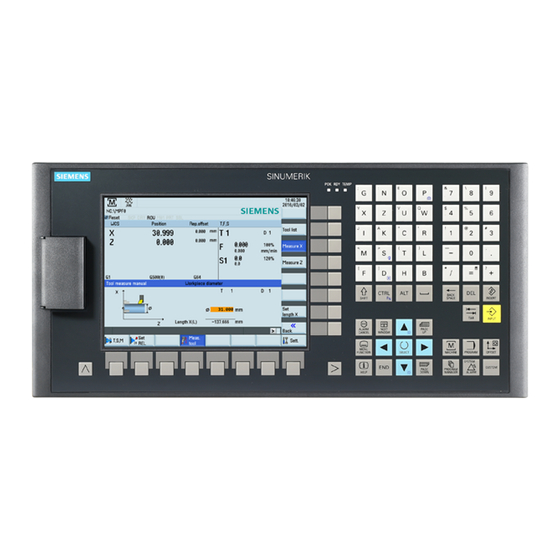
Introduction SINUMERIK 808D operator panels Elements on the PPU (Panel Processing Unit) front ① ⑦ Vertical and horizontal softkeys On-board assistant key Calls specific menu functions Provides step-by-step guides on basic commissioning and operation procedures ② ⑧ Return key Help key Returns to the next higher-level menu Calls help information ③... - Page 8 Introduction 1.1 SINUMERIK 808D operator panels Further information Control keys Deletes a character selected to the left of the cursor Deletes the selected file or character Indents the cursor by several characters Toggles between the input field and the selected program name ...
- Page 9 Introduction 1.1 SINUMERIK 808D operator panels Key combinations Key combination Description <ALT> + <X> Opens the machining operating area: <ALT> + <V> Opens the program editing operating area: <ALT> + <C> Opens the offset parameters operating area: <ALT> + <B> Opens the program management operating area: <ALT>...
-
Page 10: Machine Control Panels
Introduction 1.2 Machine control panels Machine control panels Elements on the MCP (Machine Control Panel) front ① ⑥ Emergency stop key User-defined keys * Stops all machine motions immediately (all with LED status indicators) ② ⑦ Handwheel key Axis traversing keys * (with LED status indicator) Controls the axis movement with external handwheels ③... - Page 11 Introduction 1.2 Machine control panels User-defined keys Pressing this in any operating mode switches on/off the lamp. LED lit: The lamp is switched on. LED unlit: The lamp is switched off. Pressing this key in any operating mode switches on/off the coolant supply.
- Page 12 Introduction 1.2 Machine control panels Resets NC programs Cancels alarms that meet the cancel criterion Pre-defined insertion strips The MCP (machine control panel) package includes two sets (six pieces each) of pre- defined insertion strips. One set is for the turning version of the control system and is pre- inserted in the back of the MCP.
-
Page 13: Coordinate Systems
Introduction 1.3 Coordinate systems 3. Detach the insertion strips from the blank plastic sheet. 4. Pull out the pre-inserted strips from the MCP. 5. Insert the customized strips on the back of the MCP. Note This manual assumes an 808D standard machine control panel (MCP). Should you use a different MCP, the operation may be other than described herein. - Page 14 Introduction 1.3 Coordinate systems The origin of this coordinate system is the machine zero. This point is only a reference point which is defined by the machine manufacturer. It does not have to be approachable. The traversing range of the machine axes can be in the negative range. Workpiece coordinate system (WCS) To describe the geometry of a workpiece in the workpiece program, a right-handed, right- angled coordinate system is also used.
- Page 15 Introduction 1.3 Coordinate systems Relative coordinate system (REL) In addition to the machine and workpiece coordinate systems, the control system provides a relative coordinate system. This coordinate system is used to set reference points that can be freely selected and have no influence on the active workpiece coordinate system. All axis movements are displayed relative to these references.
- Page 16 Introduction 1.3 Coordinate systems Current workpiece coordinate system The programmed work offset TRANS can be used to generate an offset with reference to the workpiece coordinate system, resulting in the current workpiece coordinate system. Milling Part 1: Operation Programming and Operating Manual, 12/2012, 6FC5398-4DP10-0BA0...
-
Page 17: Software Interface
Introduction 1.4 Software interface Software interface 1.4.1 Screen layout Status area Application area ① ⑧ Active operating area Actual value window ② ⑨ Active operating mode T, F, S window ③ ⑩ Alarm and message prompt area Operating window with program block display ④... - Page 18 Introduction 1.4 Software interface Status area Display Meaning ① Active operating Machining operating area area System data management operating area Program editing operating area Program management operating area Offset parameters operating area Diagnostics operating area ② Active operating "REF POINT" mode mode "JOG"...
- Page 19 Introduction 1.4 Software interface Display Meaning ③ Alarms and Displays active alarms with alarm text messages The alarm number is displayed in white lettering on a red background. The associated alarm text is shown in red lettering. An arrow indicates that several alarms are active. The number to the right of the arrow indicates the total number of active alarms.
-
Page 20: Protection Levels
SINUMERIK 808D provides a concept of protection levels for enabling data areas. Different protection levels control different access rights. The control system delivered from SIEMENS is set by default to the lowest protection level 7 (without password). If the password is no longer known, the control system must be reinitialized with the default machine data. - Page 21 Introduction 1.4 Software interface Protection level 1 Protection level 1 requires a manufacturer password. With this password entry, you can perform the following operations: ● Entering or changing all machine data ● Conducting NC commissioning Protection level 3-6 Protection level 3-6 requires an end-user password. With this password entry, you can perform the following operations: ●...
-
Page 22: The Help System
Alarms selected in the alarm specific operation area Machine data or setting data selected ② Calls the OEM-developed PDF manual ③ Displays all available help information: Siemens help manuals OEM-developed help manuals, if any Milling Part 1: Operation Programming and Operating Manual, 12/2012, 6FC5398-4DP10-0BA0... - Page 23 Introduction 1.4 Software interface Softkeys in Window "①" Use this softkey to select cross references A cross reference is marked by the characters "≫ ... ≪". Note: This softkey is displayed only if the current page contains a cross reference. Searches for a term in the current topic Continues search for the next term that matches the search criteria Exits the help system...
- Page 24 Introduction 1.4 Software interface Navigates upwards through the hierarchical topics Navigates downwards through the hierarchical topics Opens the selected topic in the current topic relevant window Functions the same as pressing the following key: Searches for a term in the current topic Continues search for the next term that matches the search criteria Exits the help system Milling...
-
Page 25: Turning On, Reference Point Approach
Turning on, reference point approach Note When turning on/off the CNC and the machine, also observe the machine tool manufacturer's documentation, since turning on and reference point approach are machine- dependent functions. Operating sequence Switch on the power supply for the control system and the machine. Release all emergency stop buttons on the machine. - Page 26 Turning on, reference point approach Milling Part 1: Operation Programming and Operating Manual, 12/2012, 6FC5398-4DP10-0BA0...
-
Page 27: Setting-Up
Setting-up Overview When working with the CNC, you need to set up the machine and the tools, etc. as follows: ● Create the tools and cutting edges. ● Enter/modify the tool and work offsets. ● Enter the setting data. Softkey functions Pressing this key on the PPU allows you to open the following window: ①... -
Page 28: Setting Up Tools
Setting-up 3.1 Setting up tools Setting up tools 3.1.1 Creating a new tool Operating sequence Select the desired operating area. Open the tool list window. Open the lower-level menu for tool type selection. Select a desired tool type with the corresponding softkey. Enter the tool number (value range: 1 to 31999;... -
Page 29: Creating A New Cutting Edge
Setting-up 3.1 Setting up tools 3.1.2 Creating a new cutting edge Operating sequence Select the desired operating area. Open the tool list window. Select the tool to which you desire to add a cutting edge. Open the lower-level menu for cutting edge settings. Press this softkey to create a new cutting edge for the selected tool. -
Page 30: Entering The Tool Offsets
Setting-up 3.1 Setting up tools 3.1.3 Entering the tool offsets The tool offsets consist of the data describing the geometry, the wear and the tool type. Each tool contains a defined number of cutting edge parameters dependent on the particular tool type. -
Page 31: Activating The Tool And Starting The Spindle
Setting-up 3.1 Setting up tools 3.1.4 Activating the tool and starting the spindle Operating sequence Select the desired operating area. Switch to "JOG" mode. Open the "T, S, M" window. Enter the desired values for the tool number , cutting edge number and spindle speed (for example, T1, D1 and 500 rpm) in the "T, S, M"... -
Page 32: Assigning The Handwheel
Setting-up 3.1 Setting up tools 3.1.5 Assigning the handwheel Operating sequence Select the desired operating area. Press this key on the MCP. Press the desired axis traversing key with the handwheel icon. The handwheel is assigned. Alternatively, you can assign the handwheels using the softkeys: Select the desired operating area. -
Page 33: Measuring The Tool (Manually)
Setting-up 3.1 Setting up tools Select the desired handwheel number with the cursor left/right key. 10. Press the relevant axis softkey for handwheel assignment or deselection. The symbol "☑" that appears in the window indicates a handwheel has been assigned to the specific axis. 11. - Page 34 Setting-up 3.1 Setting up tools Figure 3-1 Determination of the length offset using the example of a drill 1/Z axis length (milling) Operating sequence Select the desired operating area. Switch to "JOG" mode. Open the lower-level menu for tool measurement. Open the manual tool measurement window.
- Page 35 Setting-up 3.1 Setting up tools Select a suitable override feedrate, and then use the handwheel to move the tool to scratch the required workpiece edge. Press this key to set the reference point as required (for example, the workpiece). Enter the distance between the tool tip and the reference point in the "ZØ"...
-
Page 36: Measuring The Tool With A Probe (Auto)
Setting-up 3.1 Setting up tools 14. Enter the distance to the workpiece edge in the X and Y directions in the "X∅" and "Y∅" fields respectively. 15. Save the tool diameter value. Repeat the above operations for other tools and make sure you measure all the tools before machining, which also eases the tool changing process. - Page 37 Setting-up 3.1 Setting up tools Change the tool number T or cutting edge number D in the following window if necessary. Note: Only when you measure the tool without the tool carrier that can be oriented, it is necessary to change the cutting edge number. ...
-
Page 38: Calibrating The Tool Probe
Setting-up 3.1 Setting up tools 3.1.8 Calibrating the tool probe Overview To be able to measure your tools automatically, you must first determine the position of the tool probe based on the machine zero position. Operating sequences Setting the probe data Select the desired operating area. - Page 39 Setting-up 3.1 Setting up tools ④ ⑨ The diameter of the probe (the Direction of rotation of the spindle: M3, measured value will be shown after M4, or M5 calibrating) ⑤ The thickness of the probe ⑩ The minimum distance between the workpiece surface and the workpiece (this parameter is used to create the measuring program)
-
Page 40: Setting Up The Workpiece
Setting-up 3.2 Setting up the workpiece Setting up the workpiece 3.2.1 Entering / modifying work offsets Functionality After the machine approaches the reference point, the actual value of the axis coordinate is based on the machine zero (M) of the machine coordinate system. A machining program, however, is always based on the workpiece zero (W) of the workpiece coordinate system. -
Page 41: Measuring The Workpiece
Setting-up 3.2 Setting up the workpiece 3.2.2 Measuring the workpiece Overview You have selected the window with relevant work offset (e.g.G54) and the axis you want to determine for the offset. Figure 3-2 Determining the work offset (milling) Before measuring, you can start the spindle by following the steps in Section "Activating the tool and starting the spindle (Page 31)". - Page 42 Setting-up 3.2 Setting up the workpiece Traverse the tool, which has been measured previously, to approach the workpiece in the X direction. Switch to "HANDWHEEL" mode. Select a suitable override feedrate, and then use the handwheel to move the tool to scratch the required workpiece edge. Select the offset plane to save in and the measuring direction (for example, "G54"...
- Page 43 Setting-up 3.2 Setting up the workpiece Traverse the tool, which has been measured previously, in the direction of the orange arrow P1 shown in the measuring window, in order to scratch the workpiece edge with the tool tip. Press this vertical softkey to save the tool position P1 in the coordinate system.
-
Page 44: Entering / Modifying The Setting Data
Setting-up 3.3 Entering / modifying the setting data Entering / modifying the setting data Entering/modifying the setting data Operating sequence Select the desired operating area. Open the setting data window. Position the cursor bar in the input fields to be modified and enter the values (see table below for the parameter descriptions). - Page 45 Setting-up 3.3 Entering / modifying the setting data Min. (G25) fields can only be performed within the displayed as the start angle. A multiple thread can be cut ④ limit values defined in the machine data. by changing the angle when the thread cutting operation is repeated.
- Page 46 Setting-up 3.3 Entering / modifying the setting data ② ⑥ The number of workpieces required (workpiece Processing time in seconds setpoint) ③ ⑦ The number of all workpieces produced since the The time since the last control power up with default starting time values ("cold restart") in minutes ④...
-
Page 47: Setting The R Parameters
Setting-up 3.4 Setting the R parameters Setting the R parameters Operating sequence Select the desired operating area. Open the list of R parameters. Use the cursor keys to navigate in the list, and enter the values in the input fields to be modified. Note: You can search for your desired R variable with the following softkey. -
Page 48: Other Settings In "Jog" Mode
Setting-up 3.5 Other settings in "JOG" mode Other settings in "JOG" mode Softkey functions Pressing key on the PPU and then key on the MCP allows you to open the following window: ① ⑥ Opens the "T, S, M" window where you can activate Opens the settings window where you can set JOG tools, set spindle speed and direction, and select a G feedrate and variable increment values. -
Page 49: Setting The Relative Coordinate System (Rel)
Setting-up 3.5 Other settings in "JOG" mode Parameters in the "JOG" window ① ④ Displays the axes that exist in the machine coordinate Displays the currently active tool number T with the system (MCS), workpiece coordinate system (WCS), or current cutting edge number D. relative coordinate system (REL). -
Page 50: Face Milling
Setting-up 3.5 Other settings in "JOG" mode Use this key or move the cursor to confirm your entries. You can use the following vertical softkeys to set the reference point to zero: Set the X axis to zero Set the Y axis to zero Set the Z axis to zero Set the spindle to zero Set all axes to zero... - Page 51 Setting-up 3.5 Other settings in "JOG" mode Select the cutting path of the tool during machining. Use this softkey to confirm your settings. The system now automatically creates the part program. Press this key on the MCP to run the part program. Parameters for face milling ①...
-
Page 52: Setting The Jog Data
Setting-up 3.5 Other settings in "JOG" mode 3.5.3 Setting the JOG data Operating sequence Select the desired operating area. Switch to "JOG" mode. Press this horizontal softkey to open the following window: Enter values in the input fields and confirm your entries. If necessary, press this vertical softkey to switch between the metric and inch dimension systems. -
Page 53: Part Programming
Part programming Softkey functions Pressing this key on the PPU allows you to open the following window: ① Stores the NC programs for subsequent ⑨ Creates new files or directories operations ② ⑩ Manages and transfers OEM cycles Searches for files ③... -
Page 54: Creating Files Or Folders
Part programming 4.1 Creating files or folders Creating files or folders Creating a part program To create a part program, follow these steps: Select the desired operating area. Enter the folder for the new program to be created. Press this vertical softkey. Press this softkey to activate the window for creating a new program. -
Page 55: Editing Part Programs
Part programming 4.2 Editing part programs Editing part programs Overview A part program or sections of a part program can only be edited if currently not being executed. Operating sequence Select the desired operating area. Enter the program directory. Use this softkey or the cursor keys to select the program file to be edited. Press this key to open the program file. - Page 56 Part programming 4.2 Editing part programs Searching for strings Proceed through the following steps to search for strings: Press this softkey in the opened program editor window. Press this softkey to search via text. Alternatively, you can search with a given line number by pressing the following softkey: Enter the search text or line number in the input field, and press this key to select a starting point for search.
-
Page 57: Managing Part Programs
Part programming 4.3 Managing part programs Use the relevant keys on the NC keyboard to enter one or several blocks in the MDA window to create a new part program. Alternatively, press the following softkey to load an existing part program from a system directory and edit the blocks in the MDA window: After you finish editing, you can perform further operations as follows: Execute the program blocks displayed in the MDA window. - Page 58 Part programming 4.3 Managing part programs Use this key to choose whether to include subordinate folders or observe upper / lower case. Press this softkey to start the search, or otherwise, press the following softkey to cancel the search: Copying and pasting programs Select the desired operating area.
- Page 59 Part programming 4.3 Managing part programs Renaming programs Select the desired operating area. Choose the desired storage location and position the cursor on the file or directory which you would like to rename. Press the extension softkey to access more options. Press this vertical softkey to open the window for renaming.
-
Page 60: Calculating Contour Elements
Part programming 4.4 Calculating contour elements Calculating contour elements Function You can use the calculator to calculate the contour elements in the respective input screens. Calculating a point in a circle Activate the calculator when you are in any input screen. Open the lower-level menu for contour elements selection. - Page 61 Part programming 4.4 Calculating contour elements Example Example: Calculating the point of intersection between the circle sector ① and the straight line ② in plane G17. Figure 4-1 Example 1 Given: Radius: 10 Circle center point CC: Y=20 X=20 Connection angle for straight lines: 45° Result: Y = 27.071 X = 12.928 The result appears on the input screen.
- Page 62 Part programming 4.4 Calculating contour elements Calculating a point in a plane Activate the calculator when you are in any input screen. Open the lower-level menu for contour elements selection. Select the desired calculation function. Enter the following coordinates or angles in the respective input fields: ...
- Page 63 Part programming 4.4 Calculating contour elements Calculating the end point Activate the calculator when you are in any input screen. Open the lower-level menu for contour elements selection. Select the desired calculation function. This function calculates the missing end point of the straight line/straight line contour section whereby the second straight line stands vertically on the first straight line.
- Page 64 Part programming 4.4 Calculating contour elements Example The following drawing must be supplemented by the value of the center circle point in order to be able to calculate the point of intersection between the circle sector of the straight lines. Figure 4-2 Calculation of M1 The missing center point coordinate is calculated using the calculator function, as the radius...
-
Page 65: Free Contour Programming
Part programming 4.5 Free contour programming Free contour programming Functionality Free contour programming enables you to create simple and complex contours. A contour editor (FKE) calculates any missing parameters for you as soon as they can be obtained from other parameters. You can link together contour elements and transfer to the edited part program. -
Page 66: Programming A Contour
Part programming 4.5 Free contour programming ① ⑤ An element was selected using the cursor keys. This Press this softkey to toggle between the selections. softkey enlarges the image section of the selected This softkey functions the same as pressing the element. -
Page 67: Defining A Start Point
Part programming 4.5 Free contour programming Recompile When the program edited in the contour editor is opened in the program editor, if you position the editor cursor in a command line of the contour program and then press this softkey, the main screen of the contour editor opens and you can recompile the existing contour. -
Page 68: Programming Contour Element
Part programming 4.5 Free contour programming 4.5.3 Programming contour element Functionality Once you have defined the contour start point, press this softkey and you can begin programming the individual contour elements from the main screen shown below: ① Opens the window for programming a ⑤... - Page 69 Part programming 4.5 Free contour programming Display all parameters Press this softkey to display a selection list of all the parameters for the selected contour element. If you leave any parameter input fields blank, the control assumes that you do not know the right values and attempts to calculate these from the settings of the other parameters.
- Page 70 Part programming 4.5 Free contour programming Confirm your inputs with the following softkey: Select contour element Position the cursor on the desired contour element in the contour chain, and select it using this key. The parameters for the selected element will then be displayed. The name of the element appears at the top of the parameterization window.
-
Page 71: Parameters For Contour Elements
Part programming 4.5 Free contour programming Contour symbol colors The meaning of the symbol colors in the contour chain on the left of the main screen is as follows: Icon Significance Selected Symbol color black on a red background -> Element is defined geometrically Symbol color black on a light yellow background ->... - Page 72 Part programming 4.5 Free contour programming The following additional parameters are displayed after you press this softkey: Parameter Description Length of the straight line α1 Pitch angle with reference to Y axis Parameters for programming circular arcs ① Direction of rotation of the circular arc: ④...
- Page 73 Part programming 4.5 Free contour programming Transition to next element A transition element can be used whenever there is a point of intersection between two neighboring elements; this can be calculated from the input values. You can choose to insert either a radius (RND), a chamfer (CHR) or an undercut as the transition element between any two contour elements.
- Page 74 Part programming 4.5 Free contour programming A new contour element is inserted after the cursor when you select one of the contour elements on the vertical softkey bar; the input focus is then switched to the parameter input on the right of the graphic display. Programming always continues after the element selected in the contour chain.
-
Page 75: Specifying Contour Elements In Polar Coordinates
Part programming 4.5 Free contour programming 4.5.5 Specifying contour elements in polar coordinates Functionality The description about defining the coordinates of contour elements applies to the specification of positional data in the Cartesian coordinate system. Alternatively, you have the option to define positions using polar coordinates. When programming contours, you can define a pole at any time prior to using polar coordinates for the first time. - Page 76 Part programming 4.5 Free contour programming A toggle field is not displayed if no pole exists. Input fields and display fields are then only available for Cartesian values. Absolute/incremental input Absolute and incremental polar coordinates can be input for "polar/Cartesian". The input fields and display fields are labeled inc and abs.
- Page 77 Part programming 4.5 Free contour programming Pole change example Figure 4-4 pole change (milling) Pole: Xpole = 0.0, Ypole = 0.0, (Pole 0) End point: L1abs = 10.0 ϕabs = 30.0° Calculated Cart. Coordinates Xabs = 8.6603 Yabs = 5.0 New pole: Xpole1 = 5.0 Ypole1 = 5.0...
-
Page 78: Cycle Support
Part programming 4.5 Free contour programming 4.5.6 Cycle support Functionality The technologies below are provided with the additional support in the form of pre-defined cycles, which then must be parameterized. ● Drilling ● Milling For more information, refer to the Programming and Operating Manual (Milling) Part 2. 4.5.7 Programming example for milling Example 1... - Page 79 Part programming 4.5 Free contour programming Operating sequence: Select the desired operating area. Enter the desired program folder. Select a program with cursor keys and press this key to open the program in the program editor. Press this softkey to open the contour editor. Define a start point with the following parameters and press this softkey to confirm.
- Page 80 Part programming 4.5 Free contour programming 15. Enter the parameters for this element and press this softkey to select the desired contour characteristics. Direction of rotation: clockwise R: 72 X: 5.67 abs. Y: 0 abs. 16. Press this softkey to confirm. Now you can see the programmed contour in the graphics window: Milling Part 1: Operation...
- Page 81 Part programming 4.5 Free contour programming Example 2 Starting point: X=0 abs., Y=0 abs., machining plane G17 The contour is programmed in the clockwise direction with dialog selection. Figure 4-6 Workshop drawing of the contour, example 2 Operating sequence: Select the desired operating area. Enter the desired program folder.
- Page 82 Part programming 4.5 Free contour programming Press this softkey to select a contour element of straight vertical line. Enter the parameters for this element and press this softkey to confirm. Y: -104 abs. Press this softkey to select a contour element of circular arc. Enter the parameters for this element and press this softkey to select the desired contour characteristics.
- Page 83 Part programming 4.5 Free contour programming 19. Press this softkey to select a contour element of circular arc. 20. Enter the parameters for this element and press this softkey to select the desired contour characteristics. Direction of rotation: clockwise ...
- Page 84 Part programming 4.5 Free contour programming Example 3 Starting point: X=0 abs., Y=5.7 abs., machining plane G17 The contour is programmed in a clockwise direction. Figure 4-7 Workshop drawing of the contour, example 3 Operating sequence: Select the desired operating area. Enter the desired program folder.
- Page 85 Part programming 4.5 Free contour programming Press this softkey to select a contour element of circular arc. Enter the parameters for this element and press this softkey to select the desired contour characteristics. Direction of rotation: counter-clockwise R: 9.5 ...
- Page 86 Part programming 4.5 Free contour programming 19. Press this softkey to confirm. 20. Press this softkey to select a contour element of straight line in any direction. 21. Enter the parameters for this element and press this softkey to select the desired contour characteristics.
-
Page 87: Automatic Machining
Automatic machining Overview The machine must have been set up for "AUTO" mode according to the specifications of the machine manufacturer. You can perform such operations as program start, stop, control, block search, and real-time simulation, etc. Softkey functions Pressing key on the PPU and then key on the MCP allows you to open the following window:... -
Page 88: Performing The Simulation
Automatic machining 5.1 Performing the simulation Parameters ① ③ Displays the axes that exist in the machine coordinate Displays the remaining distance for the axes to system (MCS), workpiece coordinate system (WCS), or traverse. relative coordinate system (REL). ② ④ Displays the current position of the axes in the selected Displays seven subsequent blocks of the currently coordinate system. - Page 89 Automatic machining 5.1 Performing the simulation Press this softkey to open the program simulation window, and the program control mode PRT is automatically activated. If the control system is not in the correct operating mode, a message appears at the bottom of the screen as follows. If this message appears, repeat Step 4.
-
Page 90: Program Control
Automatic machining 5.2 Program control Program control Operating sequence Select the desired operating area. Switch to "AUTO" mode. Press this softkey to open the lower-level menu for program control. Press the corresponding vertical softkey to activate or deactivate the desired program control option (see table below for detailed softkey functions). -
Page 91: Program Test
Automatic machining 5.3 Program test The feedrate override switch also acts on the rapid traverse override. It functions the same as pressing the following key: Note: After pressing the above softkeys or keys, the corresponding icons appear immediately in the program status bar and the selected softkeys are highlighted in blue. -
Page 92: Starting And Stopping / Interrupting A Part Program
Automatic machining 5.4 Starting and stopping / interrupting a part program Starting and stopping / interrupting a part program Starting a part program Before starting a program, make sure that both the control system and the machine are set up. Observe the relevant safety notes of the machine manufacturer. Operating sequence Select the desired operating area. -
Page 93: Executing / Reading In A Part Program From External
Automatic machining 5.5 Executing / reading in a part program from external Executing / reading in a part program from external Communication tool - SinuComPCIN To enable the RS232 communication between a SINUMERIK 808D and a PC/PG, you must have the RS32 communication tool SinuComPCIN installed on your PC/PG. This tool is available in the SINUMERIK 808D Toolbox. - Page 94 Automatic machining 5.5 Executing / reading in a part program from external Executing a part program from external Proceed as follows to execute a part program from external via the RS232 interface: Select the desired operating area on the PPU. Press this softkey to go to the RS232 directory.
- Page 95 Automatic machining 5.5 Executing / reading in a part program from external Reading in a part program from external Note The program files can be transferred only to the system drive N:\MPF or N:\CMA; therefore, before transfer, make sure the drive identifier contained in the first line in the program file is "N"...
-
Page 96: Machining At A Specific Point
Automatic machining 5.6 Machining at a specific point Machining at a specific point Functionality The block search function provides advance of the program to the required block in the part program. You can start machining from a specified program block after stopping / interrupting the program execution or during remachining. - Page 97 Automatic machining 5.6 Machining at a specific point Press this key on the MCP, and then an alarm 010208 appears for your confirmation whether to continue. Press this key again to execute the program. Turn the feedrate override switch on the MCP slowly to the desired value. Milling Part 1: Operation Programming and Operating Manual, 12/2012, 6FC5398-4DP10-0BA0...
- Page 98 Automatic machining 5.6 Machining at a specific point Milling Part 1: Operation Programming and Operating Manual, 12/2012, 6FC5398-4DP10-0BA0...
-
Page 99: System
System Softkey functions Pressing the above key combination allows you to open the following window. This operating area includes functions required for parameterizing and analyzing the NCK, the PLC and the drive. ① ⑧ Sets the NC, PLC and HMI start up modes Creates and restores startup archives, data archive ②... - Page 100 System Saving data This function saves the NC and PLC data of the volatile memory into a non-volatile memory area. Requirement: There is no program currently executing. Proceed through the following steps to save data: Select the desired operating area. Open the window for data saving.
-
Page 101: Data Backup
Data backup Copying and pasting files In the program management operating area, program files or directories can be copied into another directory or onto a different drive by means of copying and pasting operations. Operating sequence Select the desired operating area. Enter the program directory. - Page 102 Data backup Backing up files via RS232 interface The program files can be backed up onto an external PC/PG via the RS232 interface. Operating sequence Connect the control system with the PC/PG using an RS232 cable. Configure the communication settings for the RS232 interface (see Section "Executing / reading in a part program from external (Page 93)").
-
Page 103: Appendix
Appendix Pocket calculator The calculator function can be activated from any other operating area using this key on the PPU (except in "MDA" mode). For calculating, the four basic arithmetic operations are available, as well as the functions "sine", "cosine", "squaring" and "square root". A bracket function is provided to calculate nested terms. - Page 104 Appendix A.1 Pocket calculator Characters that may be entered +, -, *, / Basic arithmetic operations Sine function The X value (in degrees) in front of the input cursor is replaced by the sin(X) value. Cosine function The X value (in degrees) in front of the input cursor is replaced by the cos(X) value.
-
Page 105: Editing Chinese Characters
Appendix A.2 Editing Chinese characters Editing Chinese characters The program editor and PLC alarm text editor both allow you to edit the simplified Chinese characters on the Chinese variant of the HMI. Editing simplified Chinese characters Press the key and key to switch the editor on or off. - Page 106 Appendix A.2 Editing Chinese characters Milling Part 1: Operation Programming and Operating Manual, 12/2012, 6FC5398-4DP10-0BA0...
-
Page 107: Index
Index Absolute/incremental, 76 Radius, 73 Arithmetic parameters, 47 Recompile, 67 RND, 73 Cartesian/polar, 75 Chamfer, 73 SINUMERIK 808D documentation set, 4 CHR, 73 Starting point, 73 Contour allowance, 71 Contour elements, 68 Contour transition element, 73 Coordinate systems Tangent to preceding element, 68 Machine coordinate system (MCS), 13 Tool zero, 40 Relative coordinate system, 15... - Page 108 Index Milling Part 1: Operation Programming and Operating Manual, 12/2012, 6FC5398-4DP10-0BA0...
Need help?
Do you have a question about the SINUMERIK 808D Milling and is the answer not in the manual?
Questions and answers