Siemens SINUMERIK 808D ADVANCED Programming And Operating Manual
Operator-panel-based cncs
Hide thumbs
Also See for SINUMERIK 808D ADVANCED:
- Diagnostic manual (566 pages) ,
- Parameter manual (524 pages) ,
- Commissioning manual (508 pages)
Table of Contents
Advertisement
Quick Links
SINUMERIK
SINUMERIK 808D ADVANCED
Programming and Operating Manual (Milling)
User Manual
Legal information
Warning notice system
This manual contains notices you have to observe in order to ensure your personal safety, as well as to prevent damage to property. The
notices referring to your personal safety are highlighted in the manual by a safety alert symbol, notices referring only to property damage
have no safety alert symbol. These notices shown below are graded according to the degree of danger.
DANGER
indicates that death or severe personal injury will result if proper precautions are not taken.
WARNING
indicates that death or severe personal injury may result if proper precautions are not taken.
CAUTION
indicates that minor personal injury can result if proper precautions are not taken.
NOTICE
indicates that property damage can result if proper precautions are not taken.
If more than one degree of danger is present, the warning notice representing the highest degree of danger will be used. A notice warning of
injury to persons with a safety alert symbol may also include a warning relating to property damage.
Qualified Personnel
The product/system described in this documentation may be operated only by personnel qualified for the specific task in accordance with
the relevant documentation, in particular its warning notices and safety instructions. Qualified personnel are those who, based on their
training and experience, are capable of identifying risks and avoiding potential hazards when working with these products/systems.
Proper use of Siemens products
Note the following:
WARNING
Siemens products may only be used for the applications described in the catalog and in the relevant technical documentation. If products
and components from other manufacturers are used, these must be recommended or approved by Siemens. Proper transport, storage,
installation, assembly, commissioning, operation and maintenance are required to ensure that the products operate safely and without any
problems. The permissible ambient conditions must be complied with. The information in the relevant documentation must be observed.
© Siemens AG 2014. All rights reserved
6FC5398-4DP10-0BA1, 01/2014
1
Advertisement
Table of Contents

Related Manuals for Siemens SINUMERIK 808D ADVANCED


Summary of Contents for Siemens SINUMERIK 808D ADVANCED
- Page 1 WARNING Siemens products may only be used for the applications described in the catalog and in the relevant technical documentation. If products and components from other manufacturers are used, these must be recommended or approved by Siemens. Proper transport, storage, installation, assembly, commissioning, operation and maintenance are required to ensure that the products operate safely and without any problems.
-
Page 2: Preface
Mechanical and electrical designers, technical professionals, and commissioning engineers My Documentation Manager (MDM) Under the following link you will find information to individually compile your documentation based on the Siemens content: www.siemens.com/mdm Standard scope This manual only describes the functionality of the standard version. Extensions or changes made by the machine tool manufacturer are documented by the machine tool manufacturer. -
Page 3: Table Of Contents
Table of contents Preface ................................... 2 Introduction................................7 SINUMERIK 808D ADVANCED operator panels ..................7 1.1.1 Overview ............................... 7 1.1.2 Control elements on the PPU ........................8 Machine control panels ..........................10 1.2.1 Overview ..............................10 1.2.2 Control elements on the MCP ........................11 Screen layout .............................. - Page 4 8.2.1 Programming dimensions ........................... 51 8.2.2 Plane selection: G17 to G19 ........................51 8.2.3 Absolute/incremental dimensioning: G90, G91, AC, IC ................52 8.2.4 Dimensions in metric units and inches: G71, G70, G710, G700 ..............53 8.2.5 Polar coordinates, pole definition: G110, G111, G112................54 8.2.6 Programmable work offset: TRANS, ATRANS ...................
- Page 5 8.14.4 Jump destination for program jumps ......................110 8.15 Subroutine technique ..........................110 8.15.1 General information........................... 110 8.15.2 Calling machining cycles ........................... 112 8.15.3 Modal subroutine call ..........................113 8.15.4 Execute external subroutine (EXTCALL) ....................113 8.16 Timers and workpiece counters ........................ 114 8.16.1 Runtime timer ............................
- Page 6 Entering/modifying the setting data......................222 Setting R parameters ..........................225 Setting user data............................225 Other settings in "JOG" mode ........................226 A.8.1 Setting the relative coordinate system (REL) .................... 227 A.8.2 Face milling .............................. 228 A.8.3 Setting the JOG data ..........................229 The help system ............................
-
Page 7: Introduction
SINUMERIK 808D ADVANCED T (turning) or SINUMERIK 808D ADVANCED M (milling) control system ● PPU160.2 vertical panel layout, applicable for the SINUMERIK 808D ADVANCED T (turning) or SINUMERIK 808D ADVANCED M (milling) control system PPU161.2 (horizontal panel layout) PPU160.2 (vertical panel layout) -
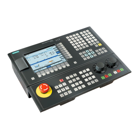
Page 8: Control Elements On The Ppu
1.1.2 Control elements on the PPU Elements on the PPU (Panel Processing Unit) front The following illustration uses PPU161.2 as an example to show control elements available on the PPU: ① Vertical and horizontal softkeys ⑦ On-board wizard key Calls specific menu functions Provides step-by-step guides on basic commissioning and operation procedures ②... - Page 9 Enables user-defined extension applications, for example, generation of user dialogs with the EasyXLanguage function. For more information about this function, refer to SINUMERIK 808D ADVANCED Function Manual. Status LEDs LED "POK" Lights up green: The power supply for the CNC is switched on.
-
Page 10: Machine Control Panels
Machine control panels 1.2.1 Overview Elements on the MCP (Machine Control Panel) front The SINUMERIK 808D MCP is available in the following variants: ● Horizontal MCP variant ● Vertical MCP variant with a reserved slot for the handwheel ● Vertical MCP variant with an override switch for the spindle Horizontal MCP Vertical MCP with reserved handwheel slot Vertical MCP with spindle override switch... -
Page 11: Control Elements On The Mcp
1.2.2 Control elements on the MCP Elements on the MCP (Machine Control Panel) front The following illustration uses a horizontal MCP as an example to show control elements available on the MCP: ① Reserved hole for emergency stop button ⑦ Axis traversing keys ②... - Page 12 MCP. The other set is for the milling variant of the control system. If your control system is of the SINUMERIK 808D ADVANCED milling variant, replace the pre-inserted strips with the milling- specific insertion strips.
-
Page 13: Screen Layout
In the \examples\MCP folder of the Toolbox DVD for the SINUMERIK 808D ADVANCED, there is a symbol library file and an insertion strip template file. To make customized insertion strips, follow the steps below: 1. -
Page 14: Protection Levels
The control system delivered by SIEMENS is set by default to the lowest protection level 7 (without password). If the password is no longer known, the control system must be reinitialized with the default machine/drive data. All passwords are then reset to default passwords for this software release. -
Page 15: Setting User Interface Language
Setting user interface language Operating sequence Select the desired operating area. Press this softkey to open the user interface language selection window. Use the cursor keys to select the desired language. Press this softkey to confirm your selection. Note: The HMI (Human Machine Interface) is automatically restarted when a new language is selected. -
Page 16: Setting-Up
Press the corresponding axis traversing keys to traverse each axis to the reference point. If an axis is referenced, a symbol ( ) is shown next to the axis identifier and is visible only in the ""REF POINT" window. Note that axis traversing directions and axis key functions are defined by the machine manufacturer. - Page 17 Machine coordinate system (MCS) The orientation of the coordinate system relative to the machine depends on the respective machine types. It can be rotated in different positions. The directions of the axes follow the "3-finger rule" of the right hand. Seen from the front of the machine, the middle finger of the right hand points in the opposite direction to the infeed of the spindle.
- Page 18 Relative coordinate system (REL) In addition to the machine and workpiece coordinate systems, the control system provides a relative coordinate system. This coordinate system is used to set reference points that can be freely selected and have no influence on the active workpiece coordinate system.
-
Page 19: Setting Up Tools
Setting up tools 3.2.1 Creating a new tool Note The control system supports a maximum of 64 tools or 128 cutting edges. Operating sequence Select the desired operating area. Open the tool list window. Open the lower-level menu for tool type selection. Select a desired tool type with the corresponding softkey. -
Page 20: Activating The Tool
Enter the tool radius data and confirm your settings. 3.2.2 Activating the tool Operating sequence Select the desired operating area. Switch to "JOG" mode. Open the "T, S, M" window. Enter the desired tool number (for example, 1) in the "T, S, M" window. Use this key or move the cursor to confirm your entries. - Page 21 Method 2: Assigning through the PPU Select the desired operating area. Open the machine data window. Press this softkey to open the basic machine data list. Use the cursor keys or the following softkey to search for the general machine data "14512 USER_DATA_HEX[16]".
-
Page 22: Activating The Spindle
Select the required override increment. The selected axis can now be moved with the handwheel. The override increment is 0.001 mm. The override increment is 0.010 mm. The override increment is 0.100 mm. 3.2.4 Activating the spindle Operating sequence Select the desired operating area. Switch to "JOG"... -
Page 23: Measuring The Tool (Manually)
3.2.5 Measuring the tool (manually) Overview Note For milling tools, both length and the radius must be determined; for drilling tools (see the following figure), only length must be determined. You can determine the tool length and radius and diameter by either measuring the tool or entering the values in the tool list (see Section "Creating a new tool (Page 19)"... - Page 24 Select a suitable override feedrate, and then use the handwheel to move the tool to scratch the required workpiece edge (or the edge of the setting block, if it is used). Press this key to set the reference point as required (for example, the workpiece). Enter the distance between the tool tip and the reference point in the "Z0"...
-
Page 25: Setting Up The Workpiece
Save the tool diameter value. Press this softkey and you can see that the compensation data values have been automatically added to the tool data. Repeat the above operations for other tools and make sure you measure all the tools before machining, which also eases the tool changing process. - Page 26 Traverse the tool, which has been measured previously, to approach the workpiece in the X direction. Switch to handwheel control mode. Select a suitable override feedrate, and then use the handwheel to move the tool to scratch the required workpiece edge. Select the offset plane to save in and the measuring direction (for example, "G54"...
- Page 27 Traverse the tool, which has been measured previously, in the direction of the orange arrow P1 shown in the measuring window, in order to scratch the workpiece edge with the tool tip. Press this vertical softkey to save the tool position P1 in the coordinate system. Repeat Steps 5 and 6 to save the other three positions: P2, P3 and P4.
-
Page 28: Verifying The Tool Offset Result In "Mda" Mode
3.2.7 Verifying the tool offset result in "MDA" mode In order to ensure the machine safety and correctness, you must test the results of the tool offset appropriately. Operating sequence Select the desired operating area. Switch to "MDA" mode. Press this softkey on the PPU. Enter the test program, for example: G54 T1 D1 G00 X0 Y0 Z5. -
Page 29: Entering/Modifying The Tool Wear Data
3.2.8 Entering/modifying the tool wear data Note You must distinguish the direction of tool wear compensation clearly. Operating sequence Select the desired operating area. Open the tool wear window. Use the cursor keys to select the required tools and their edges. Enter the tool length wear parameter and the tool radius wear parameter. -
Page 30: Operating Area Overview
Operating area overview When working with the CNC, you need to set up the machine and the tools, etc. as follows: ● Create the tools and cutting edges. ● Enter/modify the tool and work offsets. ● Enter the setting data. Softkey functions Pressing this key on the PPU allows you to open the following window: ①... -
Page 31: Part Programming
Part programming The SINUMERIK 808D ADVANCED control system can store a maximum of 300 part programs which include those created by the control system for certain functions such as MM+, TSM, and so on. Softkey functions Pressing this key on the PPU allows you to open the following window: ①... -
Page 32: Creating A Part Program
Creating a part program Operating sequence Select the desired operating area. Enter the folder for the new program to be created. If you desire to directly create a new program file, press this softkey and proceed to Step 4. Note: If you desire to create a new program directory first, press this softkey and proceed as follows before you go to Step 4: ①... -
Page 33: Editing Part Programs
Editing part programs Overview A part program or sections of a part program can only be edited if currently not being executed. Any modifications to the part program are stored immediately. Operating sequence Select the desired operating area. Enter the program directory. Select the program file you desire to edit. - Page 34 Searching for blocks Proceed through the following steps to search for a block: Press this softkey in the opened program editor window. Press this softkey to search via text. Alternatively, you can search with a given line number by pressing the following softkey: Enter the search text or line number in the input field.
-
Page 35: Managing Part Programs
Managing part programs Searching for programs Select the desired operating area. Select the storage medium in which you wish to perform the search. Note: The following two folders are visible with the manufacturer password: Press this vertical softkey to open the search window. Enter the complete name with extension of the program file to be searched in the first input field in the search window. - Page 36 Deleting / restoring programs Select the desired operating area. Open the desired directory. Select the program file that you would like to delete. Press this key, and the following message appears on the screen: Press this softkey to confirm the deletion, or press the following softkey to cancel: If you want to restore the last deleted file, press the following softkey: Renaming programs Select the desired operating area.
-
Page 37: Automatic Machining
Select the program file that you would like to execute. Press this vertical softkey to start executing the selected program. To clear the current file list, press the following softkey: Automatic machining Overview The machine must have been set up for "AUTO" mode according to the specifications of the machine manufacturer. You can perform such operations as program start, stop, control, block search, and real-time simulation, etc. -
Page 38: Performing The Simulation
Parameters ① ③ Displays the axes that exist in the machine coordinate Displays the remaining distance for the axes to system (MCS), workpiece coordinate system (WCS), or traverse. relative coordinate system(REL). ② ④ Displays the current position of the axes in the selected Displays seven subsequent blocks of the currently coordinate system. -
Page 39: Program Control
Press this key to start the standard simulation for the execution of the selected part program. Please note that the simulation function can be executed only when the control system is in the "AUTO" operating mode! Softkey functions The following describes the functions of the softkeys on the simulation main screen. ①... - Page 40 Softkey functions Disables the output of setpoints to axes and spindles. The setpoint display "simulates" the traverse movements. It functions the same as pressing the following key: After activating this option, the icon "PRT" appears immediately in the program status bar and this softkey is highlighted in blue.
-
Page 41: Program Test
Program test You can test a part program using three different methods before machining pieces. Testing the program with dry run With dry run, all programmed motion commands are replaced by a defined dry run feedrate (refer to Section "Entering/modifying the setting data (Page 222)"). Before executing the dry run, first remove the workpiece from the machine. -
Page 42: Starting And Stopping / Interrupting A Part Program
Testing the program with AFL The AFL (auxiliary function lock) function disables the spindle and suppresses all auxiliary functions. Auxiliary function Address Tool selection Tool offset D, DL Feedrate Spindle speed M functions H functions When the AFL is active, you can test the part program by checking the axis movement. Only one of the functions PRT and AFL can be active at the same time. -
Page 43: Executing / Transferring A Part Program Through The Rs232 Interface
Configuring RS232 communication Communication tool - SinuComPCIN To enable the RS232 communication between a SINUMERIK 808D ADVANCED and a PC/PG, you must have the RS232 communication tool SinuComPCIN installed on your PC/PG. This tool is available in the SINUMERIK 808D ADVANCED Toolbox. -
Page 44: Executing From External (Through Rs232 Interface)
Press this softkey to save your settings. If desired, you can press the following softkey to reset the settings to defaults: Return to the RS232 main screen. Open the SinuComPCIN on your PC/PG. Press this button on the main screen and then select the desired baudrate from the list. Note that this baudrate must be the same as that you have selected on the NC side. -
Page 45: Transferring From External (Through Rs232 Interface)
Note When using the external execution via RS232, the RS232 interface must not be active for another application. This means, for example, the RS232 interface must not be active through the following operation: > "PLC" > 5.5.3 Transferring from external (through RS232 interface) Prerequisites: ●... -
Page 46: Machining At A Specific Point
Machining at a specific point Functionality The block search function provides advance of the program to the required block in the part program. You can start machining from a specified program block after stopping / interrupting the program execution or during remachining. Operating sequence Select the desired operating area. -
Page 47: Saving System Data
Saving system data Saving data This function saves the NC and PLC data of the volatile memory into a non-volatile memory area. Prerequisite: ● A valid system password has been set on the control system. ● There is no program currently executing. Proceed through the following steps to save data: Select the desired operating area. - Page 48 An extended horizontal softkey bar can be accessed via this key on the PPU. Two extended horizontal softkeys are provided: Views the service information Defines the maintenance planner For more information about the softkey functions in this operating area, refer to SINUMERIK 808D ADVANCED Diagnostics Manual. Programming and Operating Manual (Milling) 6FC5398-4DP10-0BA1, 01/2014...
-
Page 49: Data Backup
Data backup Backing up files by copying and pasting In the program management operating area, program files or directories can be copied into another directory or onto a different drive by means of copying and pasting operations. Operating sequence Select the desired operating area. Enter the program directory. -
Page 50: Programming Principles
Enter the RS232 directory. Press this vertical softkey in the RS232 window. The file transferring starts. Wait until SinuComPCIN has finished data transfer, and click this button. For more information, refer to SINUMERIK 808D ADVANCED Diagnostics Manual. Programming principles Fundamentals of programming 8.1.1... -
Page 51: Positional Data
Positional data 8.2.1 Programming dimensions In this section you will find descriptions of the commands, with which you can directly program dimensions taken from a drawing. This has the advantage that no extensive calculations have to be made for NC programming. Note The commands described in this section stand in most cases at the start of a NC program. -
Page 52: Absolute/Incremental Dimensioning: G90, G91, Ac, Ic
The following plane and axis assignments are possible: G function Plane (abscissa/ordinate) Vertical axis on plane (length compensation axis when drilling/milling) See the following illustration for planes and axes when drilling/milling: Programming example N10 G17 T... D... M... ; X/Y plane selected N20 ... -
Page 53: Dimensions In Metric Units And Inches: G71, G70, G710, G700
See the following illustration for different dimensioning types in the drawing: Absolute dimensioning G90 With absolute dimensioning, the dimensioning data refers to the zero of the coordinate system currently active (workpiece or current workpiece coordinate system or machine coordinate system). This is dependent on which offsets are currently active: programmable, settable, or no offsets. -
Page 54: Polar Coordinates, Pole Definition: G110, G111, G112
Programming example N10 G70 X10 Z30 ; Inch dimensions N20 X40 Z50 ;G70 continues to act N80 G71 X19 Z17.3 ; metric dimensioning from this point on Information Depending on the default setting you have selected, the control system interprets all geometric values as either metric or inch dimensions. - Page 55 See the following illustration for polar radius and polar angle with definition of the positive direction in different planes: Pole definition, programming G110 Pole specification relative to the setpoint position last programmed (in the plane, e.g. with G17: X/Y) G111 ;...
-
Page 56: Programmable Work Offset: Trans, Atrans
8.2.6 Programmable work offset: TRANS, ATRANS Functionality The programmable work offset can be used: ● for recurring shapes/arrangements in various positions on the workpiece ● when selecting a new reference point for the dimensioning ● as a stock allowance when roughing This results in the current workpiece coordinate system. - Page 57 The instructions which contain ROT or AROT each require a separate block. See the following illustration for definition of the positive direction of the angle of rotation in the individual planes: See the following illustration for programming example for programmable offset and rotation: Programming example N10 G17 ...
-
Page 58: Programmable Scaling Factor: Scale, Ascale
8.2.8 Programmable scaling factor: SCALE, ASCALE Functionality A scale factor can be programmed for all axes with SCALE/ASCALE. The path is enlarged or reduced by this factor in the axis specified. The currently set coordinate system is used as the reference for the scale change. Programming SCALE X... - Page 59 Programming MIRROR X0 Y0 Z0 ; Programmable mirroring, clears old instructions for offset, rotation, scaling factor, mirroring AMIRROR X0 Y0 Z0 ; Programmable mirroring, additive to existing instructions MIRROR ; Without values: clears old instructions for offset, rotation, scaling factor, mirroring The instructions that contain MIRROR or AMIRROR each require a separate block.
-
Page 60: Workpiece Clamping - Settable Work Offset: G54 To G59, G500, G53, G153
8.2.10 Workpiece clamping - settable work offset: G54 to G59, G500, G53, G153 Functionality The settable work offset specifies the position of the workpiece zero on the machine (offset of the workpiece zero with respect to the machine zero). This offset is determined upon clamping of the workpiece into the machine and must be entered in the corresponding data field by the operator. -
Page 61: Nc Block Compression (Compon, Compcurv, Compcad)
Programming example N10 G54 ; Call first settable work offset N20 L47 ; Machining of workpiece 1, here using L47 N30 G55 ; Call second settable work offset N40 L47 ; Machining of workpiece 2, here using L47 N50 G56 ;... - Page 62 Supplementary conditions ● The NC block compression is generally executed for linear blocks (G1). ● Only blocks that comply with a simple syntax are compressed: N... G1X... Y... Z... F... ;comment All other blocks are executed unchanged (no compression). ● Motion blocks with extended addresses such as C=100 or A=AC(100) are also condensed. ●...
-
Page 63: Cylinder Surface Transformation (Tracyl)
8.2.12 Cylinder surface transformation (TRACYL) Functionality ● The TRACYL cylinder surface transformation function can be used to machine: – Longitudinal grooves on cylindrical bodies – Transverse grooves on cylindrical objects – Grooves with any path on cylindrical bodies The path of the grooves is programmed with reference to the unwrapped, level surface of the cylinder. ●... - Page 64 Rotary axis The rotary axis cannot be programmed as it is occupied by a geometry axis and thus cannot be programmed directly as channel axis. Meaning TRACYL(d) Activates the first TRACYL function specified in the channel machine data. d is the parameter for the working diameter. TRACYL (d, n) Activates the n-th TRACYL function specified in the channel machine data.
- Page 65 Example: Tool definition The following example is suitable for testing the parameterization of the TRACYL cylinder transformation: Program code Comment Tool parameters Meaning Number (DP) $TC_DP1[1,1]=120 Tool type (Milling tool) $TC_DP2[1,1]=0 Cutting edge position (Only for turning tools) Program code Comment Geometry Length compensation...
- Page 66 Activate cylinder surface transformation: Required tool: T1 milling tool, radius=3 mm, edge position=8 Program code Comment N10 T1 D1 G54 G90 G94 ; Tool selection, clamping compensation F1000 N20 SPOS=0 ; Approach the starting position N30 SETMS(2) ; Set the second spindle as the main spindle N40 M3 S2000 ;...
- Page 67 ● The second linear axis should not be used for traversing the part program. Certain machine data settings are assumed for the part program and the assignment of the corresponding axes in the BCS or MCS. For more information, refer to SINUMERIK 808D ADVANCED Function Manual. Programming and Operating Manual (Milling) 6FC5398-4DP10-0BA1, 01/2014...
- Page 68 Offset contour normal OFFN (transformation type 513) To mill grooves with TRACYL, the following is programmed: ● Groove center line in the part program ● Half the groove width programmed using OFFN. To avoid damage to the groove side OFFN acts only when the tool radius compensation is active. Furthermore, OFFN should also be >= the tool radius to avoid damage occurring to the opposite side of the groove.
-
Page 69: Linear Interpolation
● Guiding grooves: TRACYL does not create the same groove for guiding grooves as it would be with a tool with the diameter producing the width of the groove. It is basically not possible to create the same groove side geometry with a smaller cylindrical tool as it is with a larger one. -
Page 70: Feedrate F
Information Another group of G functions exists for movement to the position (see Section "Exact stop/continuous-path control mode: G9, G60, G64 (Page 84)"). For G60 exact stop, a window with various precision values can be selected with another G group. For exact stop, an alternative instruction with non-modal effectiveness exists: G9. - Page 71 Programming G1 X... Y... Z... F... ; Cartesian coordinates G1 AP=... RP=... F... ; Polar coordinates G1 AP=... RP=... Z... F... ; cylindrical coordinates (3dimensional) Note Another option for linear programming is available with the angle specification ANG=... (see Section "Contour definition programming (Page 88)").
-
Page 72: Circular Interpolation
Circular interpolation 8.4.1 Circular interpolation: G2, G3 Functionality The tool moves from the starting point to the end point along a circular path. The direction is determined by the G function: G2: clockwise G3: counter-clockwise The description of the desired circle can be given in various ways: See the following illustration for possibilities of circle programming with G2/G3 using the example of the axes X/Y and G2: G2/G3 remains active until canceled by another instruction from this G group (G0, G1, ...). - Page 73 Note Further possibilities for circle programming result from: CT - circle with tangential connection and CIP - circle via intermediate point (see next sections). Input tolerances for the circle Circles are only accepted by the control system with a certain dimensional tolerance. The circle radius at the starting and end points are compared here.
- Page 74 Programming example: Definition of center point and end point N5 G90 X30 Y40 ; Starting point circle for N10 N10 G2 X50 Y40 I10 J-7 ; End point and center point Note Center point values refer to the circle starting point! Programming example: End point and radius specification N5 G90 X30 Y40 ;...
- Page 75 Programming example: Definition of end point and aperture angle N5 G90 X30 Y40 ; Starting point circle for N10 N10 G2 X50 Y40 AR=105 ; End point and aperture angle Programming example: Definition of center point and aperture angle N5 G90 X30 Y40 ;...
-
Page 76: Circular Interpolation Via Intermediate Point: Cip
Programming example: Polar coordinates N1 G17 ; X/Y plane N5 G90 G0 X30 Y40 ; Starting point circle for N10 N10 G111 X40 Y33 ; Pole = circle center N20 G2 RP=12.207 AP=21 ; Polar specifications 8.4.2 Circular interpolation via intermediate point: CIP Functionality If you know three contour points of the circle, instead of center point or radius or aperture angle, then it is advantageous to use the CIP function. -
Page 77: Circle With Tangential Transition: Ct
See the following illustration for circle with end point and intermediate point specification using the example of G90: Programming example N5 G90 X30 Y40 ;Starting point circle for N10 N10 CIP X50 Y40 I1=40 J1=45 ; End point and intermediate point 8.4.3 Circle with tangential transition: CT Functionality... -
Page 78: Helix Interpolation: G2/G3, Turn
8.4.4 Helix interpolation: G2/G3, TURN Functionality With helix interpolation, two movements are overlaid: ● Circular movement in the G17, G18 or G19 plane ● Linear movement of the axis standing vertically on this plane. The number of additional full-circle passes is programmed with TURN=. These are added to the actual circle programming. -
Page 79: Thread Cutting
If you wish the programmed feedrate always to act at the cutter center point path, then disable the feedrate override. The modally acting G group that contains CFTCP/CFC (G functions) is provided for switching. Programming CFTCP ; Feedrate override OFF (the programmed feedrate acts at the milling cutter center point) ;... -
Page 80: Tapping With Compensating Chuck: G63
The drilling depth is specified by specifying one of the axes X, Y or Z; the thread pitch is specified via the relevant I, J or K. G33 remains active until canceled by another instruction from this G group (G0, G1, G2, G3...). Right-hand or left-hand thread Right-hand or left-hand thread is set with the rotation direction of the spindle (M3 right (CW), M4 left (CCW) - see Section "Spindle movements (Page 87)"). -
Page 81: Thread Interpolation: G331, G332
The compensating chuck compensates the resulting path differences to a certain limited degree. The drill is retracted using G63, too, but with the spindle rotating in the opposite direction M3 <-> M4. G63 is non-modal. In the block after G63, the previous G command of the "Interpolation type" group (G0, G1,G2, ...) is active again. -
Page 82: Fixed Point Approach
Right-hand or left-hand thread The sign of the thread lead determines the direction of spindle rotation: Positive: right-hand (as with M3) Negative: left-hand (as with M4) Note A complete thread tapping cycle with thread interpolation is provided with the standard cycle CYCLE84. See the following illustration for tapping using G331/G332: Axis velocity For G331/G332, the velocity of the axis for the thread length results from the spindle speed and the thread lead. -
Page 83: Reference Point Approach: G74
Programming G75 FP=<n> X=0 Y=0 Z=0 Note FPn references with axis machine date MD30600 $MA_FIX_POINT_POS[n-1]. If no FP has been programmed, then the first fixed point will be selected. Command Significance Fixed point approach FP=<n> Fixed point that is to be approached. The fixed point number is specified: <n> Value range of <n>: 1, 2, 3, 4 MD30610$NUM_FIX_POINT_POS should be set if fixed point number 3 or 4 is to be used. -
Page 84: Acceleration Control And Exact Stop/Continuous Path
Acceleration control and exact stop/continuous path 8.7.1 Acceleration pattern: BRISK, SOFT BRISK The axes of the machine change their velocities using the maximum permissible acceleration value until reaching the final velocity. BRISK allows time-optimized working. The set velocity is reached in a short time. However, jumps are present in the acceleration pattern. - Page 85 Exact stop G60, G9 If the exact stop function (G60 or G9) is active, the velocity for reaching the exact end position at the end of a block is decelerated to zero. Another modal G group can be used here to set when the traversing movement of this block is considered ended and the next block is started.
-
Page 86: Dwell Time: G4
Continuous-path control mode G64 The objective of the continuous-path control mode is to avoid deceleration at the block boundaries and to switch to the next block with a path velocity as constant as possible (in the case of tangential transitions). The function works with look-ahead velocity control over several blocks. -
Page 87: Spindle Movements
Programming example N5 G1 F200 Z-50 S300 M3 ; Feed F; spindle speed S N10 G4 F2.5 ; Dwell time 2.5 seconds N20 Z70 N30 G4 S30 ; Dwelling 30 revolutions of the spindle, corresponds at S=300 rpm and 100% speed override to: t=0.1 min N40 X60 ;... -
Page 88: Spindle Positioning: Spos
Programming example ; Before the axis traversing X, Z the spindle accelerates to 270 N10 G1 X70 Z20 F300 S270 M3 rpm, clockwise N80 S450 ; Speed change N170 G0 Z180 M5 ; Z movement, spindle comes to a stop 8.8.3 Spindle positioning: SPOS Functionality... - Page 89 Programming ANG=... ; Angle specification for defining a straight line RND=... ; Insert rounding, value: Radius of chamfer CHR=... ; Insert chamfer, value: Side length of the chamfer Information The blueprint programming function is executed in the current plane G17 to G19. It is not possible to change the plane during blueprint programming.
-
Page 90: Rounding, Chamfer
See the following illustration for multiple block contours using the example of the G17 plane: 8.9.2 Rounding, chamfer Functionality You can insert the chamfer (CHF or CHR) or rounding (RND) elements into a contour corner. If you wish to round several contour corners sequentially by the same method, use "Modal rounding"... - Page 91 RNDM=... ; Modal rounding: Value >0: Radius of chamfer, modal rounding ON This rounding is inserted in all contour corners. Value = 0: Modal rounding OFF... FRC=... ; Non-modal feedrate for chamfer/rounding Value >0, feedrate in mm/min (G94) or mm/rev. (G95) FRCM=...
- Page 92 See the following illustration for inserting a chamfer with CHR using the example: Between two straight lines. Programming examples of chamfer N5 G17 G94 F300 G0 X100 Y100 N10 G1 X85 CHF=5 ; Insert chamfer with chamfer length of 5 mm N20 X70 Y70 N30 G0 X60 Y60 N100 G1 X50 CHR=7...
-
Page 93: Tool And Tool Offset
Programming examples for rounding N10 G17 G94 F300 G0 X100 Y100 N20 G1 X85 RND=8 ; Insert 1 rounding with radius 8 mm, feedrate F N30 X70 Y70 N40 G0 X60 Y60 N50 G1 X50 FRCM= 200 RNDM=7.3 ; Modal rounding, radius 7.3 mm with special feedrate FRCM (modal) N60 G3 X40 Y40 CR=20 ;... -
Page 94: Tool T
8.10.2 Tool T Functionality The tool selection takes place when the T word is programmed. Whether this is a tool change or only a preselection, is defined in the machine data: ● The tool change (tool call) is performed either directly using the T word or ●... - Page 95 Information The tool length compensations are effective immediately once the tool is active - if no D number has been programmed - with the values of D1. The offset is applied with the first programmed traverse of the respective length offset axis. Observe any active G17 to G19. A tool radius compensation must also be activated by G41/G42.
-
Page 96: Selecting The Tool Radius Compensation: G41, G42
See the following illustration for effect of the tool length compensation - 3D (special case): See the following illustration for effect of the offsets with the tool type 'drill': See the following illustration for effect of the offsets with the tool type 'cutter': 8.10.4 Selecting the tool radius compensation: G41, G42 Functionality... - Page 97 See the following illustration for tool radius compensation: Programming G41 X... Y... ; Tool radius compensation left of contour G42 X... Y... ; Tool radius compensation right of contour Note The selection can only be made for linear interpolation (G0, G1). Program both axes of the plane (e.g.
- Page 98 See the following illustration for start of the tool radius compensation with G42 as example: The tool tip goes around the left of the workpiece when the tool runs clockwise using G41; the tool tip goes around the right of the workpiece when the tool runs counter-clockwise using G42. Information As a rule, the block with G41/G42 is followed by the block with the workpiece contour.
-
Page 99: Corner Behavior: G450, G451
8.10.5 Corner behavior: G450, G451 Functionality By using the functions G450 and G451, you can set the behavior for a non-continuous transition from one contour element to another contour element (corner behavior) when G41/G42 is active. The internal and external corners are detected by the control system itself. For internal corners, the intersection of the equidistant paths is always approached. -
Page 100: Tool Radius Compensation Off: G40
See the following illustration for acute contour angle and switching to transition circle: 8.10.6 Tool radius compensation OFF: G40 Functionality The compensation mode (G41/G42) is deselected with G40. G40 is also the activation position at the beginning of the program. The tool ends the block in front of G40 in the normal position (compensation vector vertically to the tangent at the end point);... -
Page 101: Special Cases Of The Tool Radius Compensation
Programming example N10 G0 X20 Y20 T1 D1 M3 S500 N20 G41 G1 X10 Y10 F100 N30 G2 X20 Y20 CR=20 ; Last block on the contour, circle or straight line, P1 N40 G40 G1 X10 Y10 ; Switch off tool radius compensation, P2 N50 M30 8.10.7 Special cases of the tool radius compensation... -
Page 102: Example Of Tool Radius Compensation
Also check over multiple blocks that the contour contains no "bottlenecks". When carrying out a test/dry run, use the largest tool radius you are offered. Acute contour angles If very sharp outside corners occur in the contour with active G451 intersection, the control system automatically switches to transition circle. -
Page 103: Miscellaneous Function M
8.11 Miscellaneous function M Functionality The miscellaneous function M initiates switching operations, such as "Coolant ON/OFF" and other functions. A small part of M functions have already been assigned a fixed functionality by the CNC manufacturer. The functions not yet assigned fixed functions are reserved for free use of the machine manufacturer. -
Page 104: Arithmetic Parameters, Lud And Plc Variables
Programming example N10 H1=1.987 H2=978.123 H3=4 ;3 H functions in block N20 G0 X71.3 H99=-8978.234 ;With axis movements in block N30 H5 ;Corresponds to H0=5.0 Note In addition to the M and H functions, T, D and S functions can also be transferred to the PLC (Programmable Logic Controller). -
Page 105: Local User Data (Lud)
When assigning, write the " = " sign after the address character. It is also possible to have an assignment with a minus sign. A separate block is required for assignments to axis addresses (traversing instructions). Example: N10 G0 X=R2 ;Assignment to X axis Arithmetic operations/arithmetic functions When operators/arithmetic functions are used, it is imperative to use the conventional mathematical notation. -
Page 106: Reading And Writing Plc Variables
Programming/data types DEF BOOL varname1 ;Boolean type, values: TRUE (=1), FALSE (=0) DEF CHAR varname2 ;Char type, 1 ASCII code character: "a", "b", ... ;Numerical code value: 0 ... 255 DEF INT varname3 ;Integer type, integer values, 32 bit value range: ;-2 147 483 648 through +2 147 483 647 (decimal) DEF REAL varname4 ;Real type, natural number (like arithmetic parameter R),... -
Page 107: Program Jumps
Programming example R1=$A_DBR[4] ;Reading a REAL value, offset 4 (starts at byte 4 of range) Note The reading of variables generates a preprocessing stop (internal STOPRE). Note Writing of PLC tags is generally limited to a maximum of three tags (elements). Where PLC tags are to be written in rapid succession, one element will be required per write operation. -
Page 108: Conditional Program Jumps
8.14.2 Conditional program jumps Functionality Jump conditions are formulated after the IF instruction. If the jump condition (value not zero) is satisfied, the jump takes place. The jump destination can be a block with a label or with a block number. This block must be located within the program. Conditional jump instructions require a separate block. -
Page 109: Program Example For Jumps
Several conditional jumps in the block: N10 MC1: G0 X20 Y20 N15 G0 X0 Y0 N20 IF R1==1 GOTOB MC1 IF R1==2 GOTOF MA2 N30 G0 X10 Y10 N50 MA2: G0 X50 Y50 N60 M30 Note The jump is executed for the first fulfilled condition. 8.14.3 Program example for jumps Task... -
Page 110: Jump Destination For Program Jumps
Explanation In block N10, the starting conditions are assigned to the corresponding arithmetic parameters. The calculation of the coordinates in X and Z and the processing takes place in N20. In block N30, R1 is incremented by the clearance angle R3, and R4 is decremented by 1. If R4 >... - Page 111 Set-up The structure of a subroutine is identical to that of a main program (see Section "Program structure (Page 50)"). Like main programs, subroutines contain M2 - end of program in the last block of the program sequence. This means a return to the program level where the subroutine was called from.
-
Page 112: Calling Machining Cycles
Please make sure that the values of your arithmetic parameters used in upper program levels are not inadvertently changed in lower program levels. When working with SIEMENS cycles, up to 4 program levels are needed. 8.15.2 Calling machining cycles Functionality Cycles are technology subroutines realizing a certain machining process generally, for example, drilling or milling. -
Page 113: Modal Subroutine Call
8.15.3 Modal subroutine call Functionality The subroutine in the block containing MCALL is called automatically after each successive block containing a path motion. The call acts until the next MCALL is called. The modal call of the subroutine which contains MCALL or quitting of the call requires a separate block. MCALL is advantageous, for example, when producing drill patterns. -
Page 114: Timers And Workpiece Counters
Example: EXTCALL ("D:\EXTERNE_UP\RECHTECKTASCHE") Note External subroutines must not contain jump statements such as GOTOF, GOTOB, CASE, FOR, LOOP, WHILE, or REPEAT. IF-ELSE-ENDIF constructions are possible. Subroutine calls and nested EXTCALL calls may be used. RESET, POWER ON RESET and POWER ON cause external subroutine calls to be interrupted and the associated load memory to be erased. Example Processing of external customer USB memory stick The "Main.mpf"... - Page 115 ● $AC_OPERATING_TIME Total execution time in seconds of NC programs in "AUTO" mode In "AUTO" mode, the runtimes of all programs between program start and end are summed up. The timer is zeroed after each power-up of the control system. ●...
-
Page 116: Workpiece Counter
You can also view the time counter information through the following operating area: → → 8.16.2 Workpiece counter Functionality The "Workpiece counter" function provides counters for counting workpieces. These counters exist as system variables with write and read access from the program or via operator input (observe the protection level for writing!). -
Page 117: Smooth Approach And Retraction
Window display: ① = $AC_TOTAL_PARTS ⑤ = $AC_CYCLE_TIME ② ⑥ = $AC_REQUIRED_PARTS = $AC_CUTTING_TIME ③ =$AC_ACTUAL_PARTS ⑦ = $AN_SETUP_TIME $AC_SPECIAL_PARTS is not available for display. ④ ⑧ = $AC_OPERATING_TIME = $AN_POWERON_TIME You can also select whether to activate the workpiece counter function through the following operating area: →... - Page 118 DISCL=... ; Distance of the end point for the fast infeed motion from the machining plane (safety clearance) FAD=... ; Speed of the slow infeed motion The programmed value acts according to the active command of the G group 15 (feed: G94, G95) See the following illustration for approaching along a straight line using the example of G42 or retraction using G41 and completion with G40: Programming example: Approach/retraction along a straight line in a plane...
- Page 119 Programming example: Approach/retraction along a quarter in a plane N10 T1 D1 G17 ; Activate tool, X/Y plane N20 G0 X20 Y20 ; Approach P0 N30 G42 G247 DISR=20 F600 X4 Y4 ; Approach, point P4 programmed N40 G1 X40 ;...
- Page 120 See the following sequence of the approach motion dependent on G340/G341 (example with G17): Programming example: Approach along a semi-circle with infeed N10 T1 D1 G17 G90 G94 ; Activate tool, X/Y plane N20 G0 X0 Y0 Z30 ; Approach P0 N30 G41 G347 G340 DISCL=3 DISR=13 Z=0 F500 ;...
-
Page 121: Cycles
(tapping) or milling of a pocket. These cycles are adapted to individual tasks by parameter assignment. Drilling cycle, drilling pattern cycles and milling cycles The following standard cycles can be carried out using the SINUMERIK 808D ADVANCED control system: ● Drilling cycles... -
Page 122: Programming Cycles
● Drilling pattern cycles HOLES1: Row of holes HOLES2: Circle of holes CYCLE802: Arbitrary positions ● Milling cycles CYCLE71: Face milling CYCLE72: Contour milling CYCLE76: Milling the rectangular spigot CYCLE77: Circular spigot milling LONGHOLE: Elongated hole SLOT1: Groove milling pattern on a circle SLOT2: Circumferential groove milling pattern POCKET3: Rectangular pocket milling (with any milling tool) POCKET4: Circular pocket milling (with any milling tool) - Page 123 Messages output during execution of a cycle During various cycles, messages that refer to the state of machining are displayed on the screen of the control system during program execution. These messages do not interrupt the program execution and continue to be displayed on the screen until the next message appears.
-
Page 124: Graphical Cycle Support In The Program Editor
Graphical cycle support in the program editor The program editor in the control system provides programming support to add cycle calls to the program and to enter parameters. Function The cycle support consists of three components: 1. Cycle selection 2. Input screens for parameter assignment 3. -
Page 125: Drilling Cycles
Drilling cycles 9.4.1 General information Drilling cycles are motional sequences specified according to DIN 66025 for drilling, boring, tapping, etc. They are called in the form of a subroutine with a defined name and a parameter list. The drilling cycles can be modal, that is, they are executed at the end of each block containing motion commands. Further cycles created by the user can also be called modally. -
Page 126: Drilling, Centering - Cycle81
See the following illustration for length compensation: Dwell time programming The parameters for dwell times in the drilling cycles are always assigned to the F word and must therefore be assigned with values in seconds. Any deviations from this procedure must be expressly stated. 9.4.3 Drilling, centering - CYCLE81 Programming... - Page 127 Explanation of the parameters RFP and RTP (reference plane and retraction plane) Normally, reference plane (RFP) and retraction plane (RTP) have different values. The cycle assumes that the retraction plane precedes the reference plane. This means that the distance from the retraction plane to the final drilling depth is larger than the distance from the reference plane to the final drilling depth.
-
Page 128: Drilling, Counterboring - Cycle82
Programming example: Drilling_centering This program produces three drill holes using the CYCLE81 drilling cycle. The drilling axis is always the Z axis. N10 G0 G17 G90 F200 S300 M3 ; Specification of technology values N20 D3 T3 Z110 ; Approach retraction plane N30 X40 Y120 ;... - Page 129 Sequence Position reached prior to cycle start: The drilling position is the position in the two axes of the selected plane. The cycle creates the following sequence of motions: ● Approach of the reference plane brought forward by the safety clearance by using G0 ●...
-
Page 130: Deep-Hole Drilling - Cycle83
N10 G0 G17 G90 F200 S300 M3 ; Specification of technology values N20 D1 T10 Z110 ; Approach retraction plane N30 X24 Y15 ; Approach drilling position N40 CYCLE82 (110, 102, 4, 75, , 2) ; Cycle call with absolute final drilling depth and safety clearance N50 M02 ;... - Page 131 Parameter Data type Description FDEP REAL First drilling depth (absolute) FDPR REAL First drilling depth relative to the reference plane (enter without sign) REAL Amount of degression (enter without sign) Values: >0: degression as value <0: degression factor =0: no degression REAL Dwell time at drilling depth (chip breakage) Values:...
- Page 132 ● Traversing to the first drilling depth with G1, the feedrate for which is derived from the feedrate defined with the program call which is subject to parameter FRF (feedrate factor) ● Dwell time at final drilling depth (parameter DTB) ●...
- Page 133 Interrelation of the DP (or DPR), FDEP (or FDPR) and DAM parameters The intermediate drilling depth is calculated in the cycle on the basis of final drilling depth, first drilling depth and amount of degression as follows: ● In the first step, the depth parameterized with the first drilling depth is traversed as long as it does not exceed the total drilling depth ●...
- Page 134 DTD (dwell time at final drilling depth) The dwell time at final drilling depth can be entered in seconds or revolutions. DIS1 (programmable limit distance for VARI=1) The limit distance after re-insertion in the hole can be programmed. The limit distance is calculated within the cycle as follows: ●...
-
Page 135: Rigid Tapping - Cycle84
Press this softkey to open the window for CYCLE83. Parameterize the cycle as desired. Confirm your settings with this softkey. The cycle is then automatically transferred to the program editor as a separate block. 9.4.6 Rigid tapping - CYCLE84 Programming CYCLE84 (RTP, RFP, SDIS, DP, DPR, DTB, SDAC, MPIT, PIT, POSS, SST, SST1, AXN, 0, 0, VARI, DAM, VRT) Parameters Parameter... - Page 136 Parameter Data type Description VARI Machining type Values: 0: Tapping in one pass 1: Deep-hole tapping with chip breakage 2: Deep-hole tapping with chip removal REAL Incremental drilling depth value range: 0 <= Max. value REAL Variable retraction value for chip breakage value range: 0 <= Max.
- Page 137 DTB (dwell time) The dwell time must be programmed in seconds. When tapping blind holes, it is recommended that you omit the dwell time. SDAC (direction of rotation after end of cycle) Under SDAC, the direction of rotation after end of cycle is programmed. For tapping, the direction is changed automatically by the cycle.
- Page 138 Programming example1: Rigid tapping A thread is tapped without compensating chuck at position X30 Y35 in the XY plane; the tapping axis is the Z axis. No dwell time is programmed; the depth is programmed as a relative value. The parameters for the direction of rotation and for the lead must be assigned values.
-
Page 139: Tapping With Compensating Chuck - Cycle840
Press this softkey to open the window for CYCLE84. Parameterize the cycle as desired. Confirm your settings with this softkey. The cycle is then automatically transferred to the program editor as a separate block. 9.4.7 Tapping with compensating chuck - CYCLE840 Programming CYCLE840 (RTP, RFP, SDIS, DP, DPR, DTB, SDR, SDAC, ENC, MPIT, PIT, AXN) Parameters... - Page 140 Function The tool drills at the programmed spindle speed and feedrate to the entered final thread depth. This cycle is used to program tapping with the compensating chuck: ● Without encoder ● With encoder. Sequence Tapping with compensating chuck without encoder Position reached prior to cycle start: The drilling position is the position in the two axes of the selected plane.
- Page 141 The cycle creates the following sequence of motions: ● Approach of the reference plane brought forward by the safety clearance by using G0 ● Tapping to the final drilling depth ● Dwell time at thread depth (parameter DTB) ● Retraction to the reference plane brought forward by the safety clearance ●...
- Page 142 Note Depending on the settings in machine data MD30200 $MA_NUM_ENCS, the cycle selects whether tapping is to be performed with or without encoder. The direction of rotation for the spindle must be programmed with M3 or M4. In thread blocks with G63, the values of the feedrate override switch and spindle speed override switch are frozen to 100%. A longer compensating chuck is usually required for tapping without encoder.
- Page 143 N10 G90 G0 T11 D1 S500 M3 ; Specification of technology values N20 G17 X35 Y35 Z60 ; Approach drilling position N30 G1 F200 ; Setting the path feedrate N40 CYCLE840(20,0,3,-15,,1,4,3,1,6,,3) Cycle call, dwell time 1 s, direction of rotation for retraction M4, direction of rotation after cycle M3, no safety clearance, parameters MPIT and PIT have been omitted...
-
Page 144: Reaming 1 - Cycle85
9.4.8 Reaming 1 - CYCLE85 Programming CYCLE85 (RTP, RFP, SDIS, DP, DPR, DTB, FFR, RFF) Parameters Parameter Data type Description REAL Retraction plane (absolute) REAL Reference plane (absolute) SDIS REAL Safety clearance (enter without sign) REAL Final drilling depth (absolute) REAL Final drilling depth relative to the reference plane (enter without sign) REAL... -
Page 145: Boring - Cycle86
DTB (dwell time) The dwell time to the final drilling depth is programmed under DTB in seconds. FFR (feedrate) The feedrate value programmed under FFR is active in drilling. RFF (retraction feedrate) The feedrate value programmed under RFF is active when retracting from the hole to the reference plane + safety clearance. - Page 146 Parameter Data type Description RPAP REAL Retraction path along the drilling axis (incremental, enter with sign) POSS REAL Spindle position for oriented spindle stop in the cycle (in degrees) Function The cycle supports the boring of holes with a boring bar. The tool drills at the programmed spindle speed and feedrate velocity up to the entered drilling depth.
- Page 147 RPA (retraction path along the first axis) Use this parameter to define a retraction movement along the first axis (abscissa), which is executed after the final drilling depth has been reached and oriented spindle stop has been performed. RPO (retraction path along the second axis) Use this parameter to define a retraction movement along the second axis (ordinate), which is executed after the final drilling depth has been reached and oriented spindle stop has been performed.
-
Page 148: Boring With Stop 1 - Cycle87
9.4.10 Boring with stop 1 - CYCLE87 Programming CYCLE87 (RTP, RFP, SDIS, DP, DPR, SDIR) Parameters Parameter Data type Description REAL Retraction plane (absolute) REAL Reference plane (absolute) SDIS REAL Safety clearance (enter without sign) REAL Final drilling depth (absolute) REAL Final drilling depth relative to the reference plane (enter without sign) SDIR... - Page 149 Explanation of the parameters For the parameters RTP, RFP, SDIS, DP, DPR, refer to Section "Drilling, centering - CYCLE81 (Page 126)". SDIR (direction of rotation) This parameter determines the direction of rotation with which the drilling operation is carried out in the cycle. If values other than 3 or 4 (M3/M4) are generated, alarm 61102 "No spindle direction programmed"...
-
Page 150: Drilling With Stop 2 - Cycle88
9.4.11 Drilling with stop 2 - CYCLE88 Programming CYCLE88 (RTP, RFP, SDIS, DP, DPR, DTB, SDIR) Parameters Parameter Data type Description REAL Retraction plane (absolute) REAL Reference plane (absolute) SDIS REAL Safety clearance (enter without sign) REAL Final drilling depth (absolute) REAL Final drilling depth relative to the reference plane (enter without sign) REAL... -
Page 151: Reaming 2 - Cycle89
Explanation of the parameters For the parameters RTP, RFP, SDIS, DP, DPR, refer to Section "Drilling, centering - CYCLE81 (Page 126)". DTB (dwell time) The dwell time to the final drilling depth (chip breakage) is programmed under DTB in seconds. SDIR (direction of rotation) The programmed direction of rotation is active for the distance to be traversed to the final drilling depth. - Page 152 Function The tool drills at the programmed spindle speed and feedrate to the entered final drilling depth. When the final drilling depth is reached, the programmed dwell time is active. Sequence Position reached prior to cycle start: The drilling position is the position in the two axes of the selected plane. The cycle creates the following sequence of motions: ●...
-
Page 153: Drilling Pattern Cycles
Programming example: Fifth drilling At X80 Y90 in the XY plane, the drilling cycle CYCLE89 is called with a safety clearance of 5 mm and specification of the final drilling depth as an absolute value. The drilling axis is the Z axis. DEF REAL RFP, RTP, DP, DTB ;... -
Page 154: Row Of Holes - Holes1
Behavior when quantity parameter is zero The number of holes in a drilling pattern must be parameterized. If the value of the quantity parameter is zero when the cycle is called (or if this parameter is omitted from the parameter list), alarm 61103 "Number of holes is zero" is issued and the cycle is aborted. - Page 155 Explanation of the parameters SPCA and SPCO (reference point on the first axis of the plane and of the second axis of the plane) One point along the straight line of the row of holes is defined as the reference point for determining the spacing between the holes.
- Page 156 N10 G90 F30 S500 M3 T10 D1 ; Specification of the technological values for the machining step N20 G17 G90 X20 Z105 Y30 ; Approach start position N30 MCALL CYCLE82(105, 102, 2, 22, 0, 1) ; Modal call of drilling cycle N40 HOLES1(20, 30, 0, 10, 20, 5) ;...
-
Page 157: Circle Of Holes - Holes2
N10 G90 F300 S500 M3 T10 D1 ; Specification of the technological values N20 G17 G0 X=R14 Y=R15 Z105 ; Approach starting position N30 MCALL CYCLE82(R11, R10, R12, R13, ; Modal call of drilling cycle 0, 1) N40 LABEL1: ; Call of row of holes cycle N41 HOLES1(R14, R15, R16, R17, R18, R19) N50 R15=R15+R22... - Page 158 Sequence In the cycle, the drilling positions are approached one after the other in the plane with G0. Explanation of the parameters CPA, CPO and RAD (center point position and radius) The position of the circle of holes in the machining plane is defined via center point (parameters CPA and CPO) and radius (parameter RAD).
- Page 159 Programming example1: Circle of holes The program uses CYCLE82 to produce four holes having a depth of 30 mm. The final drilling depth is specified as a relative value to the reference plane. The circle is defined by the center point X70 Y60 and the radius 42 mm in the XY plane. The starting angle is 33 degrees.
-
Page 160: Arbitrary Positions - Cycle802
Press this softkey to open the window for this cycle. Parameterize the cycle as desired. Confirm your settings with this softkey. The cycle is then automatically transferred to the program editor as a separate block. 9.5.4 Arbitrary positions - CYCLE802 Programming CYCLE802 (111111111, 111111111, X0, Y0, X1, Y1, X2, Y2, X3, Y3, X4, Y4) Parameters... -
Page 161: Milling Cycles
Function This cycle allows you to freely program positions, i.e., rectangular or polar. Individual positions are approached in the order in which you program them. Sequence The drilling tool in the program traverses all programmed positions in the order in which you program them. Machining of the positions always starts at the reference point. -
Page 162: Face Milling - Cycle71
The center point coordinates for the milling pattern or the pocket to be machined are programmed in a rectangular coordinate system. The G functions active prior to the cycle call and the current programmable frame remain active beyond the cycle. Plane definition Milling cycles generally assume that the current workpiece coordinate system has been defined by selecting a plane (G17, G18 or G19) and activating a programmable frame (if necessary). - Page 163 Parameter Data type Description _STA REAL Angle between the longitudinal axis of the rectangle and the first axis of the plane (abscissa, enter without sign). Range of values: 0° ≤ STA < 180° _MID REAL Maximum infeed depth (enter without sign) _MIDA REAL Maximum infeed width during solid machining in the plane as a value (enter...
- Page 164 The cycle creates the following sequence of motions: ● G0 is applied to approach the infeed point at the current position level. The reference plane, brought forward by the safety distance, is then also approached with G0 to this position. Then, also with G0, feeding to the machining plane. G0 is possible since infeed in the open is possible.
- Page 165 Explanation of the parameters For an explanation of the parameters _RTP, _RFP, and _SDIS, refer to Section "Drilling, centering - CYCLE81 (Page 126)". For an explanation of the parameters _STA, _MID, and _FFP1, refer to Section "Milling a rectangular pocket - POCKET3 (Page 197)".
- Page 166 _FALD (finishing allowance) When roughing, a finishing allowance in the depth is taken into account which is programmed under this parameter. The residual material remained as the finishing allowance must always be specified for finishing to ensure that the tool can be retracted and then fed to the starting point of the next cut without collision.
-
Page 167: Contour Milling - Cycle72
Parameter Description Value _WID Rectangle dimensions Y = +40 mm _STA Angle of rotation in the plane 10 degrees _MID Maximum infeed depth 6 mm _MIDA Maximum infeed width 10 mm _FDP Retraction at the end of the milling path 5 mm _FALD Finishing allowance in depth... - Page 168 Parameter Data type Description _VARI Machining type (enter without sign) UNITS DIGIT Values: 1: roughing, 2: finishing TENS DIGIT: Values: 0: intermediate travel with G0, 1 intermediate travel with G1 HUNDREDS DIGIT Values: 0: Retraction at the end of contour to _RTP 1: Retraction at the end of contour to _RFP + _SDIS 2: Retraction by _SDIS at the end of contour 3: No retraction at the end of contour...
- Page 169 Function Use CYCLE72 to mill along any contour defined in a subroutine. The cycle operates with or without cutter radius compensation. It is not imperative that the contour is closed. Internal or external machining is defined via the position of the cutter radius compensation (centrally, left or right to the contour).
- Page 170 Sequence Position reached prior to cycle start: Starting position is any position from which the contour starting point can be approached at the height of the retraction plane without collision. The cycle generates the following sequence of motions when roughing: The depth infeeds are distributed equally with the maximum possible value of the specified parameters.
- Page 171 Explanation of the parameters For an explanation of the parameters _RTP, _RFP, and _SDIS, refer to Section "Drilling, centering - CYCLE81 (Page 126)". For an explanation of the parameters _MID, _FAL, _FALD, _FFP1, _FFD, and _DP, refer to Section "Milling a rectangular pocket - POCKET3 (Page 197)".
- Page 172 Examples: _KNAME="CONTOUR_1" The milling contour is the complete program CONTOUR_1. _KNAME="PIECE245:PIECE245E" The milling contour is defined as a section in the calling program, which starts from the block containing label PIECE245 to the block containing label PIECE245E. _LP1, _LP2 (length, radius) Use the parameter _LP1 to program the approach travel or approach radius (distance from the tool external edge to the contour starting point), and the parameter _LP2 to program the retraction travel or retraction radius (distance from the tool external edge to the contour end point).
- Page 173 See the following illustration for _AS1/_AS2: In the case of central (G40), approach and retraction is only possible along a straight line. _FF3 (retraction feedrate) Use the parameter _FF3 to define a retraction feedrate for intermediate positions in the plane (in the open) if the intermediate motions are to be carried out with feedrate (G01).
- Page 174 Programming example 1: Milling around a closed contour externally This program is used to mill the contour shown in the diagram below. Parameters for the cycle call: Parameter Description Value _RTP Retraction plane 250 mm _RFP Reference plane 200 mm _SDIS Safety clearance 3 mm...
- Page 175 N130 X125 N140 Y135 N150 G2 X150 Y160 CR=25 N160 M2 Programming example 2: Milling around a closed contour externally With this program, the same contour is milled as in example 1. The difference is that the contour programming is now in the calling program.
- Page 176 Press one of the following two softkeys . The program automatically jumps to the program editor screen form. If you desire to edit and store the contour in a subroutine, press this softkey. If you desire to edit and store the contour as a section of a main program, press this softkey.
-
Page 177: Milling A Rectangular Spigot - Cycle76
9.6.4 Milling a rectangular spigot - CYCLE76 Programming CYCLE76 (RTP, RFP, SDIS, DP, DPR, LENG, WID, CRAD, PA, PO, STA, MID, FAL, FALD, FFP1, FFD, CDIR, VARI, AP1, AP2) Parameters Parameter Data type Description REAL Retraction plane (absolute) REAL Reference plane (absolute) SDIS REAL Safety clearance (enter without sign) - Page 178 Function Use this cycle to machine rectangular spigots in the machining plane. For finishing, a face cutter is required. The depth infeed is always carried out in the position upstream of the semi-circle style approach to the contour. Sequence Position reached prior to cycle start: The starting point is a position in the positive range of the abscissa with the approach semi-circle and the programmed raw dimension on the abscissa end taken into account.
- Page 179 The first machining depth is calculated from the total depth, finishing allowance, and the maximum possible depth infeed. Sequence of motions when finishing (VARI=2): Depending on the set parameters FAL and FALD, finishing is either carried out at the surface contour or at the base or both together.
- Page 180 AP1, AP2 (blank dimensions) When machining the spigot, it is possible to take into account blank dimensions (e.g. when machining precast parts). The basic sizes for the length and width (AP1 and AP2) are programmed without sign and their symmetrical positions around the spigot center are computed in the cycle.
-
Page 181: Milling A Circular Spigot - Cycle77
, , 900, 800, 0, 1, 80, 50) N40 M30 ; End of program 9.6.5 Milling a circular spigot - CYCLE77 Programming CYCLE77 (RTP, RFP, SDIS, DP, DPR, PRAD, PA, PO, MID, FAL, FALD, FFP1, FFD, CDIR, VARI, AP1) Parameters The following input parameters are always required: Parameter Data type... - Page 182 Sequence Position reached prior to cycle start: The starting point is a position in the positive range of the abscissa with the approach semi-circle and the programmed raw dimension taken into account. Sequence of motions when roughing (VARI=1): ● Approach/retraction from contour: The retraction plane (RTP) is approached at rapid traverse rate to then be able to position at this height to the starting point in the machining plane.
- Page 183 PA, PO (spigot center point) Use the parameters PA and PO to define the reference point of the spigot. CDIR (milling direction) Use this parameter to specify the machining direction for the spigot. Using the parameter CDIR, the milling direction can be programmed directly with "2 for G2"...
-
Page 184: Long Holes Located On A Circle - Longhole
N50 CYCLE77 (10, 0, 3, -20, , 50, 60, 70, 10, 0, 0, 800, ; Call finishing cycle 800, 1, 2, 55) N40 M30 ; End of program 9.6.6 Long holes located on a circle - LONGHOLE Programming LONGHOLE (RTP, RFP, SDIS, DP, DPR, NUM, LENG, CPA, CPO, RAD, STA1, INDA, FFD, FFP1, MID) Parameters Parameter Data type... - Page 185 Sequence Position reached prior to cycle start: The starting position is any position from which each of the long holes can be approached without collision. The cycle creates the following sequence of motions: ● Using G0, the starting position for the cycle is approached. In both axes of the current plane, the next end point of the first slot to be machined is approached at the height of the retraction plane in this applicate, and then the applicate is lowered to the reference plane brought forward by the safety clearance.
- Page 186 NUM (number) Use the parameter NUM to specify the number of long holes. LENG (long hole length) The length of the long hole is programmed under LENG. If it is detected in the cycle that this length is smaller than the milling diameter, the cycle is aborted with alarm 61105 "Milling radius is too large".
-
Page 187: Slots On A Circle - Slot1
Programming example: Machining slots By using this program, you can machine four slots of the length 30 mm and the relative depth 23 mm (difference between the reference plane and the slot root), which are arranged on a circle with the center point Y40 Z45 and the radius 20 mm in the YZ plane. - Page 188 Parameter Data type Description REAL Feedrate for depth infeed FFP1 REAL Feedrate for surface machining REAL Maximum infeed depth for one infeed (enter without sign) CDIR Milling direction for machining the slot Values: 2 (for G2), 3 (for G3) REAL Finishing allowance at the slot edge (enter without sign) VARI Machining type...
- Page 189 The cycle creates the following sequence of motions: ● Approach of the position at the beginning of the cycle indicated in the SLOT1 sequence illustration with G0. ● Complete machining of a slot is carried out in the following steps: –...
- Page 190 DP and DPR (slot depth) The slot depth can be specified either absolute (DP) or relative (DPR) to the reference plane. With relative specification, the cycle calculates the resulting depth automatically using the positions of reference and retraction planes. NUM (number) Use the parameter NUM to specify the number of slots.
- Page 191 VARI, MIDF, FFP2 and SSF (machining type, infeed depth, feedrate and speed) Use the parameter VARI to define the machining type. Possible values are: ● 0=complete machining in two parts – Solid machining of the slot (SLOT1, SLOT2) to the finishing allowance is performed at the spindle speed programmed before the cycle was called and with feedrate FFP1.
-
Page 192: Circumferential Slot - Slot2
Programming example: Grooves Four slots are milled. The slots have the following dimensions: Length 3 0 mm, width 15 mm and depth 23 mm. The safety clearance is 1 mm, the final machining allowance is 0.5 mm, the milling direction is G2, the maximum infeed in the depth is 6 mm. The slot is to be machined completely. - Page 193 Parameters Parameter Data type Description REAL Retraction plane (absolute) REAL Reference plane (absolute) SDIS REAL Safety clearance (enter without sign) REAL Slot depth (absolute) REAL Slot depth relative to the reference plane (enter without sign) Number of slots AFSL REAL Angle for the slot length (enter without sign) REAL Circumferential slot width (enter without sign)
- Page 194 Sequence Position reached prior to cycle start: The starting position can be any position from which each of the slots can be approached without collision. The cycle creates the following sequence of motions: ● G0 is used to approach the position specified in the diagram below at cycle start. ●...
- Page 195 AFSL and WID (angle and circumferential slot width) Use the parameters AFSL and WID to define the form of a slot in the plane. The cycle checks whether the slot width is violated with the active tool. Otherwise, alarm 61105 "Cutter radius too large" will be activated and the cycle aborted. CPA, CPO and RAD (center point and radius) You define the position of the circle in the machining plane by the center point (CPA, CPO) and the radius (RAD).
- Page 196 See the following programming example for circumferential slot: N10 G17 G90 T1 D1 S600 M3 ; Specification of technology values N20 G0 X60 Y60 Z5 ; Approach starting position N30 SLOT2(2, 0, 2, -23, , 3, 70, 15, 60, 60, 42, , 120, ;...
-
Page 197: Milling A Rectangular Pocket - Pocket3
Confirm your settings with this softkey. The cycle is then automatically transferred to the program editor. 9.6.9 Milling a rectangular pocket - POCKET3 Programming POCKET3 (_RTP, _RFP, _SDIS, _DP, _LENG, _WID, _CRAD, _PA, _PO, _STA, _MID, _FAL, _FALD, _FFP1, _FFD, _CDIR, _VARI, _MIDA, _AP1, _AP2, _AD, _RAD1, _DP1) Parameters Parameter... - Page 198 Parameter Data type Description _AP2 REAL Blank dimension of pocket width REAL Blank pocket depth dimension from reference plane _RAD1 REAL Radius of the helical path on insertion (relative to the tool center point path) or maximum insertion angle for reciprocating motion _DP1 REAL Insertion depth per 360°...
- Page 199 Sequence of motions when finishing: Finishing is performed in the order from the edge until the finishing allowance on the base is reached, and then the base is finished. If one of the finishing allowances is equal to zero, this part of the finishing process is skipped. ●...
- Page 200 The basic sizes for the length and width (_AP1 and _AP2) are programmed without sign and their symmetrical positions around the pocket center point are computed in the cycle. You define the part of the pocket which is no longer to be machined by solid machining.
- Page 201 _PA, _PO (reference point) Use the parameters _PA and _PO to define the reference point of the pocket in the axes of the plane. This is the pocket center point. _STA (angle) _STA indicates the angle between the first axis of the plane (abscissa) and the longitudinal axis of the pocket. _MID (infeed depth) Use this parameter to define the maximum infeed depth when roughing.
- Page 202 _MIDA (max. infeed width) Use this parameter to define the maximum infeed width when solid machining in a plane. Analogously to the known calculation method for the infeed depth (equal distribution of the total depth with maximum possible value) the width is distributed equally, maximally with the value programmed under _MIDA.
-
Page 203: Milling A Circular Pocket - Pocket4
N30 POCKET3(5, 0, 0.5, -17.5, 60, 40, 8, 60, 40, 0, 4, ; Cycle call 0.75, 0.2, 1000, 750, 0, 11, 5, , , , , ) N40 M02 ; End of program 9.6.10 Milling a circular pocket - POCKET4 Programming POCKET4 (_RTP, _RFP, _SDIS, _DP, _PRAD, _PA, _PO, _MID, _FAL, _FALD, _FFP1, _FFD, _CDIR, _VARI, _MIDA, _AP1, _AD, _RAD1, _DP1) - Page 204 Function Use this cycle to machine circular pockets in the machining plane. For finishing, a face cutter is required. The depth infeed always starts at the pocket center point and be performed vertically from there; thus it is practical to predrill at this position.
- Page 205 Explanation of the parameters For an explanation of the parameters _RTP, _RFP, and _SDIS, refer to Section "Drilling, centering - CYCLE81 (Page 126)". For an explanation of the parameters _DP, _MID, _FAL, _FALD, _FFP1, _FFD, _CDIR, _MIDA, _AP1, _AD, _RAD1, and _DP1, refer to Section "Milling a rectangular pocket - POCKET3 (Page 197)".
-
Page 206: Thread Milling - Cycle90
Programming example: Circular pocket With this program, you can machine a circular pocket in the YZ plane. The center point is determined by Y50 Z50. The infeed axis for the depth infeed is the X axis. Neither finishing dimension nor safety clearance is specified. The pocket is machined with down-cut milling. - Page 207 Function By using the cycle CYCLE90, you can produce internal or external threads. The path when milling threads is based on a helix interpolation. All three geometry axes of the current plane, which you define before calling the cycle, are involved in this motion.
- Page 208 ● Retraction motion along a circle path in the opposite direction of rotation G2/G3 at the reduced feedrate FFR ● Retraction to the retraction plane along the applicate using G0 Sequence for internal thread Position reached prior to cycle start: The starting position is any position from which the center point of the thread at the height of the retraction plane can be reached without collision.
- Page 209 Explanation of the parameters For an explanation of the parameters RTP, RFP, SDIS, DP, and DPR, refer to Section "Drilling, centering - CYCLE81 (Page 126) ". DIATH, KDIAM, and PIT (nominal diameter, core diameter, and thread pitch) These parameters are used to determine the thread data nominal diameter, core diameter, and pitch. The parameter DIATH is the external, and KDIAM is the internal diameter of the thread.
-
Page 210: High Speed Settings - Cycle832
DEF REAL RTP=48, RFP=40, SDIS=5, DP=0, DPR=40, DIATH=60, ; Definition of the variable with value KDIAM=50 assignments DEF REAL PIT=2, FFR=500, CPA=60,CPO=50 DEF INT CDIR=2, TYPTH=0 N10 G90 G0 G17 X0 Y0 Z80 S200 M3 ; Approach starting position N20 T5 D1 ;... -
Page 211: Error Messages And Error Handling
TOLM (Machining types) This parameter determines which technological machining type is to be used. Error messages and error handling 9.7.1 General Information If error conditions are detected in the cycles, an alarm is generated and the execution of the cycle is aborted. Furthermore, the cycles display their messages in the message line of the control system. -
Page 212: Typical Milling Program
Typical milling program Blank data Blank material: Cube aluminum Blank length: 100 mm Blank width: 80 mm Blank height: 60 mm (machining length: 46 mm; clamping length: 10 mm) Required tools T1, T2, T3, T4, T5, T6, T11, T14, T20 Programming example 1 G54G90 S4000M3... - Page 213 0.00000, ,12.00000, 0.50000, ,1000.00000, 1000.00000, 0, 2, 100.00000, 80.00000) POCKET4( 20.00000, 0.00000, 2.00000, -5.00000, 20.00000, 0.00000, 0.00000, 6.00000, 0.50000, 0.20000, 1000.00000, 1000.00000, 0, 12, 5.00000, , ,2.00000, 2.00000) S4000M3 SLOT2( 20.00000, 0.00000, 2.00000, -5.00000, ,2, 40.00000, 5.00000, 0.00000, 0.00000, 28.00000, 0.00000, 180.00000, 300.00000, 500.00000, 2.00000, 3, 0.10000, 0, 5.00000, 500.00000, 5000.00000, 500.00000) S1200M3 MCALL CYCLE83( 20.00000, 0.00000, 2.00000, -10.00000, 0.00000, -5.00000, 5.00000, 1.00000,...
- Page 214 N10 SUPA G00 Z300 D0 N15 SUPA G00 X300 Y300 N20 T1 D1 N25 MSG ("Please change to Tool No 1") N30 M05 M09 M00 N35S4000 M3 N40 CYCLE71 ( 50.00000, 2.00000, 2.00000, 0.00000, 0.00000, 0.00000, 70.00000, 100.00000, 0.00000, 2.00000, 40.00000, 2.00000, 0.20000, 500.00000, 41, 5.00000) N45 S4500 M3 N50 CYCLE71(50,2,2,0,0,0,70,100,0,2,40,2,0.2,300,22,5) N55 SUPA G00 Z300 D0...
- Page 215 N235 M05 M09 M00 N240 S5000 M3 N245 CYCLE72( "SUB_PART_3", 50.00000, 0.00000, 2.00000, -5.00000, 5.00000, 0.00000, 0.00000, 300.00000, 100.00000, 111, 41, 12, 3.00000, 300.00000, 12, 3.00000) N250 SUPA G00 Z300 D0 N255 SUPA G00 X300 Y300 N260 T2 D1 N265 MSG("Please change to Tool No 2") N270 M05 M09 M00 N275 S6500 M3 N280 POCKET3( 50.00000, 0.00000, 1.00000, -3.00000, 40.00000, 30.00000, 6.00000, 36.00000,...
- Page 216 ; Ready to start next program or repeat N455 M30 Subroutine name: SUB_PART_3 Subroutine content: G17 G90 G0 X7 Y0 G1 Y61.35 G2 X13.499 Y86 I=AC(57) J=AC(61.35) G1 X63 RND=2 M2;/* end of contour */ Programming example 3 N10 G17 G90 G54 G60 ROT N20 T1 D1;...
- Page 217 S4500 M3 _ANF1: N160 POCKET3( 50.00000, 0.00000, 2.00000, -5.00000, 13.00000, 10.00000, 4.00000, - 13.00000, 16.00000, 0.00000, 2.50000, 0.10000, 0.10000, 300.00000, 200.00000, 2, 2, 2.50000, , , ,2.00000, 2.00000) AROT Z90 _END1: REPEAT _ANF1 _END1 P=3 G0 X0 Y0 POCKET4( 50.00000, 0.00000, 2.00000, -5.00000, 7.50000, 0.00000, 0.00000, 2.50000, 0.10000, 0.10000, 300.00000, 200.00000, 0, 21, 2.00000, , ,4.00000, 1.00000) S4500 M3 POCKET4( 50.00000, 0.00000, 2.00000, -5.00000, 7.50000, 0.00000, 0.00000, 5.00000,...
-
Page 218: A Appendix
G0 Z2 CYCLE71( 50.00000, 1.00000, 2.00000, 0.00000, 0.00000, 0.00000, 50.00000, -50.00000, ,1.00000, 40.00000, ,0.10000, 300.00000, 11, ) S4000 M3 CYCLE71( 50.00000, 0.10000, 2.00000, 0.00000, 0.00000, 0.00000, 50.00000, -50.00000, ,1.00000, 40.00000, ,0.00000, 250.00000, 32, ) T2 D2 ;ENDMILL S3500 M6 CYCLE72( "SUB_PART_2", 50.00000, 0.00000, 2.00000, -5.00000, 2.00000, 0.10000, 0.10000, 300.00000, 300.00000, 11, 42, 1, 4.00000, 300.00000, 1, 4.00000) T4 D1 ;ENDMILL D10 S4000 M3... -
Page 219: Calibrating The Tool Probe
Open the lower-level menu for cutting edge settings. Press this softkey to create a new cutting edge for the selected tool. The control system automatically adds the new cutting edge to the tool list. You can enter different lengths and radii for each cutting edge (see Section "Creating a new tool (Page 19)"... -
Page 220: Measuring The Tool With A Probe (Auto)
① ⑥ Absolute position of the probe in Z direction The measurement feedrate in "JOG" mode (this parameter is used to create the measuring program) ② ⑦ The measured probe center (the machine G17, G18 and G19 for selection coordinate) ③... - Page 221 Procedure Select the desired operating area. Switch to "JOG" mode. Open the lower-level menu for tool measurement. Open the auto tool measurement window. The tool length in the Z direction is measured by default. Change the tool number T or cutting edge number D in the following window if necessary. Note: ●...
-
Page 222: Entering/Modifying Work Offsets
Entering/modifying work offsets Operating sequence In case of any problems found when testing the tool offset result, you can proceed through the following steps to make tiny adjustment of values: Select the desired operating area. Open the list of work offsets. The list contains the values of the basic offset of the programmed work offset and the active scaling factors, the mirror status display and the total of all active work offsets. - Page 223 Parameters in the setting data window ① The feedrate in "JOG" mode. If the feedrate value ⑤ Programmable upper speed limitation at constant cutting is zero, then the control system will use the value rate (G96). stored in the machine data. ②...
- Page 224 Parameters in the window for timers and workpiece counters ① The total number of workpieces produced (total ⑤ The run time of the selected NC program in seconds actual) The default value is 0 each time a new NC program starts up.
-
Page 225: Setting R Parameters
Use these softkeys to search for your desired setting data with the data number/name. Position the cursor bar in the input fields to be modified and enter the values. You can use the following softkeys to switch to the desired axis when modifying the axis-specific setting data. -
Page 226: Other Settings In "Jog" Mode
Operating sequence Select the desired operating area. Open the list of user data. Use the cursor keys to navigate in the list, and enter the values in the input fields to be modified. Note: You can search for your desired user data with the following softkey. You can press the following softkey to continue searching your desired user data. -
Page 227: Setting The Relative Coordinate System (Rel)
⑦ Displays the axis feedrate in the selected coordinate system. ⑧ Displays the axis position data in the relative coordinate system. ⑨ Displays the axis position data in the workpiece coordinate system. ⑩ Displays the axis position data in the machine coordinate system. Parameters in the "JOG"... -
Page 228: Face Milling
Use this key to activate the values after each entry. You can use the following vertical softkeys to set the reference point to zero: Set the X axis to zero Set the Y axis to zero Set the Z axis to zero Set the spindle to zero Set all axes to zero A.8.2... -
Page 229: Setting The Jog Data
Use this softkey to confirm your settings. The system now automatically creates the part program. Press this key on the MCP to run the part program. Parameters for face milling ① ⑧ Tool number Direction of spindle rotation ② Cutting edge number ⑨... -
Page 230: The Help System
Press this softkey to confirm your change. Press this softkey to exit. The help system The SINUMERIK 808D ADVANCED control system provides comprehensive online help. Whenever necessary, you can call the help system from any operating area. The help system Press this key or the key combination <ALT>... - Page 231 Softkeys in Window "①" Use this softkey to select cross references A cross reference is marked by the characters "≫ ... ≪" . Note: This softkey is displayed only if the current page contains a cross reference. Searches for a term in the current topic Continues search for the next term that matches the search criteria Exits the help system Softkeys in Window "②"...
-
Page 232: Operation Wizard
A.10 Operation wizard The operation wizard provides step-by-step guides on basic commissioning and operation procedures. Operating sequence Press this key on the PPU to call the operation wizard. Select a step of the machining operation with cursor keys. Press this softkey to start the onboard assistant. Press this softkey to enter the next page. -
Page 233: Pocket Calculator
Example of editing simplified Chinese Structure of editor A.12 Pocket calculator The calculator function can be activated from any other operating area using this key on the PPU (except in "MDA" mode). For calculating, the four basic arithmetic operations are available, as well as the functions "sine", "cosine", "squaring" and "square root". -
Page 234: Calculating Contour Elements
Pressing this softkey empties the input line of the calculator. After inputting a desired arithmetic statement in the input line of the calculator, pressing this key starts the calculation. The result is displayed in the pocket calculator. Selecting this softkey enters the result in the input field at the current cursor position and closes the pocket calculator automatically. - Page 235 Calculating a point in a circle Activate the calculator when you are in an input screen. Open the lower-level menu for contour elements selection. Select the desired calculation function. Press this softkey to define the direction of rotation of the circle. Enter the circle center, the angle of the tangent and the circle radius in the following window: Press this softkey to calculate the abscissa and ordinate values of the point.
- Page 236 Result: Y = 27.071 X = 12.928 The result appears on the input screen. Calculating a point in a plane Activate the calculator when you are in any input screen. Open the lower-level menu for contour elements selection. Select the desired calculation function. Enter the following coordinates or angles in the respective input fields: ●...
- Page 237 Calculating the end point Activate the calculator when you are in any input screen. Open the lower-level menu for contour elements selection. Select the desired calculation function. This function calculates the missing end point of the straight line/straight line contour section whereby the second straight line stands vertically on the first straight line.
-
Page 238: Free Contour Programming
Use this softkey to select the appropriate direction of rotation. Use this softkey to define the given end point. Enter the coordinates of the pole, the slope angle of the straight line, the ordinate of the end point and the circle radius as the length. -
Page 239: Programming A Contour
① ⑤ An element was selected using the cursor keys. This Press this softkey to toggle between the selections. softkey enlarges the image section of the selected This softkey functions the same as pressing the element. following key: ② ⑥ Zooms the graphic in / out / automatically. -
Page 240: Defining A Start Point
Recompile When the program edited in the contour editor is opened in the program editor, if you position the editor cursor in a command line of the contour program and then press this softkey, the main screen of the contour editor opens and you can recompile the existing contour. Note When recompiling, only the contour elements that were generated in the contour editor are created again. -
Page 241: Programming Contour Element
A.14.3 Programming contour element Functionality Once you have defined the contour start point, press this softkey and you can begin programming the individual contour elements from the main screen shown below: ① Opens the window for programming a vertical straight ⑤... - Page 242 Select dialog Some parameter configurations can produce several different contour characteristics. In such cases, you will be asked to select a dialog. By clicking this softkey, you can display the available selection options in the graphic display area. Select this softkey to make the correct selection (green line). Confirm your choice with the following softkey: Change a selected dialog If you want to change an existing dialog selection, you must select the contour element in which the...
-
Page 243: Parameters For Contour Elements
Insert a contour element Use the cursor keys in the contour chain to select the contour element in front of the position for the new element. Then select the contour element to be inserted from the softkey bar. After you have configured the parameters for the new contour element, confirm the insert operation by pressing the following softkey: Subsequent contour elements are updated automatically according to the new contour status. - Page 244 ① Absolute (abs) / incremental (inc) end position in X or Y ④ You can specify a side-based parallel contour direction. allowance. It is displayed as an allowance in the graphics window. ② ⑤ Transition element to the next contour is a chamfer The contour chain which displays the start point and (CHR) or a radius (RND).
- Page 245 Machine manufacturer The names of the identifiers (X or Y ...) are defined in the machine data where they can also be changed. Transition to next element A transition element can be used whenever there is a point of intersection between two neighboring elements; this can be calculated from the input values.
-
Page 246: Specifying Contour Elements In Polar Coordinates
The position of the coordinate system is displayed in the graphics window. An element was selected using the cursor keys. Pressing the following softkey allows you to enlarge the image section of the selected element: A.14.5 Specifying contour elements in polar coordinates Functionality The description about defining the coordinates of contour elements applies to the specification of positional data in the Cartesian coordinate system. - Page 247 For an incremental input, the absolute distance to the pole is calculated using the absolute distance from the end point of the preceding element to the pole plus the length increment that was entered. The increment can be positive or negative. The absolute angle is calculated accordingly using the absolute polar angle of the preceding element plus the angular increment.
-
Page 248: Cycle Support
L1abs = 1.6603 ϕabs = 45.0° Calculate Cartesian coordinates Xabs = 1.1740 Yabs = 1.1740 A.14.6 Cycle support Functionality The technologies below are provided with the additional support in the form of pre-defined cycles, which then must be parameterized. ● Drilling ●... - Page 249 Press this softkey to open the contour editor. Define a start point with the following parameters and press this softkey to confirm. ● Programming plane: G17 ● X: 5.67 abs. ● Y: 0 Press this softkey to select a contour element of straight horizontal line. Enter the parameters for this element and press this softkey to confirm.
- Page 250 Now you can see the programmed contour in the graphics window: Example 2 Starting point: X=0 abs., Y=0 abs., machining plane G17 The contour is programmed in the clockwise direction with dialog selection. Operating sequence: Select the desired operating area. Enter the desired program folder.
- Page 251 Select a program with cursor keys and press the following key to open the program in the program editor. Press this softkey to open the contour editor. Define a start point with the following parameters and press this softkey to confirm. ●...
- Page 252 Enter the parameters for this element and press this softkey to select the desired contour characteristics. ● Direction of rotation: counter-clockwise ● R: 64 ● X: -6 abs. ● I: 0 abs. ● RND: 5 Press this softkey to confirm. Press this softkey to select a contour element of straight vertical line.
- Page 253 Example 3 Starting point: X=0 abs., Y=5.7 abs., machining plane G17 The contour is programmed in a clockwise direction. Operating sequence: Select the desired operating area. Enter the desired program folder. Select a program with cursor keys and press this key to open the program in the program editor. Press this softkey to open the contour editor.
- Page 254 Enter the parameters for this element and press this softkey to select the desired contour characteristics. ● Direction of rotation: counter-clockwise ● R: 9.5 ● I: 0 abs. ● RND: 2 Press this softkey to confirm. Press this softkey to select a contour element of straight line in any direction. Enter the parameters for this element and press this softkey to confirm.
- Page 255 Enter the parameters for this element and press this softkey to select the desired contour characteristics. ● α1: -158 ° ● Y: -14.8 abs. ● α2: 0 ° Press this softkey to confirm. Press this softkey to select a contour element of straight horizontal line. Enter the parameters for this element and press this softkey to select the desired contour characteristics.
-
Page 256: Word Structure And Address
A.15 Word structure and address Functionality/structure A word is a block element and mainly constitutes a control command. The word consists of the following two parts: ● Address characters: generally a letter ● Numerical value: a sequence of digits which with certain addresses can be added by a sign put in front of the address, and a decimal point. -
Page 257: Character Set
A.16 Character set The following characters are used for programming. They are interpreted in accordance with the relevant definitions. Letters, digits A, B, C, D, E, F, G, H, I, J, K, L, M, N,O, P, Q, R, S, T, U, V, W X, Y, Z 0, 1, 2, 3, 4, 5, 6, 7, 8, 9 No distinction is made between lowercase and uppercase letters. -
Page 258: List Of Instructions
Word order If there are several instructions in a block, the following order is recommended: N... G... X... Z... F... S... T... D... M... H... Note regarding block numbers First select the block numbers in steps of 5 or 10. Thus, you can later insert blocks and nevertheless observe the ascending order of block numbers. - Page 259 Address Significance Value assignments Information Programming Dwell time (in block 0.001 ... 99 999.999 Dwell time in seconds G4 F...; separate block with G4) G function Only integer, The G functions are divided G... (preparatory specified values into G groups. Only one G or symbolic name, e.g.: function) function from one group can...
- Page 260 Address Significance Value assignments Information Programming G331 Thread interpolation N10 SPOS=... ; Spindle in position control N20 G331 Z... K... S... ; tapping without compensating chuck e.g. in Z axis; RH or LH thread is defined via the sign of the pitch (e.g. K+): + : as with M3 - : as with M4 G332...
- Page 261 Address Significance Value assignments Information Programming ASCALE Additive programmable scaling factor ASCALE X... Y... Z...; scaling factor in the direction of the specified axis, separate block AMIRROR Additive programmable mirroring AMIRROR X0 ; coordinate axis whose direction is changed, separate block G110 Pole specification relative to the last G110 X...
- Page 262 G340 * Approach and retraction in space (SAR) 44: Path segmentation with SAR, modally effective G341 Approach and retraction in the plane (SAR) G290 * SIEMENS mode 47: External NC languages, modally effective G291 External mode H function ± 0.0000001 ...
- Page 263 Address Significance Value assignments Information Programming Subroutine; name 7 decimals; Instead of a free name, it is L781; separate block and call integer only, no sign also possible to select L1 ...L9999999; this also calls the subroutine (UP) in a separate block. Please note: L0001 is not always equal to L1.
- Page 264 Address Significance Value assignments Information Programming Arithmetic ± 0.0000001 ... R1=7.9431 R2=4 parameters 9999 9999 with specification of an R299 (8 decimal places) exponent: or with specification R1=-1.9876EX9; R1=-1 987 of an exponent: 600 000 ± (10 ... 10 -300 +300 Arithmetic functions In addition to the 4 basic...
- Page 265 Address Significance Value assignments Information Programming axis ACC[ Percentage 1 ... 200, integer Acceleration override for an N10 ACC[X]=80 ;for the X axis acceleration override axis or spindle; specified as a percentage N20 ACC[S]=50;for the spindle: 50% Absolute coordinate; It is also possible to specify N10 A=ACP(45.3) ;approach approach position in the dimensions for the end...
- Page 266 Address Significance Value assignments Information Programming COMPON Compressor ON Effective: Modal COMPON; separate block CYCLE... Machining cycle Only specified Call of machining cycles HOLES... values requires a separate block, the POCKET... provided transfer parameters SLOT... must be assigned values, special cycle calls are possible with additional MCALL or CALL CYCLE81...
- Page 267 Address Significance Value assignments Information Programming CYCLE90 Thread milling N10 CYCLE90(...); separate block LONGHOLE Elongated hole N10 LONGHOLE(...); separate block CYCLE832 High speed settings N10 CYCLE832(...); separate block Absolute coordinate; It is also possible to specify N10 A=DC(45.3); Approach approach position the dimensions for the end absolute position of the A axis directly (for rotary...
- Page 268 Address Significance Value assignments Information Programming Jump condition If the jump condition is fulfilled, N10 IF R1>5 GOTOF LABEL3 the jump to the block with Label: is performed N80 LABEL3: ... otherwise, next instruction/block; several IF instructions per block are possible Relational operators: = = equal, <>...
- Page 269 Address Significance Value assignments Information Programming $P_TOOLN Number of the active read-only N10 IF $P_TOOLNO==12 tool T GOTOF ..$P_TOOL Active D number of read-only N10 IF $P_TOOL==1 GOTOF the active tool ..MCALL Modal subprogram The subroutine in the block N10 MCALL CYCLE82(...);...
- Page 270 Trademarks All names identified by ® are registered trademarks of Siemens AG. The remaining trademarks in this publication may be trademarks whose use by third parties for their own purposes could violate the rights of the owner. Disclaimer of Liability We have reviewed the contents of this publication to ensure consistency with the hardware and software described.
Need help?
Do you have a question about the SINUMERIK 808D ADVANCED and is the answer not in the manual?
Questions and answers