Sign In
Upload
Manuals
Brands
Siemens Manuals
DC Drives
SINAMICS GM150
Siemens SINAMICS GM150 Manuals
Manuals and User Guides for Siemens SINAMICS GM150. We have
2
Siemens SINAMICS GM150 manuals available for free PDF download: Operating And Installation Instructions, Operating Instructions & Installation Instructions
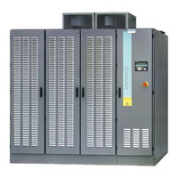
Siemens SINAMICS GM150 Operating And Installation Instructions (258 pages)
Medium-Voltage Drive
Brand:
Siemens
| Category:
DC Drives
| Size: 44.53 MB
Table of Contents
Edition
4
Table of Contents
5
About These Instructions
17
Introduction
17
Qualified Personnel
19
Safety Instructions
19
The Five Safety Rules
19
Warning Symbol on the Device
19
Safe Handling
20
Electromagnetic Fields in Electrical Power Engineering Installations
23
Components that Can be Destroyed by Electrostatic Discharge (ESD)
24
Information for Nominated Persons in Control of an Electrical Installation
25
Proper Usage
25
Security Information
26
Grounding Concept
27
Installation Site Safety
27
Measures for Operator Protection in Electromagnetic Fields
28
Residual Risks
28
Applications
31
Description
31
Safety Components and Functions
31
Safety Concept
31
External Safety Components
32
Protection and Monitoring Functions of Internal Components
32
Components
33
Design
33
Protection and Monitoring Functions for External Components
33
Design of the Basic Line Module
34
Design of the Motor Module
35
Description of the Components
36
Gating
36
Operating Principle
36
SINAMICS Control Unit
36
Terminal Modules
36
Electromechanical Door Interlock System
37
Precharging
37
Circuit-Breaker (Provided by the Customer)
38
Converter Transformer
38
Make-Proof Grounding Switch
38
Power Stack Adapter
39
Actual Value Acquisition
41
Common Power Supply
41
Field of Application
41
Design
42
Connections
43
Interface Description
43
DM10 Diagnostics Module
44
Functions
44
Figure 3-8 Logical Design of the DM10 Diagnosis Module
45
Interface Description of the Connectors
46
Measuring Socket Assignment
46
Table 3-1 Connector -X231
47
Table 3-2 Connector -X232
48
Table 3-3 Connectors -X1 and -X31
48
Table 3-4 Connector -X32
49
Table 3-5 Connector -X33
49
Table 3-6 Connector -X34
49
Table 3-7 Connector -X35
49
Table 3-8 Connector -X36
50
Table 3-9 Deionized Water Requirements
53
Auxiliary Voltage Supply 3 AC 200 V 50 Hz (Option C30)
54
Description of Options
54
NAMUR Terminal Strip (Option B00)
54
Isolation Amplifiers for Optional Analog Inputs (Option E86)
55
Isolation Amplifiers for Optional Analog Outputs (Option E87)
55
Suitable for Marine Use with Individual Certificate from Lloyds Register (LR) (Option E21)
55
Can Bus Interface (Option G20)
56
Devicenet Interface (Option G23)
56
Modbus Plus Interface (Option G21)
56
Modbus RTU Slave Interface (Option G22)
56
Teleservice Connection TS Adapter II Analog Modem (Option G25)
56
Teleservice Connection TS Adapter II ISDN Modem (Option G35)
56
1X Temperature Sensor Evaluation Unit TM150 (Option G51)
57
Additional Terminal Module TM31 (Option G61)
57
Additional Terminal Module TM15 (Option G63)
58
Display Instruments in the Cabinet Door for Voltage, Current, Speed, and Output Plus Indicator Lamps (Option K21)
58
Indicator Lamps in the Cabinet Door (Option K20)
58
Output Reactor (Option L08)
59
Power Unit with Internal Cooling (Option K66)
59
Sensor Module SMC30 (Option K50)
59
DV/Dt Filter (Option L10)
60
DV/Dt Filter (Option L11)
62
Automatic Restart Function (Option L32)
63
Line-Side Grounding Switch (Option L48)
64
Motor-Side Grounding Switch (Option L49)
64
Cabinet Illumination and Service Socket in Closed-Loop Control Unit (Option L50)
65
Circuit Breaker at the Drive Output (Option L52)
65
Disconnector at the Drive Output (Option L51)
65
Uninterruptible Power Supply (UPS) (Option L53)
65
Anti-Condensation Heating (Option L55)
66
EMERGENCY STOP Category 1 (Option L60)
66
Braking Module (Option L72)
67
Power Cable Connection at the Drive Input from above (Option M13)
67
Safety Locking System (Option M10)
67
Table 3-10 Braking Power Braking Module with External Brake Resistor
67
Extended Dust Protection (Option M16)
68
IP54 Degree of Protection (Option M54)
68
Redundant Fan in the Power Unit (Option M61)
68
Signal and Control Cable (Max. 2.5 MM²) (Option M32)
68
Suitability for Marine Use (Option M66)
68
Capacitor Release (Option N20)
69
Power Cable Connection at the Drive Output from above (Option M78)
69
Controlled Outgoing Circuit for Auxiliary Equipment 400 V 3 AC (Option N30)
70
Sine-Wave Filter (Option Y15)
71
Table 3-11 Max. Permissible Cable Lengths
71
Checking the Delivery
73
Inspections When Receiving the Delivery
73
Preparations for Use
73
Requirements for Installation Location
73
Checking Shock and Tilt Indicators
74
Scope of Delivery
74
Checking the Load Handling Attachments
75
Transport Markings
76
Transport Requirements
76
Transportation
76
Observe Center of Gravity
77
Transport with a Fork-Lift Truck
77
Transport with a Crane
78
Using Lifting Rods
78
Voltage Monitoring
51
Operating Principle of the Re-Cooling Unit
52
Re-Cooling Unit
52
Re-Cooling Unit Requirements
52
Customer Terminal Strips
53
The Internal Deionized Water Circuit
53
Signal Processing
50
Figure 4-3 Lifting Bar Label
79
Transporting Transportation Units Packed in Boxes
80
Removing the Packaging
81
Unpacking
81
Lifting the Cabinet off the Transport Pallet
82
Removing Load Securing Devices
82
Opening Doors in Preparation for Use
83
Checking the Shock and Tilt Indicators Inside the Cabinet
84
Emptying the Drive
84
Storage
84
Storing a Device
85
Installation
87
Safety Instructions for Assembly
87
Removing Transport Rails
88
Screwing the Transport Units Together
88
Tools Required
88
Figure 5-2 Screwing Cabinets Together
89
Connecting Cabinets
90
Connecting to the Foundation
90
Connecting the DC Bus
91
Connecting the Interface Terminals
92
Connecting the Water Circuits
93
Removing the Dust Protection Cover
94
Tools Required
94
Removing the Dust Protection Cover of the Closed-Loop Control Cabinet
95
Removing the Dust Protection Cover of the Inverter Cabinet
96
Removing the Dust Protection Cover of the Rectifier Cabinet
97
Installing the Battery of the Uninterruptible Power Supply
99
Figure 5-11 Install Battery
100
Electrical Connection
101
Safety Instructions for Electrical Connections
101
Electromagnetic Compatibility
103
Figure 6-1 Shield Connection Using a Clip
105
Potential Concept
106
Connection
107
Electrical Requirements
107
Manually Unlocking Power-Unit Doors
107
Table 6-1 Dimensioning Cables
107
Table 6-2 Cable Cross-Sections
107
Connecting Power Cables
108
Preparations for Connecting the Power Cables
108
Connect the Power Cable to the Motor and the Supply System
109
Figure 6-5 Connection of the Supply-System Power Cable
110
Table 6-3 Drive and Motor Connection Terminals
110
Connect the Auxiliary Voltage
111
Connecting Ground
111
Connecting the Control Cables to the Circuit-Breaker for the Capacitor Release (Option N20)
112
Connecting the Encoder to the SMC30 Sensor Module
113
Figure 6-8 Connecting the External Encoder to the SMC30 Sensor Module
114
Connecting the Re-Cooling Unit to the Drive
115
Interconnecting Optional Connections
115
Fastening the Cable Ducts with Cable Ties
116
Start-Up
117
Venting the Converter
117
Description and Configuration of the PROFIBUS Interface
119
Hardware Components Required for PROFIBUS Communication
119
PROFIBUS Interface, Diagnostics Leds, Address Switches
120
Table 7-1 PROFIBUS Interface X126
121
Table 7-2 Description of the DP1 Leds
121
Connecting PROFIBUS Cables
122
Setting the PROFIBUS Address Switches
123
Requirements for Communication Via PROFIBUS
124
Operation
125
Safety Instructions for Operation
125
AOP30 Operator Panel
126
General Information about the AOP30 Operator Panel
126
Operation Via the AOP30 Operator Panel
126
Basic Operation of the AOP 30
128
Buttons of the AOP30
128
Figure 8-2 Menu Structure of the AOP 30
129
Configuration of the AOP30 Operator Panel
131
Define Operation Screen
131
Table 8-1 List of Signals for the Operation Screen
134
Table 8-2 Scaling
135
Table 8-3 Overview of Important Parameters (Equipment Commissioning)
150
Commissioning / Service Drive Commissioning
152
Table 8-4 Drive Object Vectormv
152
Commissioning / Service - AOP Settings
153
Commissioning / Service - AOP Diagnostics
157
Language
161
Parameter
161
Parameters
161
Parameter Types
162
Functions
163
Setpoint Channel
163
Setpoint Channel and Closed-Loop Control
163
Control Settings
135
Inhibit Functions
138
Menu Description and Setting Options
141
Operation Screen
141
Parameterization
143
Fault/Alarm Memory
146
Commissioning / Service Device Commissioning
148
Table 8-5 Parameter
164
Table 8-6 Parameter
164
Table 8-7 Parameter
164
Table 8-8 Parameter
164
Table 8-9 Leds of the Power Stack Adapters
186
Diagnostics Via Parameters
187
High Snubber Circuit Capacitor Voltages
193
Maintenance
193
Safety Instructions for Maintenance
193
Grounding the System
196
Grounding with a Grounding Device
196
Grounding Using a Make-Proof Grounding Switch
198
Opening the Doors
198
Manually Unlocking Power Unit Doors
199
Opening the Power Unit Doors for Maintenance Work
199
Secure Locking System (Option M10)
200
Checklist for Preventive Maintenance Work
201
Inspection
201
Preventive Maintenance
201
Equipment for Visual Inspections
202
Visual Inspections
202
Checking Hoisting Solenoids and Security Bolts
203
Checking the Cable and Screw Terminals
203
Checking the Capacitor Release (Option N20)
203
Checking the Isolating Clearances
203
Checking the Plug Connections
203
Fan Maintenance
204
Maintenance
204
Replacing the Fan (Option L08)
204
Replacing the Back-Up Battery of the AOP30 Operator Panel
205
Load Operator Panel Firmware, Parameter and Signal Descriptions
207
Cleaning
208
Cleaning Aluminum Parts
208
Removing Dust Deposits
208
Repairs
209
Torques
210
Replacing the Diode Module
211
Vector Control
166
U/F Control
169
Analog and Digital Inputs/Outputs
170
Analog Outputs
170
Digital Outputs
173
Digital Inputs/Outputs
174
Additional Settings for Analog Outputs
175
Scaling the Input Signal of the Analog Inputs
178
Insulation Monitoring
179
Monitoring Functions and Protective Functions
179
DC-Link Short-Circuiter
180
Tripping of the Circuit-Breaker in Case of Undervoltage
180
VDC-Max Closed-Loop Control
181
Controlled Stop, EMERGENCY STOP Category 1
183
Fan Monitoring
183
Speed Monitoring with Incremental Encoder
183
External Alarms and Faults
184
Fault and System Messages
184
Message from the Grounding Switch
184
Diagnosis
185
Indicating and Rectifying Faults
185
Diagnostics Via Leds
186
Figure 9-8 Release the Screw Connection of the Line Supply Connection Busbar
212
Figure 9-10 Removing the Retainers for the Water Hoses
213
Replacing the Powercard
214
Figure 9-11 Releasing Screw Connections
215
Figure 9-12 Removing the Powercard: Remove the Retainers for the Water Connections
216
Replacing the Operator Panel
218
Replacing the Compactflash Card
219
Replacing the Precharging Transformer
219
Replacing the Precharging Rectifier
221
Replacing the AVT Combination Module
222
Replace the Sponge for the Leak Detector
223
Replacing Fuses
223
Replacing the Power Stack Adapter
224
Spare Parts
227
Disposal
229
Disposing of Packaging Material
229
Removing Device Components and Old Devices
229
Service & Support
231
B.1 Technical Specifications
233
Notes about Technical Specifications
233
Standards and Regulations
233
Technical Data and Drawings
233
Technical Specifications
233
Connection Variant: 24-Pulse Supply with Series Connection of Two Basic Line Modules (Option N15, Y15)
234
General Technical Specifications of the Drive
234
Series Connection Variant of Basic Line Modules (Option N15)
234
Table B-3 Cooling
235
Table B-4 Closed-Loop Control Related Properties
236
Technical Specifications of the Common Power Supply
237
Control Pulpit Interface (Terminal Modules TM31 and TM15)
238
Technical Specifications of the Diagnostics Module DM10
238
Terminal Assignments
238
Terminal Assignment of the NAMUR Terminal Strip (Option B00)
239
Circuit-Breaker Interface
240
B.2.4 Interfaces of the Power Stack Adapter
241
Gating of the Power Semiconductors
241
Interfaces of the Power Stack Adapter
241
Selecting Safe Torque off
241
Actual Value Channels
242
B.2.4.3 Actual Value Channels
242
DRIVE-Cliq Interface
242
Trip Line
242
Analog and Digital Outputs
243
Switch for the Analog Inputs
243
Analog and Digital Inputs and Temperature Sensor Connections
244
Electronics Power Supply
245
Checklists and Forms
247
Mechanical Installation: Checklist
247
Checklist for Electrical Installation
248
Index
253
Advertisement
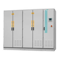
Siemens SINAMICS GM150 Operating Instructions & Installation Instructions (222 pages)
Medium-Voltage Drive
Brand:
Siemens
| Category:
DC Drives
| Size: 5.39 MB
Table of Contents
Edition
4
Table of Contents
5
About These Instructions
15
Introduction
15
Qualified Personnel
17
Safety Instructions
17
The 5 Safety Rules
17
Warning Symbol on the Device
17
Safe Handling
18
Electromagnetic Fields in Electrical Power Engineering Installations
20
Components that Can be Destroyed by Electrostatic Discharge (ESD)
21
Figure 2-1 ESD Information
22
Information for Nominated Persons in Control of an Electrical Installation
22
Proper Usage
22
Grounding Concept
23
Installation Site Safety
24
Measures for Operator Protection in Electromagnetic Fields
24
Residual Risks
25
Security Information
26
Applications
29
Description
29
Safety Components and Functions
29
Safety Concept
29
External Safety Components
30
Protection and Monitoring Functions of Internal Components
30
Components
31
Design
31
Protection and Monitoring Functions for External Components
31
Design of the Basic Line Module
32
Figure 3-2 Basic Line Module with Diodes in 12-Pulse Configuration
33
Figure 3-3 Motor Module
33
Description of the Components
34
Gating
34
Operating Principle
34
SINAMICS Control Unit
34
Figure 3-4 Overview of PSA Interfaces
35
Power Stack Adapter
35
Electromechanical Door Interlock System
36
Precharging
36
Terminal Modules
36
Circuit-Breaker (Provided by the Customer)
37
Converter Transformer
37
Make-Proof Grounding Switch
37
Actual Value Acquisition
38
Common Power Supply
39
Design
39
Field of Application
39
Figure 3-5 AVT Combination Module
39
Figure 3-6 Design When Using Igbts
39
Figure 3-7 Overview
40
DM10 Diagnostics Module
41
Figure 3-8 Schematic Diagram: Printed Circuit Board of the Diagnostics Module
41
Functions
41
Figure 3-9 Logical Design of the DM10 Diagnosis Module
42
Signal Processing
42
Voltage Monitoring
43
Auxiliary Voltage Supply 3 AC 200 V 50 Hz (Option C30)
44
Customer Terminal Strips
44
Description of Options
44
NAMUR Terminal Strip (Option B00)
44
CAN Bus Interface (Option G20)
45
Isolation Amplifiers for Optional Analog Inputs (Option E86)
45
Isolation Amplifiers for Optional Analog Outputs (Option E87)
45
Modbus Plus Interface (Option G21)
45
Modbus RTU Slave Interface (Option G22)
45
1X Temperature Sensor Evaluation Unit TM150 (Option G51)
46
Additional Terminal Module TM31 (Option G61)
46
Devicenet Interface (Option G23)
46
Teleservice Connection TS Adapter II Analog Modem (Option G25)
46
Teleservice Connection TS Adapter II ISDN Modem (Option G35)
46
Additional Terminal Module TM15 (Option G63)
47
Indicator Lamps in the Cabinet Door (Option K20)
47
CU320-2 DP Control Unit (Option K90)
48
Display Instruments in the Cabinet Door for Voltage, Current, Speed, and Output Plus Indicator Lamps (Option K21)
48
Output Reactor (Option L08)
48
Sensor Module SMC30 (Option K50)
48
Automatic Restart Function (Option L32)
49
Line-Side Grounding Switch (Option L48)
49
Cabinet Illumination and Service Socket in Closed-Loop Control Unit (Option L50)
50
Circuit Breaker at the Drive Output (Option L52)
50
Disconnector at the Drive Output (Option L51)
50
Motor-Side Grounding Switch (Option L49)
50
Anti-Condensation Heating (Option L55)
51
EMERGENCY STOP Category 1 (Option L60)
51
Uninterruptible Power Supply (UPS) (Option L53)
51
Braking Module (Option L72)
52
Table 3-1 Braking Power Braking Module with External Brake Resistor
52
Dust Protection (Option M11)
53
Power Cable Connection at the Drive Input from above (Option M13)
53
Safety Locking System (Option M10)
53
Signal and Control Cable (Max. 2.5 MM²) (Option M32)
53
Capacitor Release (Option N20)
54
IP42 Degree of Protection (Option M42)
54
Power Cable Connection at the Drive Output from above (Option M78)
54
Preparation for Connection to an External Exhaust Air System with Internal Cabinet Fans (Option M64)
54
Redundant Fan in the Power Unit (Option M61)
54
Braking Resistor (Option Y73)
55
Controlled Outgoing Circuit for Auxiliary Equipment 400 V 3 AC (Option N30)
55
Inspections When Receiving the Delivery
57
Preparations for Use
57
Requirements for Installation Location
57
Scope of Delivery
57
Checking Shock and Tilt Indicators
58
Checking the Load Handling Attachments
59
Figure 4-1 Example of Attaching and Displaying the Shock and Tilt Indicators
59
Transport Markings
60
Transport Requirements
60
Transportation
60
Figure 4-2 Example Illustration of Centers of Gravity
61
Observe Center of Gravity
61
Transport with a Fork-Lift Truck
61
Transport with a Crane
62
Using Lifting Rods
62
Figure 4-3 Lifting Bar Label
63
Figure 4-4 Securing the Lifting Rods
63
Transporting Transportation Units Packed in Boxes
64
Figure 4-5 Transporting a Transportation Unit (Still in Packaging) with a Crane
65
Removing the Packaging
65
Unpacking
65
Lifting the Cabinet off the Transport Pallet
66
Removing Load Securing Devices
66
Figure 4-6 Example: Label with Instructions for Opening the Doors
67
Opening Doors in Preparation for Use
67
Checking the Shock and Tilt Indicators Inside the Cabinet
68
Storage
68
Storing a Device
68
Storing Fans
70
Installation
71
Safety Instructions for Assembly
71
Figure 5-1 Removing the Support Rails
72
Removing Transport Rails
72
Screwing the Transport Units Together
72
Tools Required
72
Connecting to the Foundation
73
Figure 5-2 Screwing Cabinets Together
73
Connecting the Grounding Bars
74
5.7 Connecting the DC Bus
75
Figure 5-3 Grounding Bar
75
Preparation
75
5.7 Connecting the DC Bus
76
Figure 5-4 Connecting the DC Bus
76
Connecting the Interface Terminals
77
Ensuring Cooling Air
77
Figure 5-5 Remove the Screws
77
Installing the Battery of the Uninterruptible Power Supply
77
Figure 5-6 Install Battery
78
Electrical Connection
79
Safety Instructions for Electrical Connections
79
Electromagnetic Compatibility
81
Figure 6-1 Shield Connection Using a Clip
83
Figure 6-2 Bridging Shield Gaps
83
Figure 6-3 Potential Concept
84
Potential Concept
84
Connection
85
Electrical Requirements
85
Manually Unlocking Power-Unit Doors
85
Table 6-1 Dimensioning Cables
85
Table 6-2 Cable Cross-Sections
85
Connecting Ground
86
Figure 6-4 Grounding Lug
86
Preparations for Connecting the Power Cables
86
Connect the Power Cable to the Motor and the Supply System
87
Connecting Power Cables
87
Figure 6-5 Example: Connecting the Power Cables
87
Figure 6-6 Connection of the Supply-System Power Cable
89
Table 6-3 Drive and Motor Connection Terminals
89
Figure 6-7 Connecting the External Encoder to the SMC30 Sensor Module
92
Figure 6-8 Connection Example 1: HTL Encoder, Bipolar, with Reference Signal
92
Fastening the Cable Ducts with Cable Ties
93
Interconnecting Optional Connections
93
Description and Configuration of the PROFIBUS Interface
95
Start-Up
95
PROFIBUS Interface, Diagnostics Leds, Address Switches
96
Table 7-1 PROFIBUS Interface X126
97
Table 7-2 Description of the COM LED
97
Connecting PROFIBUS Cables
98
Setting the PROFIBUS Address
99
Requirements for Communication Via PROFIBUS
100
Operation
101
Safety Instructions for Operation
101
AOP30 Operator Panel
102
General Information about the AOP30 Operator Panel
102
Operating the Drive
102
Operation Via the AOP30 Operator Panel
102
Basic Operation of the AOP 30
104
Buttons of the AOP30
104
Figure 3-1 Design of the Power Unit
32
Design of the Motor Module
33
Connections
40
Connect the Auxiliary Voltage
90
Connecting the Control Cables to the Circuit-Breaker for the Capacitor Release (Option N20)
90
Connecting the Encoder to the SMC30 Sensor Module
91
Figure 8-2 Menu Structure of the AOP 30
105
Configuration of the AOP30 Operator Panel
107
Define Operation Screen
107
Table 8-1 List of Signals for the Operation Screen
109
Table 8-2 Scaling
111
Table 8-3 Overview of Important Parameters (Equipment Commissioning)
125
Commissioning / Service Drive Commissioning
127
Table 8-4 Drive Object Vectormv
127
Commissioning / Service - AOP Settings
128
Commissioning / Service - AOP Diagnostics
132
Language
136
Parameter
136
Parameters
136
Parameter Types
137
Functions
138
Setpoint Channel
138
Setpoint Channel and Closed-Loop Control
138
Inhibit Functions
114
Menu Description and Setting Options
116
Operation Screen
116
Parameterization
119
Fault/Alarm Memory
121
Commissioning / Service Device Commissioning
123
Control Settings
111
Table 8-5 Parameter
139
Table 8-6 Parameter
139
Table 8-7 Parameter
139
Table 8-8 Parameter
139
Vector Control
141
U/F Control
144
Analog and Digital Inputs/Outputs
145
Analog Outputs
145
Additional Settings for Analog Outputs
147
Scaling the Input Signal of the Analog Inputs
150
Digital Inputs/Outputs
151
Digital Outputs
152
Monitoring Functions and Protective Functions
153
Insulation Monitoring
154
DC-Link Short-Circuiter
155
Tripping of the Circuit-Breaker in Case of Undervoltage
155
VDC-Max Closed-Loop Control
156
Controlled Stop, EMERGENCY STOP Category 1
158
Fan Monitoring
158
Speed Monitoring with Incremental Encoder
158
Automatic Restart
159
External Alarms and Faults
160
Fault and System Messages
160
Message from the Grounding Switch
160
Diagnosis
161
Indicating and Rectifying Faults
161
Diagnostics Via Leds
162
Diagnostics Via Parameters
163
Maintenance
169
Safety Instructions for Maintenance
169
Grounding the System
171
Grounding with a Grounding Device
171
Grounding Using a Make-Proof Grounding Switch
173
Opening the Doors
174
Manually Unlocking Power Unit Doors
175
Opening the Power Unit Doors for Maintenance Work
175
Secure Locking System (Option M10)
176
Checklist
177
Inspection
177
Inspection and Maintenance
177
Cleaning
178
Checking the Filter Mats
179
Cleaning Aluminum Parts
179
Equipment for Visual Inspections
179
Visual Inspections
179
Checking Hoisting Solenoids and Security Bolts
180
Checking the Capacitor Release
180
Checking the Isolating Clearances
180
Checking the Cable and Screw Terminals
181
Checking the Capacitor Release
181
Checking the Plug Connections
181
Maintaining the Fan
182
Replacing Filter Mats
182
Replace the Fans
183
Load Operator Panel Firmware, Parameter and Signal Descriptions
184
Replacing the Back-Up Battery of the AOP30 Operator Panel
185
Repair
187
Torques
187
Replacing the AVT Combination Module
189
Replacing the Operator Panel
190
Replacing the Compactflash Card
191
Replacing the Diode Module
191
Figure 9-12 Release the Screwed Connection of the DC Link Busbar
192
Replacing the Powercard
193
Figure 9-15 Releasing Screw Connections
194
Replacing the Power Stack Adapter
195
Replacing Fuses
196
Replacing the Current Transformer
196
Door Interlock System
197
Replacing the Precharging Transformer
197
Replacing the Precharging Rectifier
199
Spare Parts
201
Disposal
203
Disposing of Packaging Material
203
Removing Device Components and Old Devices
203
Service & Support
205
B.1 Technical Specifications
207
Standards and Regulations
207
Technical Data and Drawings
207
Technical Specifications
207
Checklists and Forms
209
Mechanical Installation: Checklist
209
Checklist for Electrical Installation
210
Index
215
Advertisement
Related Products
Siemens SINAMICS G110
Siemens SINAMICS G120D
Siemens SINAMICS G110D
Siemens SINAMICS GL150
Siemens Sinamics GM150 6SL3835-2LN44-2AA0
Siemens SINAMICS PERFECT HARMONY GH150
Siemens SINAMICS G115D
Siemens SINAMICS PERFECT HARMONY GH150 6SL3826
Siemens SINAMICS S150
Siemens SINAMICS G
Siemens Categories
Industrial Equipment
Controller
Control Unit
Oven
Washer
More Siemens Manuals
Login
Sign In
OR
Sign in with Facebook
Sign in with Google
Upload manual
Upload from disk
Upload from URL