Sign In
Upload
Manuals
Brands
Genie Manuals
Lifting Systems
GS-3390
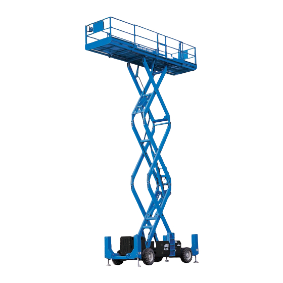
Genie GS-3390 Manuals
Manuals and User Guides for Genie GS-3390. We have
7
Genie GS-3390 manuals available for free PDF download: Service Manual, Service And Repair Manual, Maintenance Manual, Operator's Manual
Genie GS-3390 Service Manual (348 pages)
Brand:
Genie
| Category:
Scissor Lifts
| Size: 7.08 MB
Table of Contents
Introduction
2
Serial Number Legend
3
Safety Rules
5
Table of Contents
7
Machine Specifications
15
Performance Specifications
16
Hydraulic Specifications
16
Hydraulic Component Specifications
17
Manifold Component Specifications
19
Valve Coil Resistance Specifications
19
Ford LRG-425 EFI Engine
20
Deutz F4L 1011F Engine
21
Deutz F3L 1011F Engine
22
Deutz F3L 2011 Engine
23
Deutz D2011L03I Engine
23
Hydraulic Hose and Fitting Torque Specifications
24
Part
26
Pre-Delivery Preparation Report
28
Maintenance Inspection Report
31
Checklist a Procedures
33
Inspect the Manuals and Decals
33
Perform Pre-Operation Inspection
34
Perform Function Tests
34
Perform Engine Maintenance - Ford Models
35
Perform Engine Maintenance - Deutz Models
35
Perform 30 Day Service
36
Perform Engine Maintenance - Deutz Models
36
Perform Engine Maintenance - Ford Models
37
Check the Hydraulic Return Filter Condition Indicator (if Equipped)
37
Perform Engine Maintenance - Deutz 1011F Models
38
Drain the Fuel Filter/ Water Separator - Deutz Models
38
Perform Engine Maintenance - Ford Models
39
Checklist B Procedures
40
Inspect the Battery
40
Inspect the Electrical Wiring
41
Perform Engine Maintenance - Deutz 1011F Models
42
Check the Exhaust System
42
Inspect the Engine Air Filter
43
Check and Adjust the Engine RPM
44
Confirm the Proper Brake Configuration
46
Inspect the Tires and Wheels (Including Lug Nut Torque)
46
Check the Oil Level in the Drive Hubs
47
Test the Key Switch
47
Test the Emergency Stop
48
Test the Automotive-Style Horn
48
Test the Fuel Select Operation - Ford Models
49
Test the Drive Brakes
50
Test the Drive Speed - Stowed Position
50
Test the Drive Speed - Raised Position
51
Perform Hydraulic Oil Analysis
52
Inspect the Fuel and Hydraulic Tank Cap Venting Systems
53
Replace the Engine Air Filter Element - Ford Models
54
Perform Engine Maintenance - Ford Models
54
E Checklist C Procedure
55
Test the Platform Overload System (if Equipped)
55
Replace the Engine Air Filter Element - Deutz Models
56
Perform Engine Maintenance - Deutz Models
57
Replace the Hydraulic Tank Breather Cap - Models with Optional Hydraulic Oil
57
Perform Engine Maintenance - Ford Models
57
Checklist D Procedures
58
Check the Scissor Arm Wear Pads
58
Check the Free-Wheel Configuration
59
Replace the Drive Hub Oil
60
Replace the Fuel Filter / Water Separator - Deutz Models
60
Replace the Hydraulic Tank Return Filter
62
Perform Engine Maintenance - Deutz Models
63
C Checklist E Procedure
64
Test or Replace the Hydraulic Oil
64
Perform Engine Maintenance - Deutz 1011F Models
66
Perform Engine Maintenance - Ford Models
67
Perform Engine Maintenance - Deutz Models
67
Perform Engine Maintenance - Deutz 2011 Models
68
Perform Engine Maintenance - Ford Models (before Serial Number GS9003-41369)
68
Platform Controls
70
Circuit Boards
71
Joystick Controller
71
Controller Adjustments (before Serial Number GS9003-41523)
73
Software Configuration (before Serial Number GS9003-41523)
79
Platform Components
83
Platform
83
Platform Extension Deck
85
Scissor Components
86
Scissor Assembly, GS-3390
87
Scissor Assembly, GS-4390
93
Scissor Assembly, GS-5390
103
Wear Pads
115
Lift Cylinder(S)
117
RPM Adjustment
121
Engine Fault Codes - Ford Models
121
Flex Plate
121
Oil Temperature and Oil Pressure Switches - Deutz Models
125
Coolant Temperature and Oil Pressure Switches - Ford Models
126
Ground Controls
127
Auxiliary Platform Lowering
127
Controller Adjustments (after Serial Number GS9003-41522)
127
Software Configuration (after Serial Number GS9003-41522)
138
Level Sensor - Models Without Outriggers (before Serial Number 41158)
142
Level Sensor - Models Without Outriggers (after Serial Number 41157)
145
Level Sensor - Models with Outriggers
147
Engine Fault Codes - Ford Models
152
Hydraulic Pumps
154
Lift/Steer Pump
154
Drive Pump
156
Manifolds
157
Function Manifold Components - Models with Outriggers (before Serial Number 40519)
158
Function Manifold Components - Models with Outriggers (after Serial Number 40518)
160
Function Manifold Components - Models Without Outriggers (before Serial Number 40519)
162
Function Manifold Components - Models Without Outriggers (after Serial Number 40518)
164
Drive Manifold Components (before Serial Number GS9004-41691)
166
Drive Manifold Components (after Serial Number GS9004-41690)
168
Oscillate Manifold Components (Optional after Serial Number GS9004-41690)
170
Valve Adjustments - Function Manifold
172
Valve Adjustments - Drive Manifold
174
Generator Manifold Components
176
Valve Adjustments - Generator Manifold
177
Valve Coils
178
Fuel and Hydraulic Tanks
180
Fuel Tank
180
Hydraulic Tank
181
Steer Axle Components
183
Yoke and Drive Motor
183
Steer Cylinder
185
Tie Rod
186
Oscillating Axle Option (after Serial Number GS9004-41690)
187
Non-Steer Axle Components
188
Drive Motor and Brake
188
Drive Hub
189
Oscillating Axle
189
Outrigger Components
190
Outrigger Cylinder
190
Platform Overload Components
191
Platform Overload System
191
Fault Code Chart (before Serial Number GS9003-41523)
203
Fault Code Chart (after Serial Number GS9003-41522)
205
Ford Engine ECM Fault Code Chart (before Serial Number GS9003-41369)
208
Ford Engine ECM Fault Code Chart (after Serial Number GS9003-41368)
210
Electronic Control Module Layout (before Serial Number GS9003-41523)
216
A Electronic Control Module Pin-Out Legend
217
Electronic Control Module Layout (after Serial Number GS9003-41522)
218
Electronic Control Module Pin-Out Legend (after Serial Number GS9003-41522)
219
Ford Engine Relay Layout
220
Wiring Diagram - Platform Control Box (before Serial Number GS9003-41523)
221
Wiring Diagram - Platform Control Box (after Serial Number GS9003-41522)
222
Electrical Schematics Abbreviation and Wire Color Legends
223
Limit Switch Legend
224
Electrical Symbols Legend
226
A Electrical Schematic - Platform Overload (Option)
227
(Before Serial Number GS9003-41523)
227
Wiring Harness - Ford LRG-425 EFI (before Serial Number GS9003-41369)
228
Wiring Harness - Ford LRG-425 EFI (from Serial Number GS9003-41369 to GS9004-41693)
229
Wiring Harness - Ford LRG-425 EFI (after Serial Number GS9004-41693)
230
Electrical Schematic - Ford Models (before Serial Number 40428)
234
Electrical Schematic - Ford Models (from Serial Number 40428 to 40793)
238
Electrical Schematic - Ford Models (from Serial Number 40794 to 40995)
242
Electrical Schematic - Ford Models (from Serial Number 40996 to 41065)
246
(From Serial Number GS9003-41523 to GS9004-41693)
258
(From Serial Number GS9004-41694 to GS9005-42143)
262
(From Serial Number GS9005-42144 to GS9005-42203)
266
(From Serial Number GS9005-42204 to GS9005-42685)
270
(From Serial Number GS9003-41523 to GS9004-41693)
274
(From Serial Number GS9004-41694 to GS9005-42143)
278
(From Serial Number GS9005-42412 to GS9005-42685)
290
Electrical Schematic - Deutz Models (before Serial Number 40428)
294
(From Serial Number GS9003-41523 to GS9005-42143)
318
(From Serial Number GS9003-41523 to GS9005-42143)
319
(From Serial Number GS9005-42412 to GS9005-42685)
334
Hydraulic Schematics Component Call-Out Legend
338
Hydraulic Symbols Legend
339
Hydraulic Schematic (before Serial Number 40519)
341
Hydraulic Schematic (from Serial Number 40519 to GS9004-41690)
341
Hydraulic Schematic (from Serial Number GS9004-41691 to GS9005-42685)
342
Advertisement
Genie GS-3390 Service Manual (277 pages)
Brand:
Genie
| Category:
Scissor Lifts
| Size: 3.02 MB
Table of Contents
Introduction
2
Serial Number Information
2
Revision History
3
Serial Number Legend
5
Safety Rules
6
Table of Contents
8
GS-84 • GS-90 Part
16
Specifications
17
Machine Specifications
17
Performance Specifications
18
Hydraulic Specifications
19
Hydraulic Component Specifications
20
Manifold Component Specifications
21
Valve Coil Specifications
21
Ford LRG-425 EFI Engine
22
Ford DSG-423 EFI Engine
23
Deutz F3L 2011 Engine Deutz D2011L03I Engine
24
Hydraulic Hose and Fitting Torque Specifications
26
Scheduled Maintenance Procedures
29
Pre-Delivery Preparation Report
30
Maintenance Inspection Report
33
Checklist a Procedures
35
Inspect the Manuals and Decals
35
Perform Pre-Operation Inspection
36
Perform Function Tests
36
Perform Engine Maintenance - Ford Models
37
Perform Engine Maintenance - Deutz Models
37
Scheduled Maintenance Procedures , Continued
38
Test the Oscillate Axle - GS-90 Models
38
Perform 30 Day Service
39
Perform Engine Maintenance - Deutz Models
39
Perform Engine Maintenance - Ford Models
39
Drain the Fuel Filter/ Water Separator - Deutz Models
40
Replace the Drive Hub Oil
41
Perform Engine Maintenance - Ford Models
41
Checklist B Procedures
42
Inspect the Battery
42
Inspect the Electrical Wiring
43
Inspect the Engine Air Filter
44
Check and Adjust the Engine RPM
45
Check the Exhaust System
46
Confirm the Proper Brake Configuration
47
Inspect the Tires, Wheels and Lug Nut Torque
47
Check the Drive Hub Oil Level and Fastener Torque
48
Test the Key Switch
48
Test the Emergency Stop
49
Test the Automotive-Style Horn
49
Test the Fuel Select Operation - Ford Models
50
Test the Drive Brakes
51
Test the Drive Speed - Stowed Position
51
Test the Drive Speed - Raised Position
52
Check the up Limit Switch Drive Cutout and Outriggers GS-5390
53
Perform Hydraulic Oil Analysis
54
Inspect the Fuel and Hydraulic Tank Cap Venting Systems
54
Replace the Engine Air Filter Element - Ford Models
55
Perform Engine Maintenance - Ford Models
56
Scheduled Maintenance Procedures , Continued
57
Checklist C Procedures
57
Test the Platform Overload System (if Equipped)
57
Down Limit Switch Descent Delay (if Equipped)
58
Replace the Engine Air Filter Element - Duetz Models
59
Replace the Fuel Filter/Water Separator - Deutz Models
60
Perform Engine Maintenance - Deutz Models
61
Replace the Hydraulic Tank Breather Cap - Models with Optional Hydraulic Oil
61
Perform Engine Maintenance - Ford Models
61
Checklist D Procedures
62
Check the Scissor Arm Wear Pads
62
Check the Free-Wheel Configuration
63
Replace the Drive Hub Oil
64
Replace the Hydraulic Filters
64
Test the Oscillate Axle - GS-90 Models
66
Perform Engine Maintenance - Deutz Models
69
Checklist E Procedures
70
Test or Replace the Hydraulic Oil
70
Perform Engine Maintenance - Ford Models
72
Perform Engine Maintenance - Deutz Models
73
Repair Procedures
76
Platform Controls
76
Circuit Boards
76
Platform Components
77
Platform
77
Platform Extension Deck
79
Scissor Components
80
Scissor Assembly, GS-3384 and GS-3390
81
Scissor Assembly, GS-4390
87
Scissor Assembly, GS-5390
95
Wear Pads
102
Lift Cylinder(S)
104
Engines
109
RPM Adjustment
109
Engine Fault Codes - Ford Models
109
Engine Repair
109
Flex Plate
110
Ground Controls
115
Auxiliary Platform Lowering
115
Controller Adjustments
115
Software Configuration
126
Level Sensor - Models Without Outriggers
132
Level Sensor - Models with Outriggers
134
Engine Fault Codes - Ford Models
139
Hydraulic Pumps
141
Lift/Steer Pump
141
Drive Pump
143
Repair Procedures , Continued
144
Manifolds
144
Function Manifold Components - Models with Outriggers
146
Function Manifold Components - Models Without Outriggers
148
Drive Manifold Components
150
Oscillate Manifold Components, GS-90 Models (Option)
152
Welder Manifold Components, (Option)
154
Valve Adjustments - Function Manifold
156
Valve Adjustments - Drive Manifold
158
Generator Manifold Components
159
Valve Adjustments - Generator Manifold
160
Valve Coils
161
Fuel and Hydraulic Tanks
163
Fuel Tank
163
Hydraulic Tank
164
Steer Axle Components
166
Yoke and Drive Motor
166
Steer Cylinder
168
Oscillating Axle Option (GS-90 Models)
169
Non-Steer Axle Components
170
Drive Motor and Brake
170
Drive Hub
171
Oscillating Axle
171
Outrigger Components
172
Outrigger Cylinder
172
Platform Overload Components
173
Platform Overload System
173
Ford LRG425 ECM Fault Code Chart
188
Ford DSG423 ECM Fault Code Chart
193
Schematics
198
Electronic Control Module Layout
198
Electronic Control Module Pin-Out Legend
199
Ground Controls Wiring Panel Layout
200
Ford Engine Relay Layout
201
Wiring Diagram - Platform Control Box
202
Limit Switch Legend
203
Electrical Schematics Abbreviation and Wire Color Legends
204
Electrical Symbols Legend
205
Wiring Harness - Ford LRG-425 EFI (GS-84 Models before Serial Number GS8406-41197) (GS-90 Models before Serial Number GS9006-43481)
206
Wiring Harness - Ford DSG-423 EFI (GS-84 Models from Serial Number GS8406-41197 to GS8407-41311) (GS-90 Models from Serial Number GS9006-43481 to GS9007-43786)
208
Wiring Harness - Ford DSG-423 EFI (GS-84 Models after Serial Number GS8407-41311) (GS-90 Models after Serial Number GS9007-43786)
209
GS-84 Models after Serial Number
210
(GS-90 Models from Serial Number GS9006-42686 to GS9006-43480)
212
GS-84 Models from Serial Number GS8406-40833 to
212
(GS-84 Models from Serial Number GS8406-40833 to GS8406-41196)
214
(GS-90 Models from Serial Number GS9006-42686 to GS9006-43480)
214
(GS-90 Models from Serial Number GS9006-43481 to GS9007-43786)
216
(GS-84 Models from Serial Number GS8406-41197 to GS8407-41311)
216
(GS-84 Models from Serial Number GS8406-41197 to GS8407-41311)
218
(GS-90 Models from Serial Number GS9006-43481 to GS9007-43786)
218
Schematics, Continued
220
(GS-84 Models after Serial Number GS8407-41311)
220
(GS-90 Models from Serial Number GS9007-43787 to GS9012-48127)
220
(GS-84 Models after Serial Number GS8407-41311)
221
(GS-90 Models after Serial Number GS9012-48127)
224
(GS-90 Models after Serial Number GS9012-48127)
226
(GS-84 Models from Serial Number GS8406-40833 to GS8406-41196)
228
(GS-84 Models after Serial Number GS8410-42031)
240
(GS-90 Models from Serial Number GS9010-47263 to GS9012-48127)
240
(GS-84 Models after Serial Number GS8410-42031)
241
(GS-90 Models from Serial Number GS9010-47263 to GS9012-48127)
241
(GS-84 Models after Serial Number GS8410-42031)
242
(GS-84 Models after Serial Number GS8410-42031)
244
(GS-90 Models after Serial Number GS9012-48127)
244
(GS-90 Models after Serial Number GS9012-48127)
246
(GS-84 Models after Serial Number GS8406-40833)
248
(GS-90 Models from Serial Number GS9006-42686 to GS9012-48127)
248
(GS-84 Models after Serial Number GS8406-40833)
250
Schematics, Continued
256
(GS-84 Models from Serial Number GS8406-40833 to GS8410-42031)
256
(GS-90 Models from Serial Number GS9006-42686 to GS9010-47262)
256
Wiring Diagram - 12 Kw Hydraulic Generator (Option)
268
Hydraulic Schematics Component Call-Out Legend
270
Hydraulic Schematic
272
(GS-90 Models from Serial Number GS9004-41691 to GS9007-45004)
272
Hydraulic Schematic
273
(GS-84 Models after Serial Number GS8407-41529)
274
(GS-90 Models after Serial Number GS9007-45004)
274
Genie GS-3390 Service And Repair Manual (193 pages)
scissor lift
Brand:
Genie
| Category:
Lifting Systems
| Size: 7.25 MB
Table of Contents
Table of Contents
7
Find a Manual for this Model
2
Revision History
3
Serial Number Legend
4
Safety Rules
5
Table of Contents
7
Specifications
13
Machine Specifications
13
Performance Specifications
14
Hydraulic Specification
15
Hydraulic Component Specifications
17
Manifold Component Specifications
18
Ford MSG-425 EFI Engine Specifications
19
Deutz D2011 L03I Engine Specifications
20
Deutz D 2.9 L4 Engine Specifications
21
Hydraulic Hose and Fitting Torque Specifications
23
Torque Procedure
24
Repair Procedures
25
Introduction
25
September
25
About this Section
26
Platform Controls
27
Circuit Board
27
How to Remove the Platform Controls Circuit Board
27
Electrocution/Burn Hazard
27
Platform Components
28
Platform
28
How to Remove the Platform
28
Platform Extension Deck
30
How to Remove the Platform Extension Deck
30
Scissor Components
31
Scissor Assembly, GS-3384 and GS-3390
32
How to Disassemble the Scissor Assembly
32
Bodily Injury Hazard. Spraying
32
How to Disassemble a Scissor Arm Pair
36
Scissor Assembly, GS-4390
38
How to Disassemble the Scissor Assembly
38
How to Disassemble a Scissor Arm Pair
42
Scissor Assembly, GS-5390
45
How to Disassemble the Scissor Assembly
45
How to Disassemble a Scissor Arm Pair
50
Wear Pads
51
How to Replace the Scissor Arm Wear Pad
51
How to Replace the Chassis Scissor Arm Wear Pads
52
Lift Cylinders
54
How to Remove the Lift Cylinder - GS-3384, GS-3390 and GS-4390
54
How to Remove the Lift Cylinder - GS-5390
56
Engines
58
RPM Adjustment - Deutz D2011L03I Models
58
Engine Fault Codes
58
Flex Plate
58
How to Remove the Flex Plate - Ford Models
58
How to Remove the Flex Plate - Deutz Models
59
How to Install the Flex Plate
60
Ground Controls
62
Auxiliary Platform Lowering
62
Controller Adjustments
62
How to Determine the Revision Level
63
How to Adjust the Stowed Drive Speed
63
How to Adjust the High Torque Drive Speed
64
How to Adjust the Raised Drive Speed
65
How to Adjust the Lift Speed
67
How to Adjust the Platform Lower Speed
68
How to Adjust the Platform Settling Speed
69
How to Adjust the Steer Speed
70
Software Configuration
70
Level Sensor - Models Without Outriggers
75
How to Install and Calibrate the Level Sensor - Models Without Outriggers
75
Level Sensor - Models with Outriggers
77
How to Install and Calibrate the Level Sensor - Models with Outriggers
77
Hydraulic Pump
81
Lift/Steer Pump
81
How to Remove the Lift/Steer Pump
81
Drive Pump
82
How to Remove the Drive Pump
82
How to Prime the Pump
83
How to Adjust the Pump Neutral
84
September
85
Manifolds
86
Function Manifold Components - Models with Outriggers
86
Function Manifold Components - Models Without Outriggers
88
Traction Manifold Components
90
Oscillate Manifold Components, GS-90 (Option)
92
Welder Manifold Components (Option)
94
Valve Adjustments - Function Manifold
95
How to Adjust the System Relief Valve
95
How to Adjust the Steer Relief Valve
96
Valve Adjustments - Traction Manifold
97
How to Adjust the Charge Pressure Relief Valve
97
Generator Manifold Components
98
Valve Adjustments - Generator Manifold
99
How to Adjust the Generator Voltage
99
Generator Relief Valve Manifold Components
100
Valve Coils
101
Gs-84 • Gs
102
Fuel and Hydraulic Tanks
103
Fuel Tank
103
September
103
Hydraulic Tank
104
Steer Axle Components
106
Yoke Assembly
106
How to Remove the Yoke and Drive Motor
106
How to Remove a Drive Motor
107
Steer Cylinder
108
Oscillating Axle Option - GS-90 Models
108
September
109
Non-Steer Axle Components
110
Drive Motor and Brake
110
How to Remove a Drive Motor and Brake
110
Drive Hub
111
How to Remove a Drive Hub
111
Oscillating Axle
112
Outrigger Components
113
Outrigger Cylinder
113
How to Remove an Outrigger Cylinder (if Equipped)
113
Platform Overload Components
114
Platform Overload System
114
How to Calibrate the Platform Overload System
114
Platform Overload Recovery Message (Software Version B3 and Later)
123
Fault Codes
125
Introduction
125
Before Troubleshooting
125
Read, Understand and Obey the Safety Rules and Operating Instructions in the Appropriate Operator's Manual on Your Machine
125
Be Sure that All Necessary Tools and Test
125
Equipment Are Available and Ready for Use
125
Hydraulic Oil Can Penetrate and Burn Skin. Loosen Hydraulic
125
Connections very Slowly to Allow
125
The Oil Pressure to Dissipate
125
Gradually. Do Not Allow Oil to
125
Control System Fault Codes
127
Fault Code Display - Deutz Models
131
How to Retrieve Active Engine Fault Codes Deutz D 2.9 L4 Models
131
Deutz D 2.9 L4 Models
132
Soft Key Functions and Icons - Deutz D 2.9 L4 Models
133
Main Menu Structure - Deutz D 2.9 L4 Models
134
Deutz D 2.9 L4 Engine Fault Codes
135
Ford MSG-425 Engine Fault Codes
146
How to Retrieve Ford Engine Fault Codes
146
How to Clear Engine Fault Codes from the ECM
146
Contact with Electrically Charged Circuits Could Result in Death or Serious Injury. Remove All Rings, Watches and Other Jewelry
146
Ford MSG-425 Engine Fault Codes
147
September
148
Schematics
153
Introduction
153
Section 5 Schematics
153
Electrical Symbols Legend
154
Hydraulic Symbols Legend
155
Electrical Component and Wire Color Legends
156
Ford Engine Relay Layout
158
Electronic Control Module Layout
159
Electronic Control Module Pin-Out Legend
160
Ground Controls Wiring Panel Layout
162
Wiring Diagram - Platform Control Box
163
Limit Switch Legend
164
Wiring Diagram - 12 Kw Hydraulic Generator (Option)
165
Electrical Schematics - Engine Harness
167
Ford MSG-425 EFI Engine Wire Harness
168
Deut D 2.9 L4 Engine Wire Harness
169
Hydraulic Schematics
171
Hydraulic Schematic
171
Hydraulic Schematic, to Serial Numbers GS8415-42316 and GS9015-50184
172
From Serial Numbers GS84154-42317 and GS9015-50185
174
Electrical Schematics - ANSI and CSA Models
177
Electrical Schematic, Ford Engine Models (ANSI/CSA)
178
Electrical Schematic, Deutz Engine Models (ANSI/CSA)
182
Electrical Schematics - as and CE Models
185
Electrical Schematic, Ford Engine Models (AS/CE)
186
Electrical Schematic, Deutz Engine Models (AS/CE)
190
Advertisement
Genie GS-3390 Maintenance Manual (97 pages)
Scissor Lifts
Brand:
Genie
| Category:
Lifting Systems
| Size: 2.64 MB
Table of Contents
Models Included in this Manual
3
Find Additional Manuals for Your Model
3
Glossary of Terms
4
Revision History
5
Safety Rules
7
Table of Contents
9
Performance Specifications
12
Function Speeds GS-30, GS-32, GS-46, GS-47
12
Function Speeds GS-69, GS-84, GS-90
12
Drive Speeds
14
Torque Specifications
15
Tires and Wheels
15
Battery Specifications
16
Battery Specifications - DC and be Models
16
Engine Specifications
17
Engine Operator and Maintenance Manuals
17
Deutz Engine Models
17
Perkins Engine Models
18
Ford Engine Models
18
Kubota Engine Models
19
Kohler Engine Models
19
GM Engine Models
20
Hydraulic Specifications
21
Hydraulic Relief Valves
21
Hydraulic and Drive Hub Fluid Capacities
23
Hydraulic Oil Specifications
24
Hydraulic Hose and Fitting Torque Specifications
27
Torque Procedure
28
Maintenance Procedures
31
Introduction
31
Maintenance Schedule
33
Pre-Delivery Preparation Report
34
Scheduled Maintenance Inspection Report - Scissor Lifts
35
Programmed Maintenance Inspection Report - Scissor Lifts
36
Commissioning Procedures
37
Perform 50 Hour Service
37
Perform Engine Maintenance - 50 Hours
37
Perform 150 Hour Service
38
Quarterly Maintenance Procedures
39
Check for Open Bulletins and Owner Registration
39
Battery Inspection
40
Check the Module Tray Latch Components
42
Inspect the Battery Balancer - GS-69 DC
43
Inspect the Electrical Wiring
44
Inspect the Electrical Contactor
45
DC and GS-69 be
45
Inspect the Voltage Inverter (if Equipped)
45
Test the Flashing Beacons (if Equipped)
46
Visual Inspection of the Hydraulic Oil
47
Inspect the Hydraulic Filters
48
Check the Exhaust System - Engine Models
49
Inspect the Fuel Tank Check Valve Venting System - GS-69 RT Gas Models
49
Test the Fuel Select Operation - Gasoline/Lpg Models
50
Check and Adjust the Engine RPM
51
Inspect the Tires, Wheels and Lug Nut Torque
53
Confirm the Proper Brake Configuration - GS-69, GS-84, GS-90
54
Test the Drive Brakes
54
Test the Drive Speed - Stowed Position
55
Test the Drive Speed - Raised Position
55
Test the down Limit Switch, Level Sensor and Pothole Limit Switches
56
And GS-47
56
Test the Platform Gate Proximity Switches and the Extension Deck Limit Switch - GS-2646 AV, GS-2646 AV35
60
Annual Maintenance Procedures
62
Check the Drive Hub Oil Level and Fastener Torque
62
Test the Function Pump - GS-69 be and GS-69 DC
62
Test the Oscillate Axle - GS-90
63
Test the down Limit Switch Descent Delay - GS-69, GS-84 and
66
Equipped)
66
Test the Platform Overload Pressure Transducer and Platform Height Sensor - GS-30, GS-32, GS-46 and GS-47 (if Equipped)
68
(If Equipped)
71
Test the Platform Overload System - GS-69 (if Equipped)
73
Test the Platform Overload System - GS-84 and GS-90 (if Equipped)
75
Programmed Maintenance Procedures
77
P0-1 Inspect the Engine Air Filter - GS-69 RT
77
P0-2 Grease the Steer Yokes - GS-30, GS-32, GS-46 and GS-47
78
P0-3 Deutz Engine Maintenance - under 1000 Hours
79
P0-4 Ford Engine Maintenance - under 1000 Hours
80
P0-5 Kohler Engine Maintenance - under 1000 Hours
81
P0-6 Kubota Engine Maintenance - under 1000 Hours
82
P0-7 Perkins Engine Maintenance - under 1000 Hours
83
P0-8 GM Engine Maintenance - under 1000 Hours
84
P1-1 Perform Engine Maintenance - 1000 Hours
85
P1-2 Replace the Drive Hub Oil - GS-69, GS-84 and GS-90
86
P2-1 Perform Engine Maintenance - 2000 Hours
86
P2-2 Replace the Hydraulic Filters
87
P2-3 Check the Free-Wheel Configuration - GS-84 and GS-90
88
P2-4 Check the Scissor Arm Wear Pads (and Slider Blocks, if Equipped)
90
P2-5 Grease the Steer Axle Wheel Bearings - GS-69 be and GS-69 DC
93
P2-6 Test or Replace the Hydraulic Oil
94
P3-1 Perform Engine Maintenance - 3000 Hours
95
Genie GS-3390 Operator's Manual (57 pages)
Brand:
Genie
| Category:
Lifting Systems
| Size: 7.47 MB
Table of Contents
Table of Contents
2
Introduction
3
Symbol and Hazard Pictorials Definitions
6
General Safety
8
Personal Safety
12
Work Area Safety
13
Legend
21
Controls
22
Inspections
27
Operating Instructions
40
Transport and Lifting Instructions
46
Maintenance
49
Specifications
53
Genie GS-3390 Operator's Manual (52 pages)
Scissor Lifts
Brand:
Genie
| Category:
Lifting Systems
| Size: 3.62 MB
Table of Contents
Table of Contents
2
Introduction
3
Gs-3384 • Gs-3390 • Gs-4390 • Gs
3
Symbol and Hazard Pictorials Definitions
7
General Safety
9
Personal Safety
11
Work Area Safety
12
Legend
20
Controls
21
Inspections
26
Operating Instructions
36
Transport and Lifting Instructions
42
Maintenance
45
Specifications
48
Genie GS-3390 Operator's Manual (36 pages)
Brand:
Genie
| Category:
Lifting Systems
| Size: 0.69 MB
Table of Contents
Table of Contents
2
Safety
3
Legend
10
Controls
11
Pre-Operation Inspection
13
Maintenance
15
Function Tests
18
Workplace Inspection
22
Operating Instructions
23
Transport and Lifting Instructions
27
Decals
30
Specifications
32
Genie GS-3384 and GS-3390 and GS-4390 and GS
32
Advertisement
Related Products
Genie GS-3268 DC
Genie GS-3268 RT
Genie GS-3369 RT
Genie GS-3369 DC GS-4069 DC
Genie GS-3369 BE
Genie Lift Guard GS-30
Genie Lift Guard GS-32
Genie GS-1930/32
Genie GS-4069 BE
Genie GS-2669 BE
Genie Categories
Garage Door Opener
Lifting Systems
Boom Lifts
Security Camera
Digital Camera
More Genie Manuals
Login
Sign In
OR
Sign in with Facebook
Sign in with Google
Upload manual
Upload from disk
Upload from URL