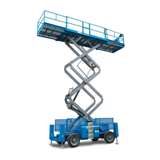
Genie GS-3384 Service And Repair Manual
Scissor lift
Hide thumbs
Also See for GS-3384:
- Service manual (298 pages) ,
- Operator's manual (57 pages) ,
- Maintenance manual (97 pages)
Table of Contents
Advertisement
Quick Links
Service and Repair Manual
GS-3384
GS -3390
GS - 4390
GS - 5390
Serial Number Range
from GS8413-42181 to
GS8415-42382
from GS8416F-42383 to
GS8416F-45499
from GS84F-45500
from GS9013-48427 to
GS9015-51063
from GS9016F-51064 to
GS9016F-53299
from GS90F-53300
This manual includes:
Repair procedures
Fault Codes
Electrical and
Hydraulic Schematics
For detailed maintenance
procedures, refer to the
appropriate Maintenance
Manual for your machine.
Part No. 1272222
Rev A1
September 2016
Advertisement
Chapters
Table of Contents

Related Manuals for Genie GS-3384


Summary of Contents for Genie GS-3384
- Page 1 Service and Repair Manual Serial Number Range GS-3384 from GS8413-42181 to This manual includes: GS8415-42382 Repair procedures from GS8416F-42383 to GS -3390 GS8416F-45499 Fault Codes from GS84F-45500 GS - 4390 Electrical and from GS9013-48427 to Hydraulic Schematics GS9015-51063 GS - 5390...
-
Page 2: Find A Manual For This Model
Copyright © 2016 by Terex Corporation 1272222 Rev A, September 2015 First Edition, First Printing Genie is a registered trademark of Terex South Dakota, Inc. in the U.S.A. and many other countries. “GS” is a trademark of Terex South Dakota, Inc. -
Page 3: Revision History
September 2016 Service and Repair Manual Introduction Revision His tory Revision History Revision Date Section Procedure / Page / Description 3/2016 Initial Release 9/2016 Introduction Serial Number Legend Reference Examples: Electronic Version Section – Repair Procedure, 4-2 Click on any content or procedure in the Table of Contents to view Section –... -
Page 4: Serial Number Legend
Service and Repair Manual September 2016 Introduction Serial Number Legend To August 31, 2016 1 Model 4 Sequence number 2 Model year 5 Serial label (located inside cover) 3 Facility code 6 Serial number (stamped on chassis) From September 1, 2016 1 Model 4 Serial label (located inside cover) 2 Facility code... -
Page 5: Safety Rules
September 2016 Service and Repair Manual Safety Rules Gener al Safety R ules Section 1 Safety R ules Danger Failure to obey the instructions and safety rules in this manual and the appropriate Operator's Manual on your machine will result in death or serious injury. - Page 6 Service and Repair Manual September 2016 Safety Rules Personal Safety Workplace Safety Any person working on or around a machine must Any person working on or around a machine must be aware of all known safety hazards. Personal be aware of all known safety hazards. Personal safety and the continued safe operation of the safety and the continued safe operation of the machine should be your top priority.
-
Page 7: Table Of Contents
September 2016 Table of Contents Introduction Introduction ......................ii Important Information ..................... ii Find a Manual for this Model .................. ii Revision History .....................iii Serial Number Legend ..................iv Section 1 Safety Rules ......................v General Safety Rules ..................... v Section 2 Specifications ....................... - Page 8 How to Replace the Chassis Scissor Arm Wear Pads ........40 3-5 Lift Cylinders ....................42 How to Remove the Lift Cylinder - GS-3384, GS-3390 and GS-4390 ... 42 How to Remove the Lift Cylinder - GS-5390 ..........44 viii GS-84 •...
- Page 9 September 2016 Table of Contents Engines ....................... 46 4-1 RPM Adjustment - Deutz D2011L03i Models ..........46 4-2 Engine Fault Codes..................46 4-3 Flex Plate ....................... 46 How to Remove the Flex Plate - Ford Models ..........46 How to Remove the Flex Plate - Deutz Models ..........47 How to Install the Flex Plate ................
- Page 10 September 2016 Table of Contents Manifolds ......................74 7-1 Function Manifold Components - Models with Outriggers ......74 7-2 Function Manifold Components - Models without Outriggers ......76 7-3 Traction Manifold Components ..............78 7-4 Oscillate Manifold Components, GS-90 (option) ........... 80 7-5 Welder Manifold Components (option) ............
- Page 11 September 2016 Table of Contents Non-steer Axle Components ................98 10-1 Drive Motor and Brake ................. 98 How to Remove a Drive Motor and Brake ............98 10-2 Drive Hub ..................... 99 How to Remove a Drive Hub ................99 10-3 Oscillating Axle ...................
- Page 12 September 2016 Table of Contents Section 5 Schematics ....................... 141 Introduction ......................141 Electrical Symbols Legend ................. 142 Hydraulic Symbols Legend ................143 Electrical Component and Wire Color Legends ..........144 Ford Engine Relay Layout ................. 146 Electronic Control Module Layout ..............147 Electronic Control Module Pin-Out Legend ............
-
Page 13: Specifications
(minimum) (Rough terrain) 120 kg Hydraulic system (including tank) 37.5 gallons Tire diameter x width 33 in x 12 in GS-3384 and GS-3390 142 liters 83.8 cm x 30 cm Hydraulic system (including tank) 38.25 gallons Rough Terrain, foam-filled (GS-84) -
Page 14: Performance Specifications
Performanc e Specific ati ons Performance Specifications Function speed, maximum from platform controls (with maximum rated load in platform) Drive speed, maximum (GS-90) GS-3384 and GS-3390 Platform stowed 5 mph Platform up 40 to 50 seconds 40 ft / 5.5 sec... -
Page 15: Hydraulic Specification
Hydraulic fluids may be incompatible due to the Hydraulic Fluid Specifications differences in base additive Genie specifications require hydraulic oils which are chemistry. When incompatible designed to give maximum protection to hydraulic fluids are mixed, insoluble systems, have the ability to perform over a wide... - Page 16 Service and Repair Manual September 2016 Specifications Chevron Rando HD Premium Oil Petro-Canada Environ MV 46 MV Fluid Properties Fluid Properties ISO Grade ISO Grade Viscosity index Viscosity index Kinematic Viscosity Kinematic Viscosity cSt @ 200°F / 100°C cSt @ 200°F / 100°C cSt @ 104°F / 40°C 33.5 cSt @ 104°F / 40°C...
-
Page 17: Hydraulic Component Specifications
Hydraulic C omponent Speci fications Hydraulic Component Function manifold System relief valve pressure, 2700 to 2900 psi Specifications maximum, GS-3384 and GS-3390 186 to 200 bar Drive Pump System relief valve pressure, 2900 to 3100 psi maximum, GS-4390 and GS-5390... -
Page 18: Manifold Component Specifications
Service and Repair Manual September 2016 Specifications Manifold Com ponent Specific ati ons Manifold Component Oscillate manifold (GS-90) (option) System relief valve pressure 3500 psi Specifications 241 bar Plug torque Float relief valve pressure 900 psi 62 bar SAE No. 2 36 in-lbs / 4 Nm Oscillate flow regulator 1 gpm... -
Page 19: Ford Msg-425 Efi Engine Specifications
September 2016 Service and Repair Manual Specifications Ford M SG- 425 EFI Engine Specific ati ons Ford MSG-425 EFI Engine Electronic fuel pump Fuel pressure, static 60 psi 153 cu in Displacement 4.1 bar 2.5 liters Fuel flow rate 0.43 gpm Number of cylinders 1.6 L/min 3.5 x 3.9 inches... -
Page 20: Deutz D2011 L03I Engine Specifications
Service and Repair Manual September 2016 Specifications Deutz D 2011 L03i Engine Specific ati ons Deutz D2011 L03i Engine Lubrication system Oil pressure 20 to 44 psi 142 cu in Displacement 1.4 to 3 bar 2.33 liters Oil capacity (including filter) 9.5 quarts Number of cylinders 9 liters... -
Page 21: Deutz D 2.9 L4 Engine Specifications
September 2016 Service and Repair Manual Specifications Deutz D 2.9 L4 Engine Specific ati ons Deutz D 2.9 L4 Engine Oil viscosity requirements -22° F to 86° F/ -30° C to 30° C 5W-30 (synthetic) 177 cu in Displacement -4° F to 90° F / -20° C to 32° C 10W-40 2.9 liters Above 23°... - Page 22 Service and Repair Manual September 2016 Specifications Deutz D 2.9 L4 Engine, continued Starter motor Current draw, normal load 250A to 400A Brush length, new 0.72 in 18.5 mm Brush length, minimum 0.27 in 7 mm Battery Type 12V DC Quantity Cold cranking ampere 1000A...
-
Page 23: Hydraulic Hose And Fitting Torque Specifications
Your machine is equipped with Parker Seal-Lok™ SAE Dash Size Torque ORFS or 37° JIC fittings and hose ends. Genie 14 ft-lbs / 19 Nm specifications require that fittings and hose ends be torqued to specification when they are removed 23 ft-lbs / 31.2 Nm... -
Page 24: Torque Procedure
O-rings. They are not 1 hex nut standard size O-rings. They are available in the 2 reference mark O-ring field service kit (Genie part number 49612). 3 body hex fitting Lubricate the O-ring before installation. Working clockwise on the body hex fitting,... -
Page 25: Repair Procedures
Be sure that all necessary tools and parts are available and ready for use. Use only Genie approved replacement parts. Read each procedure completely and adhere to the instructions. Attempting shortcuts may produce hazardous conditions. -
Page 26: About This Section
Service and Repair Manual September 2016 Repair Procedures Symbols Legend About This Section Safety alert symbol—used to alert Most of the procedures in this section should only personnel to potential personal be performed by trained service professional in a injury hazards. Obey all safety suitably equipped workshop. -
Page 27: Platform Controls
(PS showing in the diagnostic Loosen the platform control box lid retaining display window). fasteners. Open the control box lid. For further information or assistance, consult Genie Visually locate the circuit board mounted to Product Support. the inside of the platform control box lid. -
Page 28: Platform Components
Service and Repair Manual September 2016 Platform Components Platform Co mpon ents 2-1 Platform Cut the zip ties that secure the power to platform wiring to the bottom of the platform. Platform Component damage hazard. Be How to R emove the Pl atform sure not to cut the power to platform wiring. - Page 29 September 2016 Service and Repair Manual Platform Components 15 Remove the AC outlet box and bracket from 20 Place a lifting strap from a second overhead the platform and lay them off to the side. Do crane under the platform at the non-steer end not disconnect the wiring.
-
Page 30: Platform Extension Deck
Service and Repair Manual September 2016 Platform Components 2-2 Platform Ex tensi on Dec k Carefully slide the platform extension deck out until the platform extension deck makes Platform Extension Deck contact with the carriage on the forklift. How to R emove the Pl atform Extensi on Deck Attach a strap from the platform extension deck railings to the carriage on the forklift to How to Remove the Platform... -
Page 31: Scissor Components
September 2016 Service and Repair Manual Scissor Components Scissor C ompon ents Non-steer End Steer End 1 Platform centering link 11 Number 3 outer arm 2 Number 3 inner arm 12 Lift cylinder rod-end pivot pin 3 Number 3 center pivot pin (Qty. 2) 13 Number 3 pivot pin (steer end) 4 Number 3 pivot pin (non-steer end) 14 Number 2 center pivot pin (Qty. -
Page 32: Scissor Assembly, Gs-3384 And Gs-3390
Service and Repair Manual September 2016 Scissor Components 3-1 Sciss or Ass embly, GS-3384 and GS-3390 Use a soft metal drift to remove the lift cylinder rod-end pivot pin (index #12). Lower the rod Scissor Assembly, GS-3384 and end of the lift cylinder down onto the number 3390 2 inner arm (index #6). - Page 33 September 2016 Service and Repair Manual Scissor Components 10 Place a rod through the cable tray pivot pin 17 Use a slide hammer to remove both number and twist to remove the pin. Lower the cable 3 pivot pins (index #13) from the steer end of tray down.
- Page 34 Service and Repair Manual September 2016 Scissor Components 25 Lower the number 1 outer arm (index #16) 36 Place a rod through the cable tray pivot pin onto the block. and twist to remove the pin. Lower the cable tray onto the number 1 inner arm (index #8). Crushing hazard.
- Page 35 September 2016 Service and Repair Manual Scissor Components 44 Carefully remove the number 2 inner and 52 Use a slide hammer to remove the number outer arms (index #5 and #6) from the 1 inner arm slide block pivot pins (index #19). machine.
-
Page 36: How To Disassemble A Scissor Arm Pair
Service and Repair Manual September 2016 Scissor Components How to Dis ass embl e a Sciss or Arm Pair How to Disassemble a Scissor Place a 12 inch / 30 cm block under the center of the scissor arm pair. Lower the scissor arm Arm Pair pair onto the block. - Page 37 September 2016 Service and Repair Manual Scissor Components Non-steer End Steer End 1 Platform centering link 13 Number 1 pivot pins (non-steer end) 2 Number 4 outer arm 14 Number 4 inner arm 3 Number 4 center pivot pin (Qty. 2) 15 Number 4 pivot pin (steer end) 4 Number 4 pivot pin (non-steer end) 16 Number 3 outer arm...
-
Page 38: Scissor Assembly, Gs-4390
Service and Repair Manual September 2016 Scissor Components 3-2 Sciss or Ass embly, GS-4390 Attach a lifting strap from an overhead crane to the number 4 inner and outer arms (index Scissor Assembly, GS-4390 #14 and #2) at the non-steer end of the machine. - Page 39 September 2016 Service and Repair Manual Scissor Components 14 Use a soft metal drift to remove the lift cylinder 21 Remove the cables from the number 3 inner rod-end pivot pin (index #17). Lower the rod arm (index #18) and lay the cables off to the end of the lift cylinder down.
- Page 40 Service and Repair Manual September 2016 Scissor Components 28 Remove the pin retaining fasteners from both 36 Carefully lift the number 1 outer arm at the number 3 pivot pins (index #19) at the steer non-steer end approximately 15 inches / end of the machine.
- Page 41 September 2016 Service and Repair Manual Scissor Components 46 Remove the strap installed in step 32. 53 Remove the pin retaining fasteners from both number 2 pivot pins (index #9) at the 47 Support the cable tray with an overhead non-steer end of the machine.
-
Page 42: How To Disassemble A Scissor Arm Pair
Service and Repair Manual September 2016 Scissor Components How to Dis ass embl e a Sciss or Arm Pair How to Disassemble a Scissor 61 Attach a lifting strap from an overhead crane to the number 1 inner and outer arms (index Arm Pair #10 and #12) at the non-steer end of the machine. - Page 43 September 2016 Service and Repair Manual Scissor Components Place a 12 inch / 30 cm block under the center of the scissor arm pair. Lower the scissor arm pair onto the block. Remove the external snap rings from both center pivot pins. Use a soft metal drift to remove both center pins.
- Page 44 Service and Repair Manual September 2016 Scissor Components Non-steer End Steer End 16 Number 1 outer arm 1 Platform centering link 17 Number 1 pivot pins (non-steer end) 2 Number 5 inner arm 18 Number 5 outer arm 3 Number 5 center pivot pin (Qty. 2) 19 Number 5 pivot pin (steer end) 4 Number 5 pivot pin (non-steer end) 20 Number 4 inner arm...
-
Page 45: Scissor Assembly, Gs-5390
September 2016 Service and Repair Manual Scissor Components 3-3 Sciss or Ass embly, GS-5390 Attach a lifting strap from an overhead crane to the number 5 inner and outer arms (index Scissor Assembly, GS-5390 #2 and #18) at the steer end of the machine. Do not apply any lifting pressure. - Page 46 Service and Repair Manual September 2016 Scissor Components 14 Use a soft metal drift to remove the upper lift 23 Support the rod end of the upper lift cylinder cylinder rod-end pivot pin (index #21). Lower with a suitable lifting device. the rod end of the upper lift cylinder down.
- Page 47 September 2016 Service and Repair Manual Scissor Components 36 Secure both ends of the number 3 inner and 30 Carefully lower the rod end of the lower lift outer arms (index #8 and #23) together with a cylinder onto the engine cover. strap or other suitable device.
- Page 48 Service and Repair Manual September 2016 Scissor Components 44 Secure the non-steer end of the number 54 Carefully remove the lift cylinder from the 2 inner and outer arms (index #26 and #27) machine. and the non-steer end of the number 1 inner Crushing hazard.
- Page 49 September 2016 Service and Repair Manual Scissor Components 61 Place a rod through the cable tray pivot pin 67 Use a slide hammer to remove both number and twist to remove the pin. Lower the cable 2 pivot pins (index #13) from the non-steer tray onto the number 1 inner arm (index #14).
-
Page 50: How To Disassemble A Scissor Arm Pair
Service and Repair Manual September 2016 Scissor Components How to Dis ass embl e a Sciss or Arm Pair How to Disassemble a Scissor 75 Place a rod through each chassis centering link pivot pin and twist to remove the pin. Rest Arm Pair the centering links on the chassis. -
Page 51: Wear Pads
September 2016 Service and Repair Manual Scissor Components 3-4 W ear Pads Place a 12 inch / 30 cm block under the center of the scissor arm pair. Lower the scissor arm Wear Pads pair onto the block. How to R eplac e the Sciss or Arm W ear Pad Remove the external snap rings from both How to Replace the Platform center pivot pins. -
Page 52: How To Replace The Chassis Scissor Arm Wear Pads
Service and Repair Manual September 2016 Scissor Components How to R eplac e the C has sis Sciss or Arm W ear Pads How to Replace the Chassis Remove the pin retaining fasteners from each platform slide block pivot pin. Do not remove Scissor Arm Wear Pads the pins. - Page 53 September 2016 Service and Repair Manual Scissor Components Remove the retaining fasteners from the top 17 Install the new wear pads onto the scissor arm engine cover plate. Remove the plate from the slide blocks. machine. 18 Install the slide blocks onto the chassis. Loosen the retaining fasteners from each side 19 Align the holes in the slide blocks with the engine cover plate.
-
Page 54: Lift Cylinders
Lower the platform onto the safety arm. Turn How to R emove the Lift Cylinder - GS-3384, GS-3390 and GS-4390 How to Remove the Lift Cylinder - the machine off. GS-3384, GS-3390 and GS-4390 Crushing hazard. - Page 55 September 2016 Service and Repair Manual Scissor Components Cut the zip ties attaching the hydraulic hoses 11 Remove the lift cylinder barrel-end pivot pin to the lift cylinder. Lay the hoses out of the retaining fastener. Use a soft metal drift to way.
-
Page 56: How To Remove The Lift Cylinder - Gs-5390
Service and Repair Manual September 2016 Scissor Components How to R emove the Lift Cylinder - GS-5390 How to Remove the Lift Cylinder - Lower the platform onto the safety arm. Turn the machine off. GS-5390 Crushing hazard. Keep hands Bodily injury hazard. - Page 57 September 2016 Service and Repair Manual Scissor Components Attach a lifting strap from an overhead crane Remove the lift cylinder rod-end pivot pin or similar lifting device to the lifting eye at the retaining fastener. Use a soft metal drift to rod end of the lift cylinder for support.
-
Page 58: Engines
Note: The engine rpm is controlled by the ECM and can only be adjusted by reprogramming the ECM. If rpm adjustment or service is required, please contact Genie Product Support OR your local Ford or Deutz dealer. 4-2 Engi ne Fault C odes... -
Page 59: How To Remove The Flex Plate - Deutz Models
September 2016 Service and Repair Manual Engines How to R emove the Flex Pl ate - D eutz M odels How to Remove the Flex Plate - Remove the exhaust pipe, located between the exhaust manifold and muffler, from the Deutz Models machine. -
Page 60: How To Install The Flex Plate
Service and Repair Manual September 2016 Engines How to Ins tall the Fl ex Plate Install the pump coupler onto the pump shaft How to Install the Flex Plate with the set screw toward the pump. Leave the appropriate gap between coupler and pump Install the flex plate onto the engine flywheel end plate for your engine. - Page 61 September 2016 Service and Repair Manual Engines Ford bell housing bolt torque sequence Deutz bell housing bolt torque sequence Deutz models: Torque the bell housing mounting bolts labeled "C" in sequence to 40 ft-lbs / 54 Nm. Ford models: Torque the bell housing mounting bolts labeled "A"...
-
Page 62: Ground Controls
• Platform lower speed • Steer speed • Platform settling speed For further information or assistance, consult Genie Product Support. Tip-over hazard. Do not adjust the lift and/or drive speed higher than specified in this procedure. -
Page 63: How To Determine The Revision Level
September 2016 Service and Repair Manual Ground Controls How to D etermine the R evision Level How to Determine the Revision Use the yellow platform down arrow to scroll to max fwd high speed drive. Level Result: MAX FWD HIGH SPEED DRIVE is Turn the key switch to ground controls and pull showing in the diagnostic display window. -
Page 64: How To Adjust The High Torque Drive Speed
Service and Repair Manual September 2016 Ground Controls How to Adj ust the High T orque Drive Speed How to Adjust the High Torque 12 Press the lift function enable button. Drive Speed 13 Press the yellow platform down button to decrease the drive speed or press the blue Tip-over hazard. -
Page 65: How To Adjust The Raised Drive Speed
September 2016 Service and Repair Manual Ground Controls How to Adj ust the Rais ed Drive Speed How to Adjust the Raised Drive Press the yellow platform down button to decrease the drive speed or press the blue Speed platform up button to increase the drive speed. Refer to Specifications, Performance Tip-over hazard. - Page 66 Service and Repair Manual September 2016 Ground Controls Press the lift function enable button. 13 Press the yellow platform down button to decrease the drive speed or press the blue Use the yellow platform down arrow to scroll to platform up button to increase the drive speed. max fwd high torque drive.
-
Page 67: How To Adjust The Lift Speed
September 2016 Service and Repair Manual Ground Controls How to Adj ust the Lift Speed How to Adjust the Lift Speed Press the lift function enable button. Tip-over hazard. Do not adjust the lift and/or drive speed higher than specified in this procedure. -
Page 68: How To Adjust The Platform Lower Speed
Service and Repair Manual September 2016 Ground Controls How to Adj ust the Pl atform Low er Speed How to Adjust the Platform Lower Press the lift function enable button. Speed Press the yellow platform down button to decrease the platform descent speed or press Pull out the red Emergency Stop button to the the blue platform up button to increase the on position at the platform controls. -
Page 69: How To Adjust The Platform Settling Speed
September 2016 Service and Repair Manual Ground Controls How to Adj ust the Pl atform Settling Speed How to Adjust the Platform Press the lift function enable button. Settling Speed Press the yellow platform down button to decrease the platform settling speed or press Pull out the red Emergency Stop button to the the blue platform up button to increase the on position at the platform controls. -
Page 70: How To Adjust The Steer Speed
Service and Repair Manual September 2016 Ground Controls How to Adj ust the Steer Speed 5-3 Softw are Confi gur ation How to Adjust the Steer Speed Software Configuration Pull out the red Emergency Stop button to the on position at the platform controls. The Electronic Control Module (ECM) contains Push in the red Emergency Stop button to the programming for all configurations of the... - Page 71 September 2016 Service and Repair Manual Ground Controls Outriggers: When installed on the machine, the Press and hold both the blue platform up and outrigger option must be enabled. yellow platform down buttons. Pull out the red Emergency Stop button to the on position at Oscillating Axle: When installed on the machine, the ground controls.
- Page 72 Service and Repair Manual September 2016 Ground Controls Press the lift function enable button to activate 14 Use the yellow platform down arrow to scroll to the model/power option. sim operation. Result: SELECT MODEL is showing in the Result: SIM OPERATION ON is showing in diagnostic display window.
- Page 73 September 2016 Service and Repair Manual Ground Controls ANSI and CSA models with all software Use the yellow platform down arrow to scroll to revisions: select model. Result: SELECT MODEL is showing in the 18 Use the yellow platform down arrow to scroll to diagnostic display window.
- Page 74 Service and Repair Manual September 2016 Ground Controls 10 Use the yellow platform down arrow to scroll to 15 Use the yellow platform down arrow to scroll to motion alarm. beacons option. Result: MOTION ALARM is showing in the Result: BEACONS OFF is showing in the diagnostic display window.
-
Page 75: Level Sensor - Models Without Outriggers
September 2016 Service and Repair Manual Ground Controls 5-4 Level Sensor - M odels without Outriggers Tag and disconnect the wire harness from the level sensor. Level Sensor - Models without Remove the level sensor retaining fasteners. Outriggers Remove the level sensor from the machine. The Electronic Control Module (ECM) is Install the new level sensor onto the machine programmed to deactivate the lift and drive... - Page 76 Service and Repair Manual September 2016 Ground Controls 10 Tighten the level sensor adjusting fasteners 21 Raise the machine approximately 4 inches / until the bubble in the top of the level sensor is 10 cm. centered in the circles. 22 Models with RT tires: Place a 3 x 10 x Note: Be sure there are threads showing through 10 inch / 7.62 x 25 x 25 cm thick steel block...
-
Page 77: Level Sensor - Models With Outriggers
September 2016 Service and Repair Manual Ground Controls 5-5 Level Sensor - M odels with Outriggers How to Ins tall and Cali brate the Level Sens or - M odels wi th Outriggers How to Install the Outrigger Level Level Sensor - Models with Sensor - Models with Outriggers Outriggers Tip-over hazard. - Page 78 Service and Repair Manual September 2016 Ground Controls 10 Install the new level sensor onto the machine 15 Without disconnecting the wire harness from with the "X" on the level sensor base closest to the level sensor, connect the positive lead of the steer end of the machine.
- Page 79 September 2016 Service and Repair Manual Ground Controls Confirm the side-to-side level sensor setting: 37 Models with RT tires: Place a 3 x 10 x 10 inch / 7.62 x 25 x 25 cm thick steel block 26 Center a lifting jack under the drive chassis at under both wheels at the ground controls side the ground control side of the machine.
- Page 80 Service and Repair Manual September 2016 Ground Controls 47 Lower the machine onto the blocks. 57 Raise the platform approximately 16 feet / 5 m. 48 Raise the platform approximately 16 feet / Result: The platform stops raising and the tilt 5 m.
-
Page 81: Hydraulic Pump
September 2016 Service and Repair Manual Hydraulic Pump Hydr aulic Pump 6-1 Lift/Steer Pum p Insert a 6 inch / 15 cm screwdriver or rod into the engine tray lock hole located near the Lift/Steer Pump engine tray roller wheels to prevent the engine tray from moving. -
Page 82: Drive Pump
Do not allow oil to should only be performed at an authorized service squirt or spray. center. Contact Genie Product Support to locate your local authorized service center. Support the drive pump with a suitable lifting device and remove the two drive pump How to R emove the Drive Pum p mounting fasteners. -
Page 83: How To Prime The Pump
September 2016 Service and Repair Manual Hydraulic Pump How to Prime the Pum p How to Prime the Drive Pump Crank the engine with the starter motor for 15 seconds, wait 15 seconds, then crank the Component damage hazard. Be engine an additional 15 seconds or until the sure that the hydraulic tank pressure reaches 325 psi / 22.4 bar. -
Page 84: How To Adjust The Pump Neutral
Service and Repair Manual September 2016 Hydraulic Pump How to Adj ust the Pump Neutr al How to Adjust the Pump Neutral Turn the adjustment screw in a clockwise direction to a position halfway between the Models with Eaton Pumps: positions noted in steps 7 and 8. -
Page 85: September
September 2016 Service and Repair Manual This page intentionally left blank. Part No. 1272222 GS-84 • GS-90... -
Page 86: Manifolds
Service and Repair Manual September 2016 Manifolds Manifold s 7-1 F uncti on Manifold C om ponents - M odels with Outriggers Function Manifold Components - Models with Outriggers The function manifold is located in the chassis tray on the ground controls side of the machine. Index Schematic Description... - Page 87 September 2016 Service and Repair Manual Manifolds Note: 'alpha' callouts refer to corresponding notes on the hydraulic schematic. Note: 'alpha-numeric' callouts refer to corresponding notes on the electrical schematic. Part No. 1272222 GS-84 • GS-90...
-
Page 88: Function Manifold Components - Models Without Outriggers
Service and Repair Manual September 2016 Manifolds 7-2 F uncti on Manifold C om ponents - M odels without Outri ggers Function Manifold Components - Models without Outriggers The function manifold is located in the chassis tray on the ground controls side of the machine. Index Schematic Description... - Page 89 September 2016 Service and Repair Manual Manifolds Note: 'alpha' callouts refer to corresponding notes on the hydraulic schematic. Note: 'alpha-numeric' callouts refer to corresponding notes on the electrical schematic. Part No. 1272222 GS-84 • GS-90...
-
Page 90: Traction Manifold Components
Service and Repair Manual September 2016 Manifolds 7-3 Tr acti on Manifold Com ponents Traction Manifold Components The traction manifold is located under the function manifold Index Schematic Description Function Torque Item Flow divider/combiner valve Controls flow to front and rear 95 - 100 ft-lbs drive motors 129 - 135 Nm... - Page 91 September 2016 Service and Repair Manual Manifolds Note: 'alpha' callouts refer to corresponding notes on the hydraulic schematic. Note: 'alpha-numeric' callouts refer to corresponding notes on the electrical schematic. Part No. 1272222 GS-84 • GS-90...
-
Page 92: Oscillate Manifold Components, Gs-90 (Option)
Service and Repair Manual September 2016 Manifolds 7-4 Oscillate Manifold C om ponents, GS- 90 (opti on) Oscillate Manifold Components, GS-90 (option) The oscillate manifold is located under the function manifold. Index Schematic Description Function Torque Item Solenoid valve, 2 position 2 way Oscillate circuit 45 ft-lbs / 61 Nm Relief valve, 3500 psi / 241.3 bar... - Page 93 September 2016 Service and Repair Manual Manifolds Note: 'alpha' callouts refer to corresponding notes on the hydraulic schematic. Note: 'alpha-numeric' callouts refer to corresponding notes on the electrical schematic. Part No. 1272222 GS-84 • GS-90...
-
Page 94: Welder Manifold Components (Option)
Service and Repair Manual September 2016 Manifolds 7-5 W elder M anifol d C omponents ( option) Diverter Manifold Components (welder option) The welder manifold is located under the drive manifold. Index Schematic Description Function Torque Item Directional valve Diverter valve 80-90 ft-lbs / 108-122 Nm Orifice, 0.030 inch / .76 mm Delays shift to drive... -
Page 95: Valve Adjustments - Function Manifold
Refer to the specifications below. Valve Adjustments - Function Manifold Rated work load at full height, maximum GS-3384 and GS-3390 2500 lbs How to Adj ust the Sy stem Reli ef Valve 1135 kg How to Adjust the System Relief... -
Page 96: How To Adjust The Steer Relief Valve
Allow the wheels to completely turn Additional test weight to the right, then continue holding the switch GS-3384 and GS-3390 500 lbs while observing the pressure reading on the 227 kg pressure gauge. -
Page 97: Valve Adjustments - Traction Manifold
September 2016 Service and Repair Manual Manifolds 7-7 Valve Adjus tments - Trac tion M ani fol d Valve Adjustments - Traction Manifold How to Adj ust the Charge Pres sur e R elief Valve How to Adjust the Charge Pressure Relief Valve Note: Refer to Drive Manifold Component list to locate the charge pressure relief valve. -
Page 98: Generator Manifold Components
Service and Repair Manual September 2016 Repair Procedures 7-8 Generator M ani fol d C omponents Generator Manifold Components The generator manifold is located below the ground controls. Index Schematic Description Function Torque Item Solenoid operated 2 position, 3 way Generator on/off 25 ft-lbs / 34 Nm directional valve... -
Page 99: Valve Adjustments - Generator Manifold
September 2016 Service and Repair Manual Manifolds 7-9 Valve Adjus tments - Gener ator Manifold Connect the positive and negative leads from a multimeter of sufficient capacity to the Valve Adjustments - Generator electrical outlet at the generator. Manifold Result: The reading on the multimeter should be 112 to 118V AC. -
Page 100: Generator Relief Valve Manifold Components
Service and Repair Manual September 2016 Repair Procedures 7-10 Gener ator Reli ef Valve Manifold C om ponents 7-10 Generator Relief Valve Manifold Components The generator relief valve manifold is located in the hydraulic manifold compartment. Index Schematic Description Function Torque Item Relief valve, 3500 psi / 241 bar... -
Page 101: Valve Coils
September 2016 Service and Repair Manual Manifolds 7-11 Valv e C oils 7-11 Valve Coil Resistance Valve Coils Specification Note: The following coil resistance specifications are at an ambient temperature of 68°F / 20°C. As How to Test a Coil valve coil resistance is sensitive to changes in air A properly functioning coil provides an temperature, the coil resistance will typically... -
Page 102: Gs-84 • Gs
6. Resistor 10Ω Set a multimeter to read DC current. Genie part number 27287 Note: The multimeter, when set to read DC current, Note: The battery should read 9V DC or more when should be capable of reading up to 800 mA. -
Page 103: Fuel And Hydraulic Tanks
September 2016 Service and Repair Manual Fuel and Hydraulic Tanks Fuel and Hyd rau lic T anks 8-1 F uel T ank Lower the platform onto the safety arm. Turn the engine off. Fuel Tank Crushing hazard. Keep hands clear of the safety arm when How to Remove the Fuel Tank lowering the platform. -
Page 104: Hydraulic Tank
Service and Repair Manual September 2016 Fuel and Hydraulic Tanks 8-2 H ydr aulic T ank 11 Using an approved hand-operated pump, drain the fuel tank into a suitable container. Hydraulic Tank Refer to Specifications, Machine Specifications. The primary functions of the hydraulic tank are to cool, clean and deaerate the hydraulic fluid during Explosion and fire hazard. - Page 105 September 2016 Service and Repair Manual Fuel and Hydraulic Tanks Lower the platform onto the safety arm. Turn Remove the drain plug from the hydraulic tank the engine off. and completely drain the tank into a suitable container. Refer to Specifications, Machine Crushing hazard.
-
Page 106: Steer Axle Components
Service and Repair Manual September 2016 Steer Axle Components Steer A xle Co mpon ents 9-1 Yoke As sem bly Tag, disconnect and plug the hoses from the drive motor. Cap the fittings on the drive Yoke and Drive Motor motor. -
Page 107: How To Remove A Drive Motor
September 2016 Service and Repair Manual Steer Axle Components How to R emove a Drive M otor How to Remove a Drive Motor Remove the retaining fasteners from the drive motor guard. Remove the drive motor guard Component damage hazard. from the yoke. -
Page 108: Steer Cylinder
Service and Repair Manual September 2016 Steer Axle Components 9-2 Steer Cylinder 9-3 Oscillating Axle Opti on - GS-90 M odels Steer Cylinder Oscillating Axle Option - GS-90 Models How to Remove the Steer Cylinder How the Oscillating Axle Functions Note: When removing a hose assembly or fitting, the O-ring (if equipped) on the fitting and/or hose When driving the GS-90 with the platform in the... -
Page 109: September
September 2016 Service and Repair Manual Steer Axle Components When the left rear or right rear wheel 'drops', the Oscillate Raised Relay CR85 limit switch will relax and close its circuit, sending Terminal 30 of the Oscillate Raised relay, CR85, power to the appropriate oscillating valve coil. -
Page 110: Non-Steer Axle Components
Service and Repair Manual September 2016 Non-steer Axle Components Non-steer A xle Co mpon ents 10- 1 Drive Motor and Br ake 10-1 Remove the drive motor mounting fasteners. Drive Motor and Brake Slide the drive motor shaft out of the brake and remove the drive motor from the machine. -
Page 111: Drive Hub
September 2016 Service and Repair Manual Non-steer Axle Components 10- 2 Drive Hub 10-2 Remove the drive hub mounting bolts that attach the drive hub to the axle. Remove the Drive Hub drive hub. How to R emove a Drive H ub Crushing hazard. -
Page 112: Oscillating Axle
Service and Repair Manual September 2016 Non-steer Axle Components 10- 3 Oscillati ng Axl e 10-3 Oscillating Axle Refer to Repair Procedure, Oscillating Axle Option - GS-90 Models GS-84 • GS-90 Part No. 1272222... -
Page 113: Outrigger Components
September 2016 Service and Repair Manual Outrigger Components Outrigg er Co mpon ents 11- 1 Outri gger Cyli nder 11-1 Remove the outrigger cylinder mounting fasteners. Remove the outrigger cylinder from Outrigger Cylinder the machine. How to R emove an Outrigger Cyli nder (if equi pped) Crushing hazard. -
Page 114: Platform Overload Components
Refer to the chart How to C alibr ate the Pl atform Overl oad System below. How to Calibrate the Platform GS-3384 and GS-3390 1878 kg Overload System (if equipped) GS-4390 (most models - refer to capacity... - Page 115 September 2016 Service and Repair Manual Platform Overload Components GS-3384, GS-3390 and GS-4390 models: Set the pressure switch 14 Pull out the red Emergency Stop button to the 16 Turn the nut (or adjustment screw) of the on position at the ground controls. Wait platform overload pressure switch out of the 3 seconds and start the engine.
- Page 116 Secure the weight to the platform. Refer to the engine continues to run when the platform chart below. reaches full height. Repeat this procedure GS-3384 and GS-3390 1135 kg beginning with step 7. GS-4390 (most models - refer to capacity...
- Page 117 September 2016 Service and Repair Manual Platform Overload Components 29 Start the engine and fully raise the platform. 33 Raise the platform until the position indicator corresponds to the maximum load position of Result: The engine continues to run. Proceed the capacity indicator decal.
- Page 118 Service and Repair Manual September 2016 Platform Overload Components Set the maximum height pressure switch 35 Slowly turn the adjustment screw of the platform overload pressure switch into the 34 Working on platform overload pressure switch hydraulic line in 90° increments just until the 1 (parallel to the cylinder on early models) with overload alarm doesn't sound and the engine a small slotted screwdriver, turn the...
- Page 119 September 2016 Service and Repair Manual Platform Overload Components Set the maximum height limit switch 41 Slowly turn the adjustment screw of the platform overload pressure switch into the 46 Using a suitable lifting device, place a test hydraulic line in 90° increments just until the weight in the center of the platform floor.
- Page 120 Service and Repair Manual September 2016 Platform Overload Components 52 Install and adjust the maximum height limit All models: switch cam until the limit switch activates just Disable the descent delay function before the point reached in step 51. Securely tighten the cam fasteners.
- Page 121 September 2016 Service and Repair Manual Platform Overload Components Enable the descent delay function 65 Push in the red Emergency Stop button to the off position at the ground controls. 76 Push in the red Emergency Stop button to the 66 Pull out the red Emergency Stop button to the off position at the ground controls.
- Page 122 Service and Repair Manual September 2016 Platform Overload Components Calibrate the down limit switch 94 Lower the platform to the stowed position and remove the weight from the platform. 84 Turn the key switch to platform control. Start Result: The platform lowers to the stowed the engine.
-
Page 123: Platform Overload Recovery Message (Software Version B3 And Later)
September 2016 Service and Repair Manual Platform Overload Components 12- 2 Platform Ov erload R ec ov ery M ess age (s oftw are versi on B3 and later) 12-2 Use the down button to scroll to select options. Platform Overload Recovery Press the function enable button. - Page 124 Service and Repair Manual September 2016 This page intentionally left blank. GS-84 • GS-90 Part No. 1272222...
-
Page 125: Fault Codes
September 2016 Service and Repair Manual Fault Codes Section 4 Faul t Codes Intr oducti on Before Troubleshooting: Read, understand and obey the safety rules and operating instructions in the appropriate operator's manual on your machine. Be sure that all necessary tools and test Observe and Obey: equipment are available and ready for use. - Page 126 Service and Repair Manual September 2016 Fault Codes About This Section LED Diagnostic Readout When a malfunction is discovered, the fault code charts in this section will help a service professional pinpoint the cause of the problem. To use this section, basic hand tools and certain pieces of test equipment are required —...
-
Page 127: Control System Fault Codes
September 2016 Service and Repair Manual Fault Codes Control System F ault Cod es Control System F ault C odes System Ready LED Condition Result Solution INTERNAL ECU Internal ECM error. System shutdown. Replace ECM. FAULT PLATFORM ECU Platform/ECM System shutdown. Troubleshoot control cable OR FAULT communication error. - Page 128 Service and Repair Manual September 2016 Fault Codes System Ready LED Condition Result Solution PLATFORM Engine start button fault at Engine will not start. Troubleshoot button OR START SW platform controls. replace printed circuit board FAULT at platform controls. LEFT FRONT Left front outrigger enable Outriggers disabled.
- Page 129 September 2016 Service and Repair Manual Fault Codes System Ready LED Condition Result Solution RIGHT TURN Right turn coil (Y3) fault. Steer right function Troubleshoot coil OR wiring. COIL FAULT inhibited. LEFT TURN COIL Left turn coil (Y4) fault. Steer left function Troubleshoot coil OR wiring.
- Page 130 Result Solution LOW ECU Low ECM voltage. System shutdown. Charge battery. VOLTAGE LOW ENGINE Low RPM. Engine idle RPM too Contact Genie Product low. Support. HIGH ENGINE High RPM. Engine RPM too Contact Genie Product high. Support. LEFT FRONT Left front outrigger coil (Y35) Left front outrigger Troubleshoot coil OR wiring.
-
Page 131: Fault Code Display - Deutz Models
September 2016 Service and Repair Manual Fault Code Display - Deutz Models Fault Cod e D isp lay - D eutz Mo dels How to R etrieve Ac tive Engi ne F ault Codes D eutz D 2.9 L4 M odels How to Retrieve Active Engine With an active fault and the engine running: (preferred method) -
Page 132: Deutz D 2.9 L4 Models
Service and Repair Manual September 2016 Fault Code Display - Deutz Models Faul t Code Dis play - Flashi ng and Solid LED's - D eutz D 2.9 L4 M odels Flashing and Solid LED's - Deutz D 2.9 L4 Models 1 Left green LED: Flashing, engine fault detected. -
Page 133: Soft Key Functions And Icons - Deutz D 2.9 L4 Models
September 2016 Service and Repair Manual Fault Code Display - Deutz Models Soft Key F unc tions and Ic ons - Deutz D 2.9 L4 Models Soft Key Functions and Icons - Deutz D 2.9 L4 Models Next menu • Exit / Back one screen • Decrease brightness (-) Brightness / Contrast •... -
Page 134: Main Menu Structure - Deutz D 2.9 L4 Models
Service and Repair Manual September 2016 Fault Code Display - Deutz Models Main M enu Str ucture - Deutz D 2.9 L4 Model s Main Menu Structure - Deutz D 2.9 L4 Models GS-84 • GS-90 Part No. 1272222... -
Page 135: Deutz D 2.9 L4 Engine Fault Codes
September 2016 Service and Repair Manual Deutz D 2.9 L4 Engine Fault Codes Deutz D 2.9 L 4 Engin e F au lt Codes SPN FMI Description SPN = Suspect Parameter Number 1231 Actuator error EGR-Valve; Power FMI = Failure Mode Identifier stage over temp due to high KWP = Keyword Protocol current... - Page 136 Service and Repair Manual September 2016 Deutz D 2.9 L4 Engine Fault Codes SPN = Suspect Parameter Number SPN FMI Description FMI = Failure Mode Identifier 1180 Physical range check high for KWP = Keyword Protocol battery voltage SPN FMI Description 1181 Physical range check low for...
- Page 137 September 2016 Service and Repair Manual Deutz D 2.9 L4 Engine Fault Codes SPN = Suspect Parameter Number SPN FMI Description FMI = Failure Mode Identifier 1007 Sensor error EGR cooler KWP = Keyword Protocol downstream temperature; signal range check high SPN FMI Description 1008...
- Page 138 Service and Repair Manual September 2016 Deutz D 2.9 L4 Engine Fault Codes SPN = Suspect Parameter Number SPN FMI Description FMI = Failure Mode Identifier 1109 2 Engine shut off demand ignored KWP = Keyword Protocol 1136 0 1398 Physikal range check high for SPN FMI Description...
- Page 139 September 2016 Service and Repair Manual Deutz D 2.9 L4 Engine Fault Codes SPN = Suspect Parameter Number SPN FMI Description FMI = Failure Mode Identifier 2659 2 1527 AGS sensor temperature KWP = Keyword Protocol exhaust gas mass flow; plausibility error SPN FMI Description...
- Page 140 Service and Repair Manual September 2016 Deutz D 2.9 L4 Engine Fault Codes SPN = Suspect Parameter Number FMI KWP Description FMI = Failure Mode Identifier 523212 Timeout Error of KWP = Keyword Protocol CAN-Receive-Frame ComEngPrt; Engine Protection FMI KWP Description 523216 Timeout Error of 4766...
- Page 141 September 2016 Service and Repair Manual Deutz D 2.9 L4 Engine Fault Codes SPN = Suspect Parameter Number FMI KWP Description FMI = Failure Mode Identifier 523612 Internal ECU monitoring KWP = Keyword Protocol detection reported error FMI KWP Description 523612 1170 Internal software error ECU 523605...
- Page 142 Service and Repair Manual September 2016 Deutz D 2.9 L4 Engine Fault Codes SPN = Suspect Parameter Number FMI KWP Description FMI = Failure Mode Identifier 523788 Timeout Error of KWP = Keyword Protocol CAN-Transmit-Frame TrbCH; Status Wastegate FMI KWP Description 523793 Timeout Error of 523717...
- Page 143 September 2016 Service and Repair Manual Deutz D 2.9 L4 Engine Fault Codes SPN = Suspect Parameter Number FMI KWP Description FMI = Failure Mode Identifier 523946 1164 Zero fuel calibration injector 1 (in KWP = Keyword Protocol firing order); minimum value FMI KWP Description exceeded 523922...
- Page 144 Service and Repair Manual September 2016 Deutz D 2.9 L4 Engine Fault Codes SPN = Suspect Parameter Number FMI KWP Description FMI = Failure Mode Identifier 524032 1442 EGR actuator; status message KWP = Keyword Protocol EGRCust is missing FMI KWP Description 524033 1443 EGR actuator;...
- Page 145 September 2016 Service and Repair Manual Deutz D 2.9 L4 Engine Fault Codes SPN = Suspect Parameter Number KWP Description FMI = Failure Mode Identifier 524114 9 1659 Timeout error of KWP = Keyword Protocol CAN-Transmit-Frame A1DOC KWP Description 524115 9 1660 Timeout error of 524102 9 1674 Timeout error of...
-
Page 146: Ford Msg-425 Engine Fault Codes
Service and Repair Manual September 2016 Ford MSG-425 Engine Fault Codes Ford MSG-425 En gin e F ault Cod es How to R etrieve For d Engine F ault C odes Note: Once a fault code has been retrieved and the How to Retrieve Ford Engine repair has been completed, the ECM memory must Fault Codes... -
Page 147: Ford Msg-425 Engine Fault Codes
Ford MSG-425 TPS1 higher than TPS2 EFI Diagnostic Manual (EDI part number TPS2 low voltage 1080030). TPS2 high voltage Ford MSG-425 EFI Diagnostic Manual TIP Active Genie part number 162067 Part No. 1272222 GS-84 • GS-90... -
Page 148: September
Ford MSG-425 FPump motor high-side shorted to power EFI Diagnostic Manual (EDI part number Fpump relay coil short to power 1080030). Ford MSG-425 EFI Diagnostic Manual Genie part number 162067 GS-84 • GS-90 Part No. 1272222... - Page 149 EFI Diagnostic Manual (EDI part number 1542 AUX analog PUD1 low 1080030). 1543 AUX analog PUD2 high Ford MSG-425 EFI Diagnostic Manual 1544 AUX analog PUD2 low Genie part number 162067 1545 AUX analog PUD3 high Part No. 1272222 GS-84 • GS-90...
- Page 150 FPP2 higher than IVS limit 1080030). 2120 FPP1 invalid voltage and FPP2 disagrees with IVS Ford MSG-425 EFI Diagnostic Manual 2121 FPP1 lower than FPP2 Genie part number 162067 2122 FPP1 high voltage 2123 FPP1 low voltage 2125 FPP2 invalid voltage and FPP1 disagrees...
- Page 151 Tach output short to power For further engine fault code troubleshooting and diagnostic information, refer to the Ford MSG-425 EFI Diagnostic Manual (EDI part number 1080030). Ford MSG-425 EFI Diagnostic Manual Genie part number 162067 Part No. 1272222 GS-84 • GS-90...
- Page 152 Service and Repair Manual September 2016 This page intentionally left blank. GS-84 • GS-90 Part No. 1272222...
-
Page 153: Schematics
September 2016 Service and Repair Manual Schematics Section 5 Schem atics Intr oducti on About This Section There are two groups of schematics in this section. Electrical Schematics Electrocution/burn hazard. Contact with electrically charged Observe and Obey: circuits could result in death or serious injury. -
Page 154: Electrical Symbols Legend
Service and Repair Manual September 2016 Electrical Symbols Legend Elec trical Symbols Legend Battery Motor Horn or alarm Flashing beacon Gauge Circuit breaker with Diode Coil with suppression Fuse with amperage amperage Level sensor Connection - no Circuits crossing no Quick disconnect Power relay terminal... -
Page 155: Hydraulic Symbols Legend
September 2016 Service and Repair Manual Hydraulic Symbols Legend Hydraulic Symbols Legend Orifice with size Check valve Cylinder, double acting Accumulator Pump, prime mover (engine Pump, fixed displacement Pressure switch Needle valve or motor) Solenoid operated Solenoid operated Solenoid operated Solenoid operated 3 position 4 way directional 3 position 5 way... -
Page 156: Electrical Component And Wire Color Legends
Service and Repair Manual September 2016 Electrical Component and Wire Color Legends Elec trical C omponent and Wire C olor Legends Item Description Joystick Controller Battery Key Switch Button Motor Engine start (PCON) Auxiliary pump Starting aid (PCON) Engine starter High idle (PCON) Fuel pump Horn (PCON) - Page 157 September 2016 Service and Repair Manual Electrical Component and Wire Color Legends Description Item Wire Color Legend Valve Coil Item Description Brake release Blue Steer right Black Steer left Brown Platform down Grey Platform up Orange Proportional control Purple Two speed Generator on (option) White Left rear outrigger...
-
Page 158: Ford Engine Relay Layout
Service and Repair Manual September 2016 Ford Engine Relay Layout Ford Engi ne Rel ay Layout Ford MSG-425 EFI Power Relay Fuel Pump Relay Empty Starter - 20A Fuse 1 - 10A, Battery voltage to EPR Fuse 2 - 5A,Ignition voltage to GCP and relays Fuse 3 - 10A, Battery voltage to GCP Fuse 4 - 15A, Fuel pump Fuse 5 - 15A, Battery voltage out of Power Relay... -
Page 159: Electronic Control Module Layout
September 2016 Service and Repair Manual Electronic Control Module Layout Elec tronic C ontrol M odule Lay out 9 electronic control module 1 pump 10 level sensor 2 engine 11 horn 3 to outriggers 12 ground controls 4 to platform overload 13 function manifold 5 down limit switch 14 drive manifold... -
Page 160: Electronic Control Module Pin-Out Legend
Service and Repair Manual September 2016 Electronic Control Module Pin-Out Legend Elec tronic C ontrol M odule Pi n-Out Legend Plug Platform overload (input) Right front outrigger limit switch LS13 (input) Right rear outrigger limit switch LS15 (input) Left front outrigger limit switch LS12 (input) Left rear outrigger limit switch LS14 (input) J1 Connector Alternator (input) - Page 161 September 2016 Service and Repair Manual Electronic Control Module Pin-Out Legend Ground (output) Plug Plug Auxiliary down relay CR23 terminal 87 (output) Flashing beacons FS1 (output) ECM power (input) J2 Connector Description Up limit switch LS5 (input) Down limit switch LS6 (input) Aux down power (input) Aux down relay CR23 terminal 86 (output) Key switch terminal 3 (input)
-
Page 162: Ground Controls Wiring Panel Layout
Service and Repair Manual September 2016 Ground Controls Wiring Panel Layout Ground C ontrols Wiring Panel Lay out K1 1st E-Stop K7 Load sense (AS/CE models) K13 2nd load sense (AS/CE models) K2 2nd E-Stop K8 Oil cooler (option) K14 3rd load sense (AS/CE models) K3 Starter K9 1st up enable (GS-5390 models) K15 Descent overload... -
Page 163: Wiring Diagram - Platform Control Box
September 2016 Service and Repair Manual Wiring Diagram - Platform Control Box Wiring Diagram - Pl atform C ontrol Box Part No. 1272222 GS-84 • GS-90... -
Page 164: Limit Switch Legend
Service and Repair Manual September 2016 Limit Switch Legend Limit Swi tch Legend up limit switch LS5 (GS-5390 models) (hydraulic tank side) up limit switch LS5A (GS-5390 models) (hydraulic tank side) down limit switch LS6 (ground controls side) load sense delay LS25 (CE models) (ground controls side) maximum height LS24 (CE models) (ground controls side) -
Page 165: Wiring Diagram - 12 Kw Hydraulic Generator (Option)
September 2016 Service and Repair Manual Wiring Diagram - 12 kW Hydraulic Generator (option) Wiring Diagram - 12 kW Hy draulic Gener ator (option) Part No. 1272222 GS-84 • GS-90... - Page 166 Service and Repair Manual September 2016 Wiring Diagram - 12 kW Hydraulic Generator (option) Theory of Operation Turning on the Generator sends a signal to When the AC generator is turned OFF, the SX the ECU which deactivates the function as module will ramp the output to the EDC to long as the generator function is turned on.
-
Page 167: Electrical Schematics - Engine Harness
September 2016 Service and Repair Manual Electrical Schematics - Engin e H arn ess Ford MSG-425 Engine Wire Harness... -
Page 168: Ford Msg-425 Efi Engine Wire Harness
Service and Repair Manual September 2016 Ford M SG- 425 EFI Engine Wire H arness Ford MSG-425 EFI Engine Wire Harness GS-84 • GS-90 Part No. 1272222... -
Page 169: Deut D 2.9 L4 Engine Wire Harness
September 2016 Service and Repair Manual Deutx D 2.9 L4 Engine Wire Har nes s Deutz D 2.9 L4 Engine Wire Harness Part No. 1272222 GS-84 • GS-90... - Page 170 Service and Repair Manual September 2016 Deutz D 2.9 L4 Engine Wire Harness...
-
Page 171: Hydraulic Schematics
September 2016 Service and Repair Manual Hydr aulic Schematics Hydraulic Schematic, To Serial Numbers GS8415-42316 and GS9015-50184... -
Page 172: Hydraulic Schematic, To Serial Numbers Gs8415-42316 And Gs9015-50184
Service and Repair Manual September 2016 Hydraulic Schem atic, To Serial N umbers GS8415-42316 and GS9015-50184 Hydraulic Schematic, To Serial Numbers GS8415-42316 and GS9015-50184 GS-84 • GS-90 Part No. 1272222... - Page 173 September 2016 Service and Repair Manual Hydraulic Schematic, From Serial Numbers GS8415-42317 and GS9015-50185...
-
Page 174: From Serial Numbers Gs84154-42317 And Gs9015-50185
Service and Repair Manual September 2016 Hydraulic Schem atic, From Serial N umbers GS84154- 42317 and GS9015- 50185 Hydraulic Schematic, From Serial Numbers GS8415-42317 and GS9015-50185 GS-84 • GS-90 Part No. 1272222... - Page 175 September 2016 Service and Repair Manual Hydraulic Schematic, From Serial Numbers GS8415-42317 and GS9015-50185 Part No. 1272222 GS-84 • GS-90...
- Page 176 Service and Repair Manual September 2016 Hydraulic Schematic, From Serial Numbers GS8415-42317 and GS9015-50185...
-
Page 177: Electrical Schematics - Ansi And Csa Models
September 2016 Service and Repair Manual Electrical Schematics – AN SI and C SA Mod els Electrical Schematic, Ford Engine Models (ANSI/CSA) -
Page 178: Electrical Schematic, Ford Engine Models (Ansi/Csa)
Service and Repair Manual September 2016 Elec trical Schem atic, For d Engine M odels (ANSI/C SA) Electrical Schematic, Ford Engine Models (ANSI/CSA) GS-84 • GS-90 Part No. 1272222... - Page 179 September 2016 Service and Repair Manual Electrical Schematic, Ford Engine Models (ANSI/CSA) Part No. 1272222 GS-84 • GS-90...
- Page 180 Service and Repair Manual September 2016 Electrical Schematic, Ford Engine Models (ANSI/CSA)
- Page 181 September 2016 Service and Repair Manual Electrical Schematic, Deutz Engine Models (ANSI/CSA)
-
Page 182: Electrical Schematic, Deutz Engine Models (Ansi/Csa)
Service and Repair Manual September 2016 Elec trical Schem atic, Deutz Engine M odels ( ANSI/CSA) Electrical Schematic, Deutz Engine Models (ANSI/CSA) GS-84 • GS-90 Part No. 1272222... - Page 183 September 2016 Service and Repair Manual Electrical Schematic, Deutz Engine Models (ANSI/CSA) Part No. 1272222 GS-84 • GS-90...
- Page 184 Service and Repair Manual September 2016 Electrical Schematic, Deutz Engine Models (ANSI/CSA)
-
Page 185: Electrical Schematics - As And Ce Models
September 2016 Service and Repair Manual Electrical Schematics – A S and C E Mod els Electrical Schematic, Ford Engine Models (AS/CE) -
Page 186: Electrical Schematic, Ford Engine Models (As/Ce)
Service and Repair Manual September 2016 Elec trical Schem atic, For d Engine M odels (AS/CE) Electrical Schematic, Ford Engine Models (AS/CE) GS-84 • GS-90 Part No. 1272222... - Page 187 September 2016 Service and Repair Manual Electrical Schematic, Ford Engine Models (AS/CE) Part No. 1272222 GS-84 • GS-90...
- Page 188 Service and Repair Manual September 2016 Electrical Schematic, Ford Engine Models (AS/CE)
- Page 189 September 2016 Service and Repair Manual Electrical Schematic, Deutz Engine Models (AS/CE)
-
Page 190: Electrical Schematic, Deutz Engine Models (As/Ce)
Service and Repair Manual September 2016 Elec trical Schem atic, Deutz Engine M odels ( AS/C E) Electrical Schematic, Deutz Engine Models (AS/CE) GS-84 • GS-90 Part No. 1272222... - Page 191 September 2016 Service and Repair Manual Electrical Schematic, Deutz Engine Models (AS/CE) Part No. 1272222 GS-84 • GS-90...
- Page 192 Service and Repair Manual September 2016 Electrical Schematic, Deutz Engine Models (AS/CE) GS-84 • GS-90 Part No. 1272222 Servic e and R epair M anual September 2016...