Table of Contents
Advertisement
Quick Links
QMultiFlex-400 MCPC/SCPC Hub
Installation and Operating Handbook
Issue 3.2.56, January 2023
EN 55022 - Class B
Teledyne Paradise Datacom Ltd.
106 Waterhouse Lane,
Chelmsford, Essex, England CM1 2QU
Tel: +44(0)1245 847520
ParadiseData.com
Copyright © 2015-2022 Teledyne Paradise Datacom Ltd. All rights reserved.
2017
EN 55024
EN 60950
Advertisement
Table of Contents

Summary of Contents for Teledyne QMultiFlex-400
- Page 1 Issue 3.2.56, January 2023 2017 EN 55022 - Class B EN 55024 EN 60950 Teledyne Paradise Datacom Ltd. 106 Waterhouse Lane, Chelmsford, Essex, England CM1 2QU Tel: +44(0)1245 847520 ParadiseData.com Copyright © 2015-2022 Teledyne Paradise Datacom Ltd. All rights reserved.
-
Page 2: Table Of Contents
QMultiFlex-400™ Installation and Operating Handbook Table of Contents Chapter 1 Welcome .................... 1-1 Chapter 2 About This Handbook ............... 2-1 Conventions ....................... 2-1 Trademarks ......................2-1 Disclaimer ......................2-1 Chapter 3 Safety and Compliance Information ..........3-1 Safety Compliance ..................... 3-1 Environmental Compliance ................. - Page 3 QMultiFlex-400™ Installation and Operating Handbook 6.2.4 Edit->Service->General Screen ..............6-11 6.2.4.1 Network Topology ................. 6-12 6.2.4.2 Tx Rate Control ..................6-12 6.2.4.3 Tx Data Rate ..................6-12 6.2.4.4 Tx Symbol Rate ..................6-13 6.2.4.5 Tx FEC Type ..................6-13 6.2.4.6 Multiple Tx Streams ................
- Page 4 QMultiFlex-400™ Installation and Operating Handbook 6.2.11 Edit->Unit->M&C Screen ................6-33 6.2.11.1 Modem Control and Passwords ............6-34 6.2.11.2 RADIUS Server IP Address and Fallback Address ......6-34 6.2.11.3 RADIUS Shared Secret ..............6-34 6.2.11.4 RADIUS Authentication Validity ............6-35 6.2.11.5 RADIUS Server Timeout ..............
- Page 5 QMultiFlex-400™ Installation and Operating Handbook 6.2.24 Edit->Paired Carrier Screen ..............6-62 6.2.24.1 Paired Carrier Enable ................ 6-62 6.2.24.2 Round-trip Delay ................6-63 6.2.24.3 Satellite Longitude ................6-63 6.2.24.4 Earth Station Longitude ..............6-63 6.2.24.5 Earth Station Latitude ................ 6-64 6.2.24.6 Calculated Satellite Delay ..............
- Page 6 QMultiFlex-400™ Installation and Operating Handbook 7.2.2 Point-to-Multipoint Routing ................7-6 Cascading Multiple QMultiFlex-400™ Units ............7-8 Modem Redundancy Protection ................ 7-10 Remote Modem M&C ..................7-12 Multiple Streams and Traffic Shaping ............... 7-13 Chapter 8 System Considerations ..............8-1 Automatic Uplink Power Control ................. 8-1 8.1.1 Introduction .....................
- Page 7 8.7.8.5 Traffic Shaping Graphs ................. 8-44 Worked System Example ................. 8-45 8.8.1 Overview....................... 8-45 8.8.2 Test Plan ...................... 8-46 8.8.3 QMultiFlex-400™ Hub Configuration ............8-47 8.8.3.1 Hub Tx Carrier Settings ................. 8-49 8.8.3.2 Hub Rx Demodulator Settings ............... 8-50 8.8.3.3 Hub IP Settings ..................
- Page 8 QMultiFlex-400™ Installation and Operating Handbook 12.2.3 DVBS2X Normal FEC Frame Size (64.8kb) ..........12-4 12.2.4 DVBS2X Short FEC Frame Size (16.2kb) ..........12-5 Chapter 13 Glossary ..................13-1 Chapter 14 Further Reading ................14-2 Chapter 15 Technical Support ................15-1...
-
Page 9: Chapter 1 Welcome
DVB-S2/S2X inbounds and can be used for star, full mesh and hybrid networks. The QMultiFlex-400™ supports a layer 2 bridge (Star Topology) and a layer 3 router (Mesh Topology). QMultiFlex-400™ can therefore act as either a transparent bridge for all protocols (including tunneling protocols, VPNs &... - Page 10 QMultiFlex-400™ Installation and Operating Handbook The satellite bandwidth-saving features include: • DVB-S2 and DVB-S2X state-of-the-art Forward Error Correction (FEC) representing the most bandwidth-efficient FEC technology available. Now available for both inbounds and outbounds. • Spectral roll-off factors down to 5%, saving up to 15% bandwidth compared with 20% roll-off.
-
Page 11: Chapter 2 About This Handbook
A separate product warranty statement is available. Teledyne Paradise Datacom maintains a programme of continuous product improvement and reserves the right to change specifications without prior notice. -
Page 12: Chapter 3 Safety And Compliance Information
QMultiFlex-400™ Installation and Operating Handbook Chapter 3 Safety and Compliance Information PLEASE READ FOLLOWING INFORMATION BEFORE INSTALLATION AND USE. 3.1 Safety Compliance To ensure operator safety, this satellite modem conforms to the provisions of EMC Low Voltage Directive 2006/95/EC and complies with the following standard: •... -
Page 13: Environmental Compliance
QMultiFlex-400™ Installation and Operating Handbook 3.2 Environmental Compliance All Teledyne Paradise Datacom satellite modem products are compliant with the following EC environmental directives: • The Reduction of Hazardous Substances (RoHS) Directive 2011/65/EU. • The Waste Electrical and Electronic Equipment (WEEE) Directive 2012/19/EU The equipment is designed to operate in a static 19-inch rack system conforming to IEC 297-2. -
Page 14: Electromagnetic Compatibility (Emc) Compliance
QMultiFlex-400™ Installation and Operating Handbook 3.3 Electromagnetic Compatibility (EMC) Compliance This satellite modem conforms to the provisions of EMC Directive 2004/108/EC and complies with the following EC and FCC standards: • Emissions: EN 55022:2010 Class B – ‘Information Technology Equipment – Radio Disturbance Characteristics –... -
Page 15: Chapter 4 Installation
Carefully unpack all items, taking care not to discard any packing materials. Should the unit need to be returned to Teledyne Paradise Datacom then you should use the original packing carton as it is designed to provide the necessary level of protection during shipment. -
Page 16: Rack Mounting
QMultiFlex-400™ Installation and Operating Handbook 4.3 Rack Mounting If the unit is being installed in a user-provided rack, then adequate ventilation and cooling should be provided. There must be adequate clearance around the rear and side-mounted fans and the ventilation holes on the left side of the unit. -
Page 17: Chapter 5 Introduction
IP networks and supports any network topology including star, mesh and hybrid star/mesh networks. QMultiFlex-400™ units can be daisy chained to create arbitrarily large networks supporting up to 128 remote sites. Layer 2 and layer 3 solutions are supported. -
Page 18: Standard-Fit Hardware
QMultiFlex-400™ Installation and Operating Handbook (QoS) support, IEEE 802.1q VLAN support, traffic shaping and Adaptive Coding and Modulation (ACM). A dual IPv4/IPv6 TCP/IP stack is provided. IPv4 support is provided for all IP functions as the default. With respect to IPv6, bridging and routing are supported along with an IPv6 embedded web server. -
Page 19: Hardware Options
QMultiFlex-400™ Installation and Operating Handbook 5.3 Hardware Options 5.3.1 BUC Power Supply Options The satellite modem may optionally be fitted with a Power Supply Unit (PSU) for powering a Block Up Converter (BUC) when operated in L-band mode. Refer to Table 5-1 for the available BUC power supply options. - Page 20 QMultiFlex-400™ Installation and Operating Handbook Feature Description Code Enables Tx data rates to 100Mbps (Standard with Tx Terrestrial data rate to 100Mbps Tx DVB-S2/S2X features). Tx Terrestrial data rate to 200Mbps n/a* Increases Tx data rate to 200Mbps (from 100Mbps)
-
Page 21: Front Panel
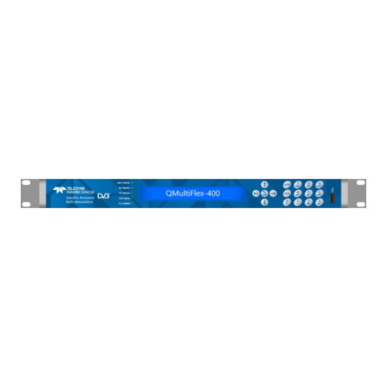
QMultiFlex-400™ Installation and Operating Handbook 5.5 Front Panel Satellite Modulator Multi-demodulator Figure 5-1 Front Panel The front panel, shown in Figure 5-1, comprises: • Light Emitting Diodes (LEDs) that provide basic modem status. • A Liquid Crystal Display (LCD) that acts as the local user interface. -
Page 22: Lcd Display
QMultiFlex-400™ Installation and Operating Handbook 5.5.2 LCD Display The backlit LCD is a graphical display formatted to give three lines of 40 text characters and is highly legible even in strong ambient light. The contrast is adjustable and the backlight can be dimmed or brightened as required. - Page 23 QMultiFlex-400™ Installation and Operating Handbook Chassis Ground Stud There is an M4 stud for connecting a safety earth conductor directly to the chassis of the unit. • Alarms and AGC Connector This is a 15-pin D-Sub high-density (HD15) plug/male pins connector that provides access to four ‘form-C’...
- Page 24 • Terrestrial Interface Positions With the QMultiFlex-400™ an ethernet processing card is installed as standard. The other interface slot is not currently used. The connections are shown below. A short Ethernet cable (shown in orange) is required to connect the IP processing card and the base Modem.
- Page 25 QMultiFlex-400™ Installation and Operating Handbook • Rx IF/L-Band Input This is a 50Ω N-Type socket/female connector. The frequency band can be selected either IF 70MHz/140MHz or L-Band. The carrier signal level at the input of the modem must be in the following range:...
-
Page 26: Chapter 6 User Interfaces
QMultiFlex-400™ Installation and Operating Handbook Chapter 6 User Interfaces 6.1 User Control The modem has both front-panel and web browser user interfaces. For remote web access, there are two fixed usernames, namely, admin and user. The admin user can view and change the modem configuration, while user can only view the modem settings. -
Page 27: Web User Interface
Edit option can be selected by simply pressing the ‘2’ key. The default IP address for all Teledyne Paradise Datacom modems is 10.0.70.1 / 16. To change M&C IP address, press: Main, 2:Edit, 3:IP, 2: Addresses - on the front panel of the Q-MultiFlex-400™. - Page 28 QMultiFlex-400™ Installation and Operating Handbook In a web browser type in the modem M&C IP address into the address bar. The browser will then request a username and password (as shown in Figure 6-1). Default credentials are: Username: admin (or user for view only)
-
Page 29: Status Screen
QMultiFlex-400™ Installation and Operating Handbook 6.2.2 Status Screen The first screen you will see, once passed the welcome screen, is the truncated status screen (Figure 6-3). To keep screens uncluttered an accordion panel system is provided to hide unwanted information. The default for these panels is closed, so it is often necessary to open them. - Page 30 QMultiFlex-400™ Installation and Operating Handbook Figure 6-4 Expanded Status Screen The line of buttons across the top of the display (i.e. STATUS, EDIT, VIEW, TEST and HELP) give access to the major modem functions, while the page tabs below the buttons give access to individual menus.
-
Page 31: Setup
QMultiFlex-400™ Installation and Operating Handbook Figure 6-5 Unit Summary Status Summary status information for the modem is shown at the top left-hand side of the screen as shown in Figure 6-5. This presents the following: • ‘ID’: The user-entered modem-identification text string – default is ‘QMultiFlex- 400™’... -
Page 32: Status
IP1 = Main traffic port connected to IP processing card IP4 (should always be up if patch cable is connected to IP processing card) IP2 = Cascade port 1. Status is up if connected to another QMultiFlex-400™ cascade port. IP3 = Cascade port 2. Status is up if connected to another QMultiFlex-400™ cascade port. -
Page 33: Status Demodulators Tab
QMultiFlex-400™ Installation and Operating Handbook Note: There is no status for Network traffic port (IP1) on IP processing card on the web GUI, but the physical port will have a green link light when active. The red/green indicators are controlled by the ethernet alarm settings. They are off by default. -
Page 34: Status Buc/Lnb Tab
QMultiFlex-400™ Installation and Operating Handbook • Transmit data rate. This is the instantaneous transmit data rate, which varies with MODCOD (MODCOD is the shorthand term used to describe the combination of modulation and FEC code rate). • Transmit MODCOD. This is the current transmit modulation and FEC rate, which vary with remote Es/No. -
Page 35: Edit Screen
QMultiFlex-400™ Installation and Operating Handbook 6.2.3 Edit Screen Figure 6-10 Edit tabs The Edit screen contains the following tab menu options: • Service. These menus allow setup of the modem transmit and receive paths plus BUC & LNB. • Unit. These menus contain all the general modem configuration settings including monitor and control, alarms, Carrier ID, Software Activated Features (SAF) and RTC time settings. -
Page 36: Edit->Service->General Screen
Figure 6-11 Edit->Service->General Screen Note: All QMultiFlex-400™ units are shipped with the hardware to support up to 16 Demodulators. Upgrades can be applied to modem in steps of 4x demodulators i.e. 4,8,12 and 16. Demod tabs will change accordingly. -
Page 37: Network Topology
QMultiFlex-400™ Installation and Operating Handbook 6.2.4.1 Network Topology Table 6-1 shows the Network topology options. Mesh Mesh mode supports direct site-to-site communications. DVB-S2/S2X inbound and outbounds are used as standard. Star Star mode supports hub and spoke communications. DVB-S2/S2X inbound and outbounds are used as standard. -
Page 38: Tx Symbol Rate
QMultiFlex-400™ Installation and Operating Handbook 6.2.4.4 Tx Symbol Rate Range: 0.1 Msps to 69.9 Msps; step size: 0.000001Msps (i.e. 1sps) Description: As an alternative to setting the terrestrial data rate, it is possible to set the symbol rate for the satellite link, which will then determine the data rate. -
Page 39: Tx Modulation
QMultiFlex-400™ Installation and Operating Handbook 6.2.4.7 Tx Modulation The supported combinations of MODCOD are listed in Table 6-6. 6.2.4.8 Tx FEC Code Rate The code rates that are available depend on the modulation selected, the frame size and DVBS2 mode. Note: DVBS2X mode includes all the DVBS2 rates. -
Page 40: Tx Frame Size
QMultiFlex-400™ Installation and Operating Handbook 6.2.4.10 Tx Frame Size Short This represents a frame size of 16,200 bits per frame. Normal This represents a frame size of 64,800 bits per frame. This is more bandwidth efficient than short frames but has four times the latency. -
Page 41: If/L-Band Output Power
QMultiFlex-400™ Installation and Operating Handbook Range: 0.0GHz to 99.999GHz; step size: 0.0000001GHz (i.e. 100Hz) Description: This is the BUC frequency used to transmit to satellite. Table 6-11 BUC Carrier Frequency 6.2.4.13 IF/L-band Output Power Range: 0.0dBm to -25.0dBm; step size: 0.1dBm Description: This sets the transmitted output power when using IF. -
Page 42: Buc Carrier
QMultiFlex-400™ Installation and Operating Handbook 6.2.4.17 BUC Carrier This allows the BUC carrier to be switched on/off. BUC carrier control requires an FSK control channel to exist between the modem and the BUC. 6.2.4.18 Rx Frequency Band The modem supports independent selection of IF and L-band operation in transmit and receive. -
Page 43: Edit->Service->General->Tx Qos Screen
Traffic shaping works by recognising markings (such as VLAN IDs) in the terrestrial packets coming into the QMultiFlex-400™ for transmission. The markings may be in the Ethernet frame or the IP header and therefore both Layer 2 and Layer 3 traffic shaping is supported. -
Page 44: Primary Qos Method
QMultiFlex-400™ Installation and Operating Handbook 6.2.5.1 Primary QoS Method This switches traffic shaping off. When off, incoming packets are buffered and transmitted on a first-come-first-served basis. Arriving packets will be dropped when the buffers are full. VLAN ID Traffic shaping is based on VLAN ID. -
Page 45: Screens For Primary Qos: Vlan Id
Figure 6-13 Edit->Service->General->Tx QoS Screen Primary QoS Method VLAN ID (Single Stream) Using VLANs with Cascaded QMultiFlex-400™ Units Multiple QMultiFlex-400™ units can be cascaded together in order to transmit a single outbound carrier to an arbitrarily large number of remote modems. -
Page 46: Stream Cir, Bir And Cir/Bir Data Rates
QMultiFlex-400™ Installation and Operating Handbook For multiple streams, with the primary QoS method set to VLAN ID, the screen shown in Figure 6-14 will be displayed. Note the extra Stream ID column. Figure 6-14 Edit->Service->General->Tx QoS Screen for Primary QoS: VLAN ID (Multiple Tx Streams) 6.2.5.4 Stream CIR, BIR and CIR/BIR Data Rates... -
Page 47: Edit->Service->General->Modcods Screen
QMultiFlex-400™ Installation and Operating Handbook 6.2.6 Edit->Service->General->MODCODs Screen The Edit->Service->General->MODCODs screen is shown in Figure 6-15. Figure 6-15 Edit->Service->General->MODCODs Screen When multiple streams are enabled, each stream is associated with its own MODCOD. All packets that have the specified VLAN ID will be placed into the stream. A stream will be accorded the bandwidth defined by the CIR and BIR values set in the QoS rules table. -
Page 48: Stream Enable
QMultiFlex-400™ Installation and Operating Handbook 6.2.6.1 Stream Enable This is an On/Off control that controls whether a particular stream forms part of the shared outbound or not. When enabled, all packets associated with the relevant stream will form part of the shared outbound. -
Page 49: Screens For Primary Qos: Ip Address
QMultiFlex-400™ Installation and Operating Handbook 6.2.6.6 Screens for Primary QoS: IP Address When the primary QoS method is set to IP address then the screen shown in Figure 6-16 will be displayed when using a single stream (i.e. a single MODCOD is being used for the shared outbound). - Page 50 QMultiFlex-400™ Installation and Operating Handbook Figure 6-17 Edit->Service->General->Tx QoS Screen for Primary QoS: IP Address (Multiple Streams) The number of available streams is determined by the number of streams that are enabled. Figure 6-18 Edit->Service->General->MODCODs Screen for Primary QoS: IP Address (Multiple Streams) – Stream MODCOD Entry...
-
Page 51: Screen For Primary Qos: Diffserv
QMultiFlex-400™ Installation and Operating Handbook Figure 6-19 Edit->Service->General->Tx QoS Screen for Primary QoS: IP Address (Multiple Streams) – QoS Rule Entry Any combination of source/destination addresses and a range of ports can be used to define the packets that will be governed by each QoS rule. For each QoS rule, the bandwidth to be made available is defined by the CIR and BIR values. - Page 52 QMultiFlex-400™ Installation and Operating Handbook Figure 6-20 Edit->Service->General->Tx QoS Screen for Primary QoS: Diffserv (Single Stream) The standard Diffserv classes are listed in the left-hand column. A default rule is available to explicitly reserve bandwidth for non-Diffserv packets. 6.2.6.8 Screen for Primary QoS: IEEE 802.1p When the primary QoS method is set to IEEE 802.1p then the screen shown in Figure 6-21...
-
Page 53: Edit->Service->Demods Screen
QMultiFlex-400™ Installation and Operating Handbook Figure 6-21 Edit->Service->General->Tx QoS Screen for Primary QoS: IEEE 802.1p (Single Stream) The IEEE 802.1p priority classes (part of the IEEE 802.1Q header) are represented as 0 to 7 in the left-hand column. For each QoS rule, the bandwidth to be made available is defined by the CIR and BIR values. -
Page 54: Rx Carrier Frequency
QMultiFlex-400™ Installation and Operating Handbook Figure 6-22 Edit->Service->Demods Screen 6.2.7.1 Rx Carrier Frequency There are various frequency control options, depending on whether IF or L-band has been selected and whether an LNB is connected and being controlled by the modem. The frequency control options are presented in Tables 6-19 through 6-21. -
Page 55: Rx Symbol Rate
QMultiFlex-400™ Installation and Operating Handbook Range: 0.0GHz to 99.999GHz; step size: 0.0000001GHz (i.e. 100Hz) Description: This is the LNB frequency used to receive from satellite. If the LNB LO frequency has been set on the Edit->Service->LNB menu then the L-band receive frequencies used by the individual demodulators will no longer be available and will be replaced with an LNB carrier frequency. -
Page 56: Buc Interface
QMultiFlex-400™ Installation and Operating Handbook 6.2.8.1 BUC Interface BUC FSK This indicates that a BUC is fitted that has FSK communications to the modem. This indicates that a BUC is fitted but has no communications to the comms modem. No BUC This indicates that no BUC is connected. -
Page 57: Edit->Service->Lnb Screen
QMultiFlex-400™ Installation and Operating Handbook 6.2.9 Edit->Service->LNB Screen The Edit->Service->LNB screen is shown in Figure 6-24. Figure 6-24 Edit->Service->LNB Screen 6.2.9.1 LNB Type None This indicates that no LNB is connected. Other This indicates that an LNB is connected but is not one of the LNBs listed below. -
Page 58: Mute Lnb Services In Standby
QMultiFlex-400™ Installation and Operating Handbook 6.2.9.5 Mute LNB Services in Standby This is an On/Off control used to enable and disable the transfer of LNB DC and 10MHz services from a failed modem to a backup modem in a 1:1 or 1:N redundancy system. -
Page 59: Modem Control And Passwords
QMultiFlex-400™ Installation and Operating Handbook 6.2.11.1 Modem Control and Passwords Local In Local mode only the front panel can be used to control the modem. Local+remote In Local+remote mode, the modem accepts commands from any user interface at any time. -
Page 60: Radius Authentication Validity
This involves the addition of a vendor-specific attribute using an SMI network management private enterprise code of 64534 (to denote Teledyne Paradise Datacom), which is one of a range reserved for private use. A vendor-specific attribute named ‘Access-Level’... -
Page 61: Modem Identity
It should be noted that the Q-NET Navigator control application (which can be downloaded freely from the Teledyne Paradise Datacom web site) has the ability to configure hub and remote modems without the user having to be concerned with how the changes are synchronised between the modems, thereby removing this problem entirely. -
Page 62: Edit->Unit->M&C-> Snmp Screen
QMultiFlex-400™ Installation and Operating Handbook 6.2.12 Edit->Unit->M&C-> SNMP Screen The Edit->Unit->M&C->SNMP screen is shown in Figure 6-27. Figure 6-27 Edit->Unit->M&C->SNMP Screen The Simple Network Management Protocol (SNMP) can be configured for use with SNMP v1, v2c and v3. The modem’s SNMP configuration settings have the standard meanings defined by the relevant SNMP standards and are therefore not described in detail. - Page 63 QMultiFlex-400™ Installation and Operating Handbook Figure 6-28 Edit->Unit->M&C->Email Screen From power-up, the modem automatically records modem and satellite link performance information for both online and offline use. This information can be sent by email from the modem to any email address, providing a connection from the modem to an available Simple Mail Transfer Protocol (SMTP) mail server.
-
Page 64: Edit->Unit->M&C->Https Screen
QMultiFlex-400™ Installation and Operating Handbook The following example demonstrates how to graph modem constellation data in a spreadsheet: • Configure the SMTP mail server and recipient email details. • Select the Constellation data check box and click the Send email now button. -
Page 65: Edit->Unit->Alarms Screen
QMultiFlex-400™ Installation and Operating Handbook Figure 6-30 Edit->Unit->M&C->HTTPS Screen Secure HTTPS connections to the modem’s web server (on port 443) are always enabled. However, it is possible to disable (and re-enable) standard HTTP requests (on port 80) using this screen. -
Page 66: Lnb Dc Current Alarm
QMultiFlex-400™ Installation and Operating Handbook Range: 0.1A to 6.0A; step size: 0.01A (i.e. 10mA) Description: Sets the trip threshold at which a fault is declared when the current drawn by the Tx ODU is outside the limit. Both a minimum and a maximum current threshold can be set. - Page 67 SAF features. Any remaining time of the test period is lost. The New SAF code edit box is used to enter a code provided by Teledyne Paradise Datacom that unlocks additional modem features. When unlocked, the features immediately become available.
-
Page 68: Edit->Unit->Upgrade Screen
QMultiFlex-400™ Installation and Operating Handbook 6.2.17 Edit->Unit->Upgrade Screen Upgrade from web user interface The Edit->Unit->Upgrade screen is shown in Figure 6-33. This allows the modem’s software to be upgraded (and downgraded). This can also be done via the front-panel menus and a USB memory stick. - Page 69 QMultiFlex-400™ Installation and Operating Handbook Simply drag and drop the upgrade zip file into the ‘Drag & Drop files here’ section of the box, or use the ‘Click to open the file Browser’ button to search for the upgrade file. The modem should then upload the file.
- Page 70 QMultiFlex-400™ Installation and Operating Handbook Figure 6-36 Edit->Unit->Upgrade Screen Progress Indication A remote modem can be upgraded over the satellite link by browsing to the remote modem’s IP address and following the same upgrade process. Note that the speed of the upgrade is dependent on the bandwidth available over satellite.
-
Page 71: Edit->Unit->Miscellaneous->Time Screen
QMultiFlex-400™ Installation and Operating Handbook Upgrade from USB memory stick • Create a new folder on the USB memory stick and name it `upgrade`. • Unzip the contents of the software upgrade zip file ‘QMulti-400-3.x.xx.zip’ to this folder. • If there is a file called ‘preupgrade.sh’ then delete this from the upgrade folder. -
Page 72: Edit->Unit->Miscellaneous->Reset Screen
QMultiFlex-400™ Installation and Operating Handbook Figure 6-38 Edit->Unit->Miscellaneous->Time Screen 6.2.19 Edit->Unit->Miscellaneous->Reset Screen The Edit->Unit->Miscellaneous->Reset screen is shown in Figure 6-39. Clicking the ‘Reset modem’ button allows the modem to be reset, following confirmation. Figure 6-39 Edit->Unit->Miscellaneous->Reset Screen 6.2.20 Edit->Unit->Miscellaneous->NTP Screen The Edit->Unit->Miscellaneous->NTP screen is shown in Figure 6-40. -
Page 73: Edit->Unit->Carrier Id Screen
QMultiFlex-400™ Installation and Operating Handbook The modem will request the current time from the NTP server on a regular basis. A time offset can be applied to the modem to account for any regional deviation from UTC. Figure 6-40 Edit->Unit->Miscellaneous->NTP Screen 6.2.21... -
Page 74: Carrier Id Latitude And Longitude
QMultiFlex-400™ Installation and Operating Handbook 6.2.21.2 Carrier ID Latitude and Longitude The Carrier ID Latitude and Longitude fields allow the user to enter the geographic position of the modem. This information is transmitted as part of the Carrier ID and allows a Carrier ID decoder to identify the location from which an interfering carrier is being generated. -
Page 75: Edit->Ip Screen
QMultiFlex-400™ Installation and Operating Handbook 6.2.22 Edit->IP Screen The Edit->IP screen (shown in Figure 6-42) allows the following to be configured: • Basic and advanced IP modes and features, such as bridging, routing, acceleration and ACM. • The modem’s terrestrial and satellite traffic IP addresses. -
Page 76: Ip Mode
The default for this setting is ‘On’ (for historical reasons). This will need to be turned ‘Off’ for normal operation. Never operate the QMultiFlex-400™ in a network with the M&C bridge tuned On (default setting). Figure 6-43 shows the check box unchecked. -
Page 77: Tcp Acceleration
QMultiFlex-400™ Installation and Operating Handbook 6.2.22.3 TCP Acceleration This is an On/Off control that controls point-to-multipoint TCP acceleration. Packets received by the modem will be either bridged or routed as determined by the IP mode setting. When on, TCP packets are processed by a Performance Enhancing Proxy (PEP) that overcomes performance problems associated with using standard TCP over satellite. -
Page 78: Acm Mode
MODCOD to suit the current conditions. Carrier symbol rate and power remain unchanged, but data rate will vary with the choice of MODCOD. With many remotes reporting their Es/No back, the QMultiFlex-400™ will always act upon the lowest Es/No. Monitor ACM data is sent and received, but no action is taken to change the transmitting MODCOD. -
Page 79: M&C Ip Address, Subnet Mask & Modem Ip Gateway
QMultiFlex-400™ Installation and Operating Handbook 6.2.22.9 M&C IP Address, Subnet Mask & Modem IP Gateway M&C IP Address 10.0.70.1 Default: Description: This sets the IP address for remote control. An IP address of 0.0.0.0 causes the modem to request its IP... -
Page 80: M&C And Ip Traffic Ethernet Speed/Duplex
QMultiFlex-400™ Installation and Operating Handbook Traffic 255.255.255.0 subnet mask default: This sets the subnet mask for the modem’s IP Traffic port. Description: Satellite 0.0.0.0 (only available in routing mode) IP address default: This sets the IP address for the modem’s satellite IP port. This is... -
Page 81: Ipv4/Ipv6 Mode
QMultiFlex-400™ Installation and Operating Handbook 1000M half-duplex The modem will auto-negotiate the Ethernet speed and duplex settings but as part of the negotiation will ‘advertise’ 1000Mbps half-duplex as the only option available. 1000M full duplex The modem will auto-negotiate the Ethernet speed and duplex settings but as part of the negotiation will ‘advertise’... -
Page 82: Ethernet Mtu
QMultiFlex-400™ Installation and Operating Handbook 6.2.22.13 Ethernet MTU Range: 1,000 bytes to 10,240 bytes; step size: 1 byte (Default 1500) Description: This controls the Ethernet Maximum Transmission Unit (MTU) size, which defines the largest Ethernet frame that can be handled by the modem in bridging mode without fragmentation into smaller frames. -
Page 83: Satellite Buffer Size
QMultiFlex-400™ Installation and Operating Handbook 6.2.22.16 Satellite Buffer Size Range: 1 to 256 packets (Default 256) Description: The satellite buffer is used to buffer IP packets ready for transmission over satellite. The buffer is situated after all internal packet processing has been completed, including traffic shaping and encapsulation. -
Page 84: Ethernet Address Learning
QMultiFlex-400™ Installation and Operating Handbook Active Queue Management continually measures the packet delay through the modem and rather than let the backlog of packets build up, it ensures that the delay through the modem is kept constant by dropping packets early if required. (The modem implements a form of active queue management called CoDel, which stands for Constant Delay. -
Page 85: Secondary M&C Vlan Id
QMultiFlex-400™ Installation and Operating Handbook 6.2.22.21 Secondary M&C VLAN ID Range -1 to 4095 (default is -1 disabled). Description: This secondary M&C VLAN is only used when migrating a VLAN ID to a different number within a system. The idea is to use the desired VLAN ID as the main VLAN ID. -
Page 86: Enable Vlan Filtering / Vlan Id
QMultiFlex-400™ Installation and Operating Handbook 6.2.22.25 Enable VLAN filtering / VLAN ID This control is used exclusively for mesh mode operation. See separate document: AN_057 P2MP Mesh Network Routing Mode Configuration Notes available from technical support. 6.2.22.26 Remote to Remote Comms This is an On/Off control that controls whether traffic received from a remote modem is retransmitted over satellite to the other remote modems. -
Page 87: Edit->Paired Carrier Screen
QMultiFlex-400™ Installation and Operating Handbook The Click to apply routes button must be selected to apply the static routes before navigating away from the web page. The Show Routes button can be used to display the underlying operating system ‘route add’... -
Page 88: Round-Trip Delay
QMultiFlex-400™ Installation and Operating Handbook 6.2.24.2 Round-trip Delay The modem needs to know the delay to the satellite in order for Paired Carrier to work. The following table shows the supported methods of delay entry. Set location The modem automatically calculates the satellite round trip delay using the decimal latitude / longitude coordinates that are entered for the modem location and the satellite longitude. -
Page 89: Earth Station Latitude
QMultiFlex-400™ Installation and Operating Handbook 6.2.24.5 Earth Station Latitude Range -90 Degrees to +90 Degrees; step size: 0.01 Degrees Description: The latitudinal position corresponding to the modem location. A positive number indicates North and a minus sign can be used to indicate South of the equator. -
Page 90: Rx Carrier Frequency
QMultiFlex-400™ Installation and Operating Handbook 6.2.24.9 Rx carrier frequency Range IF: 50MHz to 180MHz; Step: 0.0001 MHz (100Hz) L-Band: 950MHz to 2450MHz; Step: 0.0001 (100Hz) This is the frequency used to cancel out the ‘echo’ of the outgoing carrier. Description: Ascertain the centre frequency of the returned echo and enter this in the Rx Carrier Frequency field. -
Page 91: Edit->Memories->Recall Screen
QMultiFlex-400™ Installation and Operating Handbook Configuration memory names are restricted to alphanumeric characters. Figure 6-47 Edit->Memories Screen 6.2.25.1 Edit->Memories->Recall Screen The Edit->Memories->Recall screen (shown in Figure 6-48) displays all of the configuration memories that are stored on the modem. A specific configuration memory can be made active by selecting the associated Recall button. - Page 92 QMultiFlex-400™ Installation and Operating Handbook Figure 6-49 Edit->Memories->Advanced Reversionary Control Screen The procedure for protecting and recovering a remote modem from failure during a configuration change is as follows. 1. Prepare in advance a configuration memory that represents a known ‘safe’ or default configuration for the remote modem.
-
Page 93: Edit->Memories->Store Screen
QMultiFlex-400™ Installation and Operating Handbook Figure 6-50 Edit->Memories->Advanced Reversionary Control Screen (Active state) 6.2.25.3 Edit->Memories->Store Screen The Edit->Memories->Store screen (shown in Figure 6-51) allows the current modem configuration to be stored to a configuration memory under a given name. It also displays all the configurations that are already stored on the modem. -
Page 94: Edit->Memories->Upload Screen
QMultiFlex-400™ Installation and Operating Handbook Figure 6-52 Edit->Memories->Download Screen 6.2.25.5 Edit->Memories->Upload Screen The Edit->Memories->Upload screen (shown in Figure 6-53) allows the user to browse to a location on their file system where they have a configuration memory file that they want to upload to the modem. - Page 95 QMultiFlex-400™ Installation and Operating Handbook Figure 6-54 Edit->Redundancy->1-for-1 Screen The Redundancy status shows the 1:1 status of the modem. This will be shown as Main when the modem is online, Maintenance when the modem has been taken out of service, and Standby when the modem is offline, ready to switch over on a fault occurring on the online modem.
-
Page 96: Edit->Redundancy Screen - Geographical Redundancy
QMultiFlex-400™ Installation and Operating Handbook Once the modem is in Maintenance mode, the Switch to maintenance button is replaced with a Switch to service button, which can be used to reverse the process by making the modem available to come online. - Page 97 QMultiFlex-400™ Installation and Operating Handbook Monitor demod: Defines which demodulator will be used to detect if the hub outbound carrier has a problem. Since monitoring a demod is a mandatory requirement for Geo Redundancy to work, it is worth noting that a single demod is limited to 40Msps, thus this limits the out-bound carrier to 40Msps.
-
Page 98: View Screen
QMultiFlex-400™ Installation and Operating Handbook 6.2.27 View Screen Figure 6-57 View Screen The View screen allows the following to be viewed: • Graphs. These include spectrum, constellation, IP throughput and time-based performance graphs. None of these interfere with the service being provided by the modem. - Page 99 QMultiFlex-400™ Installation and Operating Handbook Figure 6-58 Rx Spectrum Monitor The Rx Spectrum Monitor can be used to check for correct modem operation. Each demodulator can be viewed individually or a wideband (Super Wide) mode can be selected that shows a 72MHz span of the transponder centred on the inbound carrier centre frequency (subject to the position of the carrier within the 72MHz span of the modem receiver front end).
-
Page 100: View->Graphs->Constellation; Rx Constellation Monitor
QMultiFlex-400™ Installation and Operating Handbook 6.2.27.2 View->Graphs->Constellation; Rx Constellation Monitor The Rx Constellation Monitor feature shown in Figure 6-59 allows the modem to be used as an oscilloscope in X/Y mode to view the constellation. Figure 6-59 Rx Constellation Monitor The Rx Constellation Monitor can be used to check for correct modem operation including checking for signal distortion and phase noise. - Page 101 QMultiFlex-400™ Installation and Operating Handbook They are defined as follows: • MER (dB) = Power of ideal signal Power of error signal • EVM (%) = Power of error signal Power of ideal signal A high MER and low EVM indicate a good signal, whereas a low MER and a high EVM indicate a poor quality signal.
-
Page 102: View->Graphs->Ip Graphs
QMultiFlex-400™ Installation and Operating Handbook where MER=28.0dB and EVM=4.0%. The following is an example of a worse signal (close to QEF limit): where MER=10.7dB and EVM=29.2%. 6.2.27.3 View->Graphs->IP Graphs Figure 6-60 shows an example of an IP throughput graph. IP graphs support the display of throughput (including errored and dropped packets) for transmit and receive in bits per second and packets per second for the terrestrial and satellite ports. - Page 103 QMultiFlex-400™ Installation and Operating Handbook Figure 6-60 IP Throughput Graph – Satellite Traffic View An example ACM graph is shown in Figure 6-61. This shows the minimum, average and maximum terrestrial data rate over the selected time period. Note that this graph shows how the terrestrial data rate varies over time in direct relation to dynamic changes of MODCOD based on a varying Es/No from the remote modem.
- Page 104 QMultiFlex-400™ Installation and Operating Handbook Figure 6-61 ACM Terrestrial Data Rate Graph Other ACM graphs are available, such as the remote Es/No graph shown in Figure 6-62, which shows the worst remote Es/No that ACM was using to make MODCOD selections.
-
Page 105: View->Graphs->Ip->Qos; Stream Graphs
MODCOD is normally gained through link budget analysis. Figure 6-63 ACM Utilisation graph Note: The ACM Availability graph is not applicable for the QMultiFlex-400™ but is available in the remote modems to analyse the hub modems demodulator lock status. 6.2.27.4 View->Graphs->IP->QoS; Stream Graphs Graphs of the Tx QoS stream throughputs over time are available (Bits per second). -
Page 106: View->Graphs->Others; Other Time-Based Graphs
QMultiFlex-400™ Installation and Operating Handbook Figure 6-64 Tx QoS Stream Throughput Graph 6.2.27.5 View->Graphs->Others; Other Time-based Graphs A number of time-based graphs can be displayed. Graphical values are stored for 31 calendar days or until the modem is powered down. The recording of all values occurs automatically at all times once the modem is powered on and is not dependent on whether the graphs are being viewed or not. -
Page 107: View->Alarms Screen
QMultiFlex-400™ Installation and Operating Handbook Figure 6-65 Temperature Graph – Hour Span 6.2.27.6 View->Alarms Screen System alarms can be viewed using the View->Alarms screen shown in Figure 6-66. Alarms are latched and their status will be shown as Off if they are no longer active. The Accept button can be used to delete all the alarms after which the web page will automatically update and show details of any alarms that are still active. -
Page 108: View->System Log
QMultiFlex-400™ Installation and Operating Handbook 6.2.27.7 View->System Log The system log can be viewed using the View->Log screen shown in Figure 6-67. The Clear button can be used to delete all of the entries in the log. The Download Log file button can be used to download a text file of the log contents to the browser device. -
Page 109: View->Unit Screen
QMultiFlex-400™ Installation and Operating Handbook 6.2.27.9 View->Unit Screen The View->Unit screen shown in Figure 6-69 displays manufacturing information (including the software version number and the hardware fitted), power supply voltage levels, modem temperature indication, and the IP address of the M&C port, which can be useful if DHCP was used to acquire the address. -
Page 110: View->Tx Qos Screen
QMultiFlex-400™ Installation and Operating Handbook Figure 6-70 View->SAF Screen 6.2.27.11 View->Tx QoS Screen The View->Tx QoS screen shown in Figure 6-71 displays metrics for the shared outbound carrier in terms of total stream throughput, including dropped packet counts and current stream data rates (in packets per second and bits per second). -
Page 111: Test Screen
QMultiFlex-400™ Installation and Operating Handbook Figure 6-72 shows the metrics collected for specific classes. Figure 6-72 View->Tx QoS Class Screen 6.2.28 Test Screen The Test screens support the following test functions: • RF Test Modes. This provides two types of signal – a CW (pure carrier) signal and an alternate 1,0 signal that can be used to test modem carrier operation. -
Page 112: Modulator Alternate 1,0
QMultiFlex-400™ Installation and Operating Handbook 6.2.28.2 Modulator alternate 1,0 With this enabled - an alternating 1,0,1,0 pattern is fed to the modulator at the selected symbol rate. This causes two discrete frequencies to be generated, spaced at the symbol rate about the center frequency (suppressed carrier). This is useful for evaluating the carrier suppression of the modulator but should not be used over a live satellite link. -
Page 113: Front-Panel Interface
QMultiFlex-400™ Installation and Operating Handbook 6.3 Front-panel Interface 6.3.1 Keypad Operation 6.3.1.1 Cursor An inverse-video cursor is used to navigate around the LCD display. See Figure 6-74 for an example. ‘2:Edit’ is being highlighted by the cursor. [QMultiFlex-400] 1:Status 2:Edit... -
Page 114: Alphanumeric Keys
QMultiFlex-400™ Installation and Operating Handbook MAIN Key The MAIN key returns the user to the MAIN menu from anywhere in the menu hierarchy. ENTER Key On a menu, the ENTER key is used to navigate to the submenu highlighted by the cursor. -
Page 115: Lcd Screen Layout
QMultiFlex-400™ Installation and Operating Handbook Log/Alarm Clear The system log and system alarms can be cleared by pressing the 0 key when on the front- panel View->Log and View->Alarms screens. 6.3.2 LCD Screen Layout The front panel user interface uses a menu system to present choices to the user. These in turn allow either the selection of a value from a list of options or require the setting of a new value. -
Page 116: Extracting Configurations To Usb Drive - Via The Front Panel
QMultiFlex-400™ Installation and Operating Handbook View Displays detailed operational status and read-only configurable property values. Test Controls the selection of test modes. Please refer to the equivalent web user interface menus for further information on the front-panel menu options. Note that complex, advanced features of the web user interface such as graphs, static routes and traffic shaping are not supported via the front panel. -
Page 117: Uploading Configuration Files To Modem - Via The Front Panel
QMultiFlex-400™ Installation and Operating Handbook 6.3.5 Uploading Configuration files to Modem - Via the Front Panel With a USB drive inserted into the front of the modem, navigate to the memory screen. Main, Edit, Memories. 1:Store 2:Recall 3:Erase 4:Save to USB 5:Load USB Press ‘Load USB’... -
Page 118: Chapter 7 Q-Net™ Implementation
QMultiFlex-400™ Installation and Operating Handbook Chapter 7 Q-NET™ Implementation This section shows some topologies used with Q-NET™ networks and includes some information to help implement a Q-NET™ system. The Q-NET™ satellite network solution is a highly flexible and scalable satellite network solution designed for a broad range of markets, applications and business models. -
Page 119: Network Topologies
Point-to-Multipoint Star Network A star network topology is shown in Figure 7-1. In this scenario, a QMultiFlex-400™ generates a shared outbound from the hub to the remotes, which have QFlex-400™ modems for receiving the outbound. They generate return carriers back to the hub, which are demodulated by the QMultiFlex-400™. The box count starts at literally one box at the hub and one at each site for the smallest network. -
Page 120: Mesh Network
A mesh network topology is shown in Figure 7-2. In a mesh network there is no hub and therefore remote-to-remote communications are all single hop. In the simplest case each site has a single QMultiFlex-400™. In a full mesh each site transmits an outbound to every site and receives a carrier from every other site. -
Page 121: Point-To-Point Network
QMultiFlex-400™ Installation and Operating Handbook 7.1.3 Point-to-point Network A point-to-point network topology is shown in Figure 7-3. This type of network consists of a series of individual point-to-point links between QFlex-400™ modems. As well as dedicated point-to-point networks, point-to-point links are often used for occasional-use links in larger point-to-multipoint networks or to address parts of the network that require limited connectivity. -
Page 122: Tcp/Ip Traffic Management
Figure 7-4 shows the most basic configuration used for a point-to-multipoint bridging solution. Ethernet switches can be deployed, as required, between the satellite devices (QMultiFlex-400™, QFlex-400™) and the user network (the user network being any combination of switches, routers and end-user devices). In this scenario, a single subnet is used for the satellite modem network. -
Page 123: Point-To-Multipoint Routing
7.2.2 Point-to-Multipoint Routing In routing mode, the QMultiFlex-400™ and QFlex-400™ modems act as two-port routers, with the terrestrial IP port being on one subnet and the satellite port being on another subnet. (The M&C network can be on yet another subnet.) The satellite ports of all QMultiFlex-400™... - Page 124 In Figure 7-5, arbitrarily complex networks (potentially with multiple subnets) exist attached to routers on both sides of the satellite network. The QMultiFlex-400™ is configured for a unique subnet that it shares with its local router. A single subnet is used over satellite to connect the satellite ports of the QMultiFlex-400™...
-
Page 125: Cascading Multiple Qmultiflex-400™ Units
QMultiFlex-400™ Installation and Operating Handbook 7.3 Cascading Multiple QMultiFlex-400™ Units Multiple QMultiFlex-400™ units can be cascaded together in order to address an arbitrarily large number of remote modems with a single outbound carrier. There are two methods that can be used to cascade units together. The first involves cascading units directly together and involves no external equipment. - Page 126 QMultiFlex-400™ Installation and Operating Handbook Figure 7-7 Cascaded Q-MultiFlex-400™ Units (for up to 80 remotes per shared outbound)
-
Page 127: Modem Redundancy Protection
64 remote sites are protected by a single backup unit. A PDQS redundancy switch (and backup QMultiFlex-400™) is used to protect four QMultiFlex-400™. Figure 7-8 QMultiFlex-400™ 1:4 Redundancy Setup (64 remotes sharing single outbound) However, users may want to consider independent protection for the hub Tx and Rx... - Page 128 QMultiFlex-400™ Installation and Operating Handbook Figure 7-9 Separate Tx (1:1) and Rx (1:N) Redundancy Setup 7-11...
-
Page 129: Remote Modem M&C
QMultiFlex-400™ Installation and Operating Handbook 7.5 Remote Modem M&C It is not recommended to use the M&C bridge to bridge M&C and IP traffic together as typically there are separate VLANS involved using different networks. Bridging the M&C and traffic together limits the unit to one network, which is not typically what is desired with a point to multipoint network. -
Page 130: Multiple Streams And Traffic Shaping
QMultiFlex-400™ Installation and Operating Handbook 7.6 Multiple Streams and Traffic Shaping Single stream mode allows a single MODCOD to be applied to the shared outbound carrier, whereas with multiple streams, potentially different MODCODs can be applied to the individual streams when they are transmitted over satellite in the shared outbound carrier (a feature known as Variable Coding and Modulation (VCM)). - Page 131 QMultiFlex-400™ Installation and Operating Handbook stream) in the shared outbound with varying link conditions as experienced by each remote modem. ACM therefore converts any unused link margin (on a per-site basis) into additional throughput. ACM also provides 100% link availability by allowing the use, during heavy rain fades, of MODCODs with very high error-correcting ability (down to QPSK ¼).
-
Page 132: Chapter 8 System Considerations
QMultiFlex-400™ Installation and Operating Handbook Chapter 8 System Considerations 8.1 Automatic Uplink Power Control Authorisation from the satellite operator should be sought before AUPC is activated. 8.1.1 Introduction Automatic Uplink Power Control (AUPC) provides a mechanism to counteract changes in atmospheric conditions, such as rain or snow, that degrade the performance of satellite links. -
Page 133: Adaptive Coding & Modulation (Acm)
The web user interface remote Eb/No and power graphs can be used to review AUPC performance. Note: AUPC is limited to a single QMultiFlex-400™ unit i.e. up to 16 remotes. Cascaded units are not currently supported. There are other limitations with this feature in a Point to Multipoint system. - Page 134 The receive side is degraded, hopefully within a rain fade margin. ACM & VCM (Bidirectional ACM) Multiple Tx Streams can be configured in the QMultiFlex-400™ with the remote demod matching the MODCOD for each stream. Applying ACM will make the VCM links even more robust, with each individual stream changing to adapt to environmental conditions.
-
Page 135: Configuring Acm
QMultiFlex-400™ Installation and Operating Handbook Degradation position 2: Hub individual stream MODCOD changes and reduces throughput as necessary to maintain link (other streams stay the same). The remote transmit adjusts MODCOD to keep the respective demodulator in lock. Note: VCM can be used in the one-way outbound mode, but for maximum robustness the bi-directional ACM would be typical in a multiple stream scenario. -
Page 136: Hub Cancellation
Figure 8-5 Hub Canceller Spectra This section describes the operation and configuration of a QMultiFlex-400™ DVBS2(X) hub modem incorporating a hub canceller, operating in a star network configuration. This section will also explain the expected additional system losses, due in part, to the self- interference by the return carriers being located under the larger hub outbound carrier and ways of mitigating this additional system loss. -
Page 137: Hub Hardware Configuration
8.3.1 HUB Hardware Configuration Check within the ‘Hardware fitted’ information box (View > Unit) that the QMultiFlex-400™ series hub Modem has 2x DVB-S2X interface cards installed. With the Hub canceller enabled the unit will support up to 14 demodulators, assuming all are enabled within the... -
Page 138: Initial Configuration
QMultiFlex-400™ Installation and Operating Handbook Figure 8-7 - QMultiFlex-400™ Hub Modem Unit information Check within the feature list (View > SAF) that the QMultiFlex-400™ series hub Modem has sufficient demodulators enabled for the proposed network and that Paired Carrier™, up to the desired cancelling bit rate, is enabled. -
Page 139: Hub Modem Configuration
Demods 1 - 16 Enable / Disable Demods 1-4 & 7 Enabled Table 8-1 – Hub QMultiFlex-400™ Example Configuration Navigate to the Edit > Service > Demod 1 to 8 menu tab and configure each demodulator in turn: Heading Parameter... -
Page 140: Initial Measurements
QMultiFlex-400™ Installation and Operating Handbook Tx Rate Control Data / Symbol Rate Data Rate 120k – 60Mbps Tx Data Rate 2Mbps Tx Clock Source Internal / Tx Clk In / Rx Ref Internal Rx Service DVB-S2/X / Fastlink / Closed Net... - Page 141 Then we would configure the Hub Modem to use (140.0e6-57.329e3=) 139.942671MHz, the true center frequency of the echo signal. Figure 8-9 - QMultiFlex-400™ Rx Carrier Frequency Field On completion, restore the hub demodulator configuration and drop the hub transmit carrier.
-
Page 142: Canceller Operation
QMultiFlex-400™ Installation and Operating Handbook QFlex-400 series Remote Modem Es/No can be noted from the Status screen: Figure 8-11 – QFlex-400 Status Screen Record the measured levels within the table below to compare when the hub canceller is enabled. Remote Modem... -
Page 143: Enable Hub Outbound Carrier And Canceller
QMultiFlex-400™ Installation and Operating Handbook 8.3.4.1 Enable Hub Outbound Carrier and Canceller Enable the Hub Modem’s carrier. The remote Modem demodulators will lock, at the same time the hub multi-demodulators will unlock. Configure the Hub Canceller: Enable the Hub Canceller: (Edit > Paired Carrier) -
Page 144: Lab Configuration
QMultiFlex-400™ Installation and Operating Handbook acquisition time by setting minimum and maximum delay values based around the calculated value. It can also be compared to the actual satellite delay reported on the Status screen. 8.3.4.3 Lab Configuration If initially testing the Hub canceller in a lab environment, where the hub and remote modems are co-located, the RTD will be approximately 0 (unless a satellite delay simulator is used in the signal path) as there will be no significant delay in the echoed signal. - Page 145 QMultiFlex-400™ Installation and Operating Handbook Figure 8-13 - Hub Canceller Spectra Figure 8-14 - Hub Canceller with overspill IB carriers 8-14...
- Page 146 QMultiFlex-400™ Installation and Operating Handbook Figure 8-15 - Hub Canceller with overspill IB carriers The typical summary status page for a QMultiFlex-400™ hub modem is shown below: Figure 8-16 - Hub Canceller Metrics 8-15...
- Page 147 QMultiFlex-400™ Installation and Operating Handbook Figure 8-16 shows four Paired Carrier hub canceller monitor values: 1. Paired Carrier Lock: Shows real-time lock status. Should the canceller lose lock, an alarm will appear on the `View > Alarms` menu. The alarm will also be registered in the log file, which can be viewed by navigating to `View >...
- Page 148 QMultiFlex-400™ Installation and Operating Handbook Figure 8-18 – The Selected Zoomed Area Repeat and compare the measurements of the hub and remote Es/No metrics to those obtained prior to the canceller being enabled, as recorded in Table 8-4. Remote Modem...
- Page 149 QMultiFlex-400™ Installation and Operating Handbook Similarly, the IB carriers are viewed as being white noise contributors and therefore these interfere with the OB carrier and will degrade each remote Modem’s Rx Es/No. i.e. the remotes will see the OB carrier plus satellite channel system noise, plus self-interference from their own carriers.
-
Page 150: Troubleshooting Guide
8.3.6.1 Why Can I Not Enable the Hub Canceller? For the Hub canceller to be enabled, you need the hardware to host it. To verify you have the hardware, navigate to `View > Unit` menu screen, as follows: Figure 8-20 - QMultiFlex-400™ Hub Modem Unit information 8-19... -
Page 151: Why Does The Hub Canceller Not Lock
SAF code to run the Hub Canceller feature, navigate to View > SAF menu. An example is shown below: Figure 8-21 - QMultiFlex-400™ Hub Modem SAF information Under the Advanced Operation sub menu, check to see whether you have a Paired Carrier SAF with a green On label associated with it. -
Page 152: Why Does The Hub Canceller Lose Lock After Acquiring
QMultiFlex-400™ Installation and Operating Handbook 2. Spectral Inversions wrong There is a spectral inversion in the communications path preventing the canceller to correlate its local reference to the received echo. This is a common problem and stems from a confusion on how to correct for spectral inversions; should they be corrected in the... - Page 153 QMultiFlex-400™ Installation and Operating Handbook 2. The satellite orbit inclination is too great. Most geostationary satellites are positioned and maintained at 0° latitude to within a few tenths of a degree. Towards the end of a satellite’s operational life, the ability to maintain its position diminishes as its propellant resources decrease.
-
Page 154: Why Does The Hub Canceller Es/No Seem Unstable
QMultiFlex-400™ Installation and Operating Handbook Figure 8-23 – Cumulative Doppler Shift of Intelsat-12 As Seen from London Figure 8-22 shows the delay Doppler varying sinusoidally over the course of 24 hours (86400 seconds), as does the frequency offset Doppler in Figure 8-23. However, when the rate of change of the RTD Doppler is at a maximum in Figure 22 at t=0, the rate of change of the frequency offset Doppler is zero. -
Page 155: Why Is The Es/No Worse When The Hub Canceller Is Enabled
8.3.6.7 Hub Canceller vs No. of Rx channels All QMultiFlex-400™ hub modems are fitted with hardware to support: A) 14 Rx channels with a hub-canceller enabled or B) 16 Rx channels (an extra two Rx channels) without the hub-canceller being enabled. -
Page 156: 1:1 Redundancy Operation
QMultiFlex-400™ Installation and Operating Handbook This allows the network to grow simply by acquiring the SAF options (licences) to get more channels rather than to purchase and install extra hardware. Logic resources are required to implement the cancellor function. The amount of logic resource to implement the canceller is the equivalent of just under two demodulators, hence, if the canceller is not being used, those logic resources can be assigned to implement two more Rx channels. - Page 157 Tx Traffic L3 Ethernet switch Untagged IP traffic Tagged IP traffic 1:1 Tx/Rx QMultiFlex-400 Remotes 1-16 From Downconverter chain M&C 1:1 cable M&C 1:1 Tx/Rx QMultiFlex-400 Remotes 1-16 To upconverter chain M&C Workstation Modem M&C Ethernet switch Figure 8-24 QMultiFlex-400™ 1:1 Redundancy System 8-26...
-
Page 158: Switching Operation
QMultiFlex-400™ Installation and Operating Handbook 8.4.2 Switching Operation If a particular modem is required to be the ‘online modem’ then this should be powered up first. Alternatively, a manual switchover should be invoked once the modems have powered up. This is achieved by selecting the Switch to standby control on the Edit->Redundancy- >1:1 menu, which momentarily simulates a failure in the operational unit. -
Page 159: Ip Addressing And Operation In Redundancy Configurations
QMultiFlex-400™ Installation and Operating Handbook 8.4.4 IP Addressing and Operation in Redundancy Configurations 8.4.4.1 1:1 IP Operation The following rules should be observed when using 1:1 redundancy for IP. 1. In 1:1 mode, the M&C IP addresses need to be different for each modem. -
Page 160: Geo Redundancy Operation
The QMultiFlex-400™ Hub equipment will be connected to the customers Ethernet switch and Router, which will allow both sites to receive and transmit Traffic and M&C data via a common Ethernet Backbone. -
Page 161: Geographical Redundancy Integration With 1:1 Redundancy
QMultiFlex-400™ Installation and Operating Handbook The M&C IP addressing will use unique IP addresses. The QMultiFlex-400™ will monitor the remote addresses of the other site as well as a highly available IP address. The Hub sites will use one of the Multi Demodulators to allow the Tx outbound carrier for either site to be monitored. - Page 162 QMultiFlex-400™ Installation and Operating Handbook Failure Mode 1: No Hub Transmit Failure Mode 2: Failure Mode 3: Poor Rx C/N Total Site Failure IP Traffic and control Main On-Line HUB 1:1 Pair Site Failure Mode 6: Failure Mode 4: On-Line 1:1 Pair Fails Switchover...
- Page 163 QMultiFlex-400™ Installation and Operating Handbook Actions: Switch to Geo standby IF Geo Main AND demod not locked for N seconds (N=8) • Config variables Demod ID to use as monitor demod • / Timeouts: Time to wait for demod lock...
- Page 164 QMultiFlex-400™ Installation and Operating Handbook Failure Mode 4 If the Main site can no longer ping the Monitor IP address it will raise a ‘No response from Monitor IP address’ alarm, with severity ‘warning’, and initiate the changeover process, assuming an upstream failure in the M&C network. The Standby Modem will take over communications to the Remote sites.
-
Page 165: Start-Up Condition
QMultiFlex-400™ Installation and Operating Handbook If a 1:1 switch over does not happen, for example when the same condition affects both modems in the 1:1 pair, a Geo switchover is initiated. It is recommended that the ‘Transmit fail switchover’ setting is enabled. Transmit or Unit fault alarms will cause a 1:1 switchover. -
Page 166: Software Activated Features
To enable one or more features permanently (referred to as Permanent Mode), a modem- specific feature code needs to be obtained from Teledyne Paradise Datacom. The code is tied to the modem serial number (available via the Web GUI or Front LCD screen menus and is printed on a label the back panel). -
Page 167: Ip Functionality
QMultiFlex-400™ Installation and Operating Handbook 8.7 IP Functionality 8.7.1 Base Modem IP & IP processing card As shown in Figure 8-27, the base modem has four RJ45 auto-sensing Gigabit ethernet ports (in lower position). The first port (from left to right) is for M&C and the next one is for sending and receiving satellite IP traffic. -
Page 168: Gateways
8.7.5 IP Interoperability The QMultiFlex-400™ interoperates with QFlex-400™, Q-Flex™ and Q-Lite™ remote modems. In the case of a mesh system, all sites are required to have QMultiFlex-400™. All QMultiFlex-400™ IP features have been adapted to work point-to-multipoint. 8.7.6 IP Connectivity Modes The modem software supports unidirectional and bidirectional point-to-multipoint IP operation. -
Page 169: Traffic Shaping
QMultiFlex-400™ Installation and Operating Handbook When acceleration is used in bridging mode, all UDP packets are bridged. VPN packets, although they use TCP, cannot be accelerated because acceleration relies on making changes to the addresses in the original IP packet which is encrypted by the VPN as the payload of a new IP packet (tunnel mode). -
Page 170: Guaranteed Bandwidth
QMultiFlex-400™ Installation and Operating Handbook 8.7.8.1 Guaranteed Bandwidth The allocation of bandwidth to a classified data stream can be controlled. The Committed Information Rate (CIR) is the guaranteed bandwidth that will be allocated to the specified data stream. This is the level of bandwidth that is guaranteed under all normal circumstances where the equipment is operating correctly. - Page 171 QMultiFlex-400™ Installation and Operating Handbook • The source and/or the destination address in the IP packet along with the source and/or the destination port number of the TCP or UDP header in the packet. Any or all of these can be used in any combination at the same time, including using a range of port numbers.
- Page 172 Data stream classification can be based on VLAN ID, which need to be added externally to the QMultiFlex-400™ - usually in the form of an IEEE 802.1q trunk. The example in Figure 8-29 shows a set of traffic shaping rules based on VLAN ID.
- Page 173 QMultiFlex-400™ Installation and Operating Handbook Figure 8-29 Traffic Shaping using VLAN ID In this example, three VLANs (10, 20 and 30) are all guaranteed 33% each of the available bandwidth but none of them are allowed to exceed this. Each has the same priority, which should ensure that all of these VLANs experience similar levels of jitter.
- Page 174 QMultiFlex-400™ Installation and Operating Handbook In this example, the Expedited Forwarding (EF) class is given the highest priority (0) and is guaranteed 10% of the available bandwidth. Two Assured Forwarding classes (3 and 4) are guaranteed 10% of the available bandwidth for each drop probability (1, 2 and 3). Each AF class is given the appropriate level of priority corresponding to its precedence and drop probability.
-
Page 175: Traffic Shaping Graphs
QMultiFlex-400™ Installation and Operating Handbook shows the modem queuing priority level. Although there is a straightforward one-to-one priority mapping between IEEE 802.1p priorities and those of the modem, explicit control of this allows priorities to be changed if required. The default class (Def), allows bandwidth to be explicitly reserved for traffic that does not have an IEEE 802.1Q header attached. -
Page 176: Worked System Example
VLAN30 Figure 8-32 Internet Distribution to Three Remotes (Star) The QMultiFlex-400™ is connected to the hub router with a VLAN trunk. The hub router provides DHCP information to the remote PCs (IP, gateway and DNS addresses) and uses PAT overload to connect them to the ISP office router. -
Page 177: Test Plan
QMultiFlex-400™ Installation and Operating Handbook VLAN Definitions VLAN1: 10.0.70.0 / 16 (M&C VLAN) VLAN10: 192.168.10.0 / 24 | Gateway: 192.168.10.1 VLAN20: 192.168.20.0 / 24 | Gateway: 192.168.20.1 VLAN30: 192.168.30.0 / 24 | Gateway: 192.168.30.1 8.8.2 Test Plan The parameters in this test plan are designed for testing in a lab environment and therefore the IF band (50MHz to 100Mhz) has been selected. -
Page 178: Qmultiflex-400™ Hub Configuration
Edit option can be selected by simply pressing the ‘2’ key. The QMultiFlex-400™ address will be changed from the default to: 10.0.70.10 / 16. Move cursor to the end of the line and enter the ‘10’ in M&C IP Address:... - Page 179 QMultiFlex-400™ Installation and Operating Handbook After the welcome screen, the status screen will load as default: Figure 8-34 Status Screen after Login You will see ‘Expand All’ and ‘Collapse All’ buttons. Always select ‘Expand All’ when seen. Sections can be collapsed after initial configuration to neaten up the page if desired.
-
Page 180: Hub Tx Carrier Settings
QMultiFlex-400™ Installation and Operating Handbook 8.8.3.1 Hub Tx Carrier Settings System Overall topology is Star. Tx Service & MODCOD These values were determined in the test plan. 32APSK was chosen so that ACM would have more range. It is good practice to check the frame size matches that set on the remote modem. -
Page 181: Hub Rx Demodulator Settings
QMultiFlex-400™ Installation and Operating Handbook 8.8.3.2 Hub Rx Demodulator Settings Demodulator Settings Only frequency and symbol rate are required for the DVBS2X demodulator to acquire – the other parameters will be determined from the frame headers. Once the parameters are entered –... -
Page 182: Hub Ip Settings
The default for the ‘Bridge M&C’ option is on. For most applications this will need to be unchecked (off). The default satellite buffer size is 256 packets. The QMultiFlex-400™ works better with a buffer size of 8 packets, especially if implementing QoS rules. -
Page 183: Hub Qos Settings
VLAN30: 33% CIR | 99% BIR | Priority 1 Default: 1% CIR | 5% BIR | Priority 0 Figure 8-38 QMultiFlex-400™ Edit->General->Tx QoS Settings VLAN trunking mode is selected and the QMultiFlex-400™ will expect an IEEE 802.1q trunk to be connected to the IP traffic port. 8-52... -
Page 184: Qflex-400™ Remote Configurations
QMultiFlex-400™ Installation and Operating Handbook 8.8.4 QFlex-400™ Remote Configurations The remote modems will be given the following M&C IP addresses: Remote modem 1: 10.0.70.1 / 16 Remote modem 2: 10.0.70.2 / 16 Remote modem 3: 10.0.70.3 / 16 To change the M&C IP address, press: Main, 2:Edit, 3:IP, 2: Addresses Move cursor to the end of the line and enter ‘1’... -
Page 185: Remote 1 Modulator/Demodulator Settings
QMultiFlex-400™ Installation and Operating Handbook 8.8.4.1 Remote 1 Modulator/Demodulator Settings Values below are configured according to the test plan. The Tx and Rx rate controls were changed to ‘Symbol rate’ to make configuration easier. Figure 8-39 QFlex-400™ Remote 1 Edit->Tx=Rx->Service Settings 8.8.4.2 Remote 1 IP Settings... -
Page 186: Remote 1 Advanced Ip Settings
Bridge M&C default is ‘Checked’ (On) and needs to be unchecked (Off). ACM is off initially. This is so some preliminary testing can be completed first. The M&C VLAN default is 0. I changed it to 1. A reboot of the QMultiFlex-400™ is required to use the new M&C VLAN address. -
Page 187: Remote 2 Modulator/Demodulator Settings
QMultiFlex-400™ Installation and Operating Handbook 8.8.4.4 Remote 2 Modulator/Demodulator Settings These settings are very similar to the Remote 1 ones and are shown here for reference. Figure 8-42 QFlex-400™ Remote 2 Edit->Tx=Rx->Service Settings 8.8.4.5 Remote 2 IP Settings Figure 8-43 QFlex-400™ Remote 2 Edit->IP Settings... -
Page 188: Remote 2 Advanced Ip Settings
QMultiFlex-400™ Installation and Operating Handbook 8.8.4.6 Remote 2 Advanced IP Settings Figure 8-44 QFlex-400™ Remote 2 Edit->IP->Advanced Settings 8.8.4.7 Remote 3 Modulator/Demodulator Settings Figure 8-45 QFlex-400™ Remote 2 Edit->Tx=Rx->Service Settings 8-57... -
Page 189: Remote 3 Ip Settings
QMultiFlex-400™ Installation and Operating Handbook 8.8.4.8 Remote 3 IP Settings Figure 8-46 QFlex-400™ Remote 2 Edit->IP Settings 8.8.4.9 Remote 3 Advanced IP Settings Figure 8-47 QFlex-400™ Remote 2 Edit->IP->Advanced Settings 8-58... -
Page 190: Preliminary Testing
Once configured, as long as all of the RF cables are connected as shown in section 8.7.2 and no noise is applied, then all modems should be displaying green status LED lights for: Unit, Rx Traffic, Tx Traffic and Tx Carrier. QMultiFlex-400™ Summary Status page: Figure 8-48 QMultiFlex-400™ Status Page QMultiFlex-400™... - Page 191 QMultiFlex-400™ Installation and Operating Handbook Figure 8-50 QFlex-400™ Remote 1 Status Page With traffic applied, the spectrum at the splitter should look something like the following: Figure 8-51 Expected Spectrum 8-60...
-
Page 192: Ip Connectivity
It is possible at this stage to connect a VLAN capable switch to test traffic throughput. Ports would need to be set for VLANS 10, 20 and 30 with a trunk going to the QMultiFlex-400™. To test for basic connectivity, start with connecting PC1 and PC2 to VLAN 10. - Page 193 QMultiFlex-400™ Installation and Operating Handbook Full list of commands for Cisco 2811 router configuration Base Config (All passwords are ‘paradise’) enable conf term hostname Paradise no ip domain-lookup service password-encryption enable secret paradise ...
- Page 194 QMultiFlex-400™ Installation and Operating Handbook int f0/0.30 encapsulation dot1Q 30 ip address 192.168.30.1 255.255.255.0 ip nat inside exit NOTE: at this point it should be possible to set a laptop IP address for one of the VLAN network addresses and ping the gateway and get internet connectivity.
- Page 195 QMultiFlex-400™ Installation and Operating Handbook ACL Configuration: ip access-list extended VLAN10 permit tcp any any eq www permit udp any any eq 80 permit tcp any 192.168.10.0 0.0.0.255 permit udp any 192.168.10.0 0.0.0.255 ip access-list extended VLAN20 ...
- Page 196 QMultiFlex-400™ Installation and Operating Handbook This concludes the router configuration for the worked example, and everything should be working as expected based on figure 8-32 at the start of this Section. If not, please check router configuration and the status of the modems. If problems persist, power cycle all equipment and re-check.
-
Page 197: Chapter 9 Remote Control Protocol
PUP protocol. In the case of RS485, a message wrapper (defined in the document ‘Remote M&C Specification for Q-Flex™ Satellite Modem’, which also covers the QMultiFlex-400™) is used to encapsulate PUP commands and responses, which are incorporated into the message payload. - Page 198 QMultiFlex-400™ Installation and Operating Handbook r a d i s 02 15 01 09 6C 6F 67 69 6E 20 70 61 72 61 64 69 73 65 2A B6 03 02 08 01 09 20 2A 54 03 Set the transmit power to a new value. (-20). (The response has a value of *.)
-
Page 199: Chapter 10 Connector Pinouts
Serial Out (B) 1:1 Redundancy Cable A standard 1:1 lead (part number P1391) is available from Teledyne Paradise Datacom. The lead is 2ft long and is designed for use when two modems are mounted vertically adjacent to each other in the rack. - Page 200 QMultiFlex-400™ Installation and Operating Handbook Alarms and AGC Connector ALARMS and AGC 15-pin, Male, D-type, High density Pin # Description Alarm 4 N/O (Deferred Alarm) Alarm Common Alarm 3 N/O (Rx Traffic Fault) Alarm 1 N/O (Unit Fault) Alarm 2 N/O (Tx Traffic Fault) DAC out Tx.
-
Page 201: Chapter 11 Fault Messages
QMultiFlex-400™ Installation and Operating Handbook Chapter 11 Fault Messages The following table lists all of the modem faults along with a description of what the fault means. It also describes relevant checks the operator might make to try to eliminate the fault condition. -
Page 202: Transmit Warnings
QMultiFlex-400™ Installation and Operating Handbook 11.2 Transmit Warnings Fault Text Notes Relays To Ter Other warning: Cannot The required BUC output power cannot be hold/reach power set at achieved. This alarm is only displayed when the modem is in terminal mode & the modem attempts to set the BUC output power by adjusting its output level &... -
Page 203: Receive Warnings
QMultiFlex-400™ Installation and Operating Handbook 11.4 Receive Warnings Fault Text Notes Relays Other Rx warning: Rx data rate Configuration error, data rate for terrestrial interface outside interface range. exceeded. Rx warning: The remote Eb/No has fallen below the user threshold. -
Page 204: Dvbs2(X) Demodulator Specific Messages
QMultiFlex-400™ Installation and Operating Handbook 11.5 DVBS2(X) Demodulator Specific Messages Value of Alarm Type Modem Alarm Message Alarm Interpretation listed in priority order "Demodulator reset by software" "Demodulator no PL lock" RxPLSyncAlarm "Demod unlocked (x)" "Demodulator no carrier lock" "Demodulator no symbol lock"... -
Page 205: Unit Faults
QMultiFlex-400™ Installation and Operating Handbook 11.6 Unit Faults Fault Text Notes Relays Other A PSU line has failed. The unit has a linear supply and Unit fault: One or more will fail if the mains input is below the specified minimum TA,TC PSU rails are out of range. -
Page 206: Start-Up Problems
QMultiFlex-400™ Installation and Operating Handbook 11.8 Start-up Problems Fault Text Notes Relays Other Remove the mains input lead, wait for a short period of Unit fails to boot, due to an time and then re-power the unit. As soon as the... -
Page 207: Chapter 12 Specification Summary
12.2 FEC BER/PER Performance Teledyne Paradise Datacom has standardised on QEF tables rather than BER curves. This reflects the fact that DVBS2 & DVBS2X has very steep curves, which makes operating at a certain point almost impossible. Therefore, the difference between the performance stated in this section and true QEF points (where there are effectively no errors) can be as little as 0.1 or 0.2dB. -
Page 208: Dvbs2 Normal Fec Frame Size (64.8Kb)
QMultiFlex-400™ Installation and Operating Handbook 12.2.1 DVBS2 Normal FEC Frame Size (64.8kb) (20% roll off) QEF PER = 10 Pilots Disabled Pilots Enabled Modulation Es/No Eb/No Spectral Es/No Eb/No Spectral and Coding (dB) (dB) Efficiency (dB) (dB) Efficiency QPSK R1/4 -1.93... -
Page 209: Dvbs2 Short Fec Frame Size (16.2Kb)
QMultiFlex-400™ Installation and Operating Handbook 12.2.2 DVBS2 Short FEC Frame Size (16.2kb) 20% roll off - QEF PER = 10 Pilots Disabled Pilots Enabled Modulation Es/No Eb/No Spectral Es/No Eb/No Spectral and Coding (dB) (dB) Efficiency (dB) (dB) Efficiency QPSK R1/4 -1.83... -
Page 210: Dvbs2X Normal Fec Frame Size (64.8Kb)
QMultiFlex-400™ Installation and Operating Handbook 12.2.3 DVBS2X Normal FEC Frame Size (64.8kb) (20% roll off) QEF PER = 10 Pilots Disabled Pilots Enabled Modulation Es/No Eb/No Spectral Es/No Eb/No Spectral and Coding (dB) (dB) Efficiency (dB) (dB) Efficiency QPSK R13/45 -1.31... -
Page 211: Dvbs2X Short Fec Frame Size (16.2Kb)
QMultiFlex-400™ Installation and Operating Handbook 12.2.4 DVBS2X Short FEC Frame Size (16.2kb) (20% roll off) QEF PER = 10 Pilots Disabled Pilots Enabled Modulation Es/No Eb/No Spectral Es/No Eb/No Spectral and Coding (dB) (dB) Efficiency (dB) (dB) Efficiency QPSK R11/45 -1.58... -
Page 212: Chapter 13 Glossary
QMultiFlex-400™ Installation and Operating Handbook Chapter 13 Glossary 8PSK Eight Phase Shift Keying Adaptive Coding and Modulation Automatic Gain Control APSK Amplitude and phase-shift keying Address Resolution Protocol Active Queue Management AUPC Automatic Up-link Power Control Bit Error Rate BERT... -
Page 213: Chapter 14 Further Reading
QMultiFlex-400™ Installation and Operating Handbook Chapter 14 Further Reading Teledyne Paradise Datacom has produced detailed system documents for certain concepts. Please contact customer support for the latest versions of these documents: • QMultiFlex-400™ Datasheet. Latest at www.ParadiseData.com • AN_056 P2MP Star Network Routing Mode Configuration Notes •... -
Page 214: Chapter 15 Technical Support
Contact details are as follows: Teledyne Paradise Datacom 106 Waterhouse Lane Chelmsford, Essex, CM1 2QU, England Tel: +44(0)1245 847520 Worldwide support via email is available at: ParadiseModemSupport@Teledyne.com Please include the following with any correspondence: • Equipment model number • Equipment serial number •...