Table of Contents
Advertisement
Quick Links
Advertisement
Table of Contents

Related Manuals for ECS NEATSX


Summary of Contents for ECS NEATSX
- Page 1 NEATsx...
- Page 3 NEATSX S y s t e m B o a r d U s e r ' s M a n u a l...
- Page 4 This User’s Guide and all accompanying software and documentation are copyrighted and all rights are reserved. This product, including software and documentation, may not, in whole or in part, be copied, pho tocopied, translated or reduced to any electronic or machine-readable form without prior written consent except for copies retained by the purchaser for backup purposes.
-
Page 5: Table Of Contents
Peripheral Connections..........24 Setup..................27 Jumper Switches............27 Before Installation Setup...........34 After Installation Setup..........36 Software................... 41 Specifications............... 41 AMI BIOS Setup Program........41 The NEATsx D isk.............42 Setup..................45 AMI BIOS..............45 Quiekset Setup Program..........46 Installation & Operation..............61 Care & Maintenance................69 Installing Upgrades................23... - Page 6 Im portant! If you do not intend to read this manual completely be certain to at least review the Operation section. The NEATsx chip set requires correct configuration information and if incorrectly setup can disfunction. This section covers what to do in such an event. It...
-
Page 7: Introduction
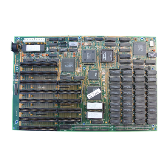
‘386 system, with multi-tasking and multi-user capabilities. This manual has been designed to be useful for two purposes. If your NEATsx is already set up in a functioning system you may want to review the manual to familiarize yourself with the features of the board and where things are. - Page 8 Introduction Board Layout The diagrams on the next two pages shows the layout of the NEATsx and the location of important components on the board. NEATsx Board Layout Key 1: Keyboard Connector 2: J3: Battery connector 3: JP 1: Video Mode selector...
-
Page 9: Board Layout
Introduction Neat SX Board Layout... - Page 10 Introduction Notes:...
-
Page 11: Hardware
AT to tower cases. It can use any version of MS- DOS above version 3.0, in addition to the OS/2 and Xenix/Unix oper ating systems. The NEATsx supports versions 3.2 and 4.0 of the Lo- tus-Intel-Microsoft (LIM) Expanded Memory Specification, more commonly called EMS. - Page 12 The NEATsx has a socket for an 80387SX math coprocessor. If an 80387SX chip is to be installed, make sure that it is clock speed compatible with the NEATsx. The 80387SX-16 is required if the sys tem is to operate at 16 Mhz.
- Page 13 Hardware Specifications The Expansion Bus The NEATsx uses a modified eight slot AT expansion bus. The bus is comprised of three 8-bit expansion slots and five 16-bit ex pansion slots. These will accept all the common expansion cards that conform to the standard slots. You should check to make sure that any cards added are speed compatible with the NEATsx.
- Page 14 Hardware Specifications 16-bit Slots The five sixteen-bit expansion slots provide a wider data trans mission pathway and will commonly be used by cards such as hard disk controllers, network cards and many I/O expansion cards. The slots are of two-piece construction with one long section and one short.
-
Page 15: Memory Subsystem
This section covers types of memory applicable to the NEATsx and the structure of the memory subsystem. The NEATsx can have up to eight megabytes of memory in stalled on the mainboard. A number of different kinds of memory chips or modules can be used. All of the memory on the mainboard uses a 16-bit data path to connect to the microprocessor. - Page 16 Hardware Specifications Types Of Memory The NEATsx accepts two different DRAM sizes. The memory subsystem accepts the following types of memory: • 256 Kbit DIP DRAM. 512KB per bank. Configured as two sets of two 44256 chips and one 41256 chip...
- Page 17 41256 chips. Nine 1 Mbit chips will equal one megabyte of memory. Each DIP RAM bank on the NEATsx has two sets of nine sockets. The figure on the next page shows the socket configuration of the DIP RAM banks.
- Page 18 Hardware Specifications ■ 44256/41000 sockets 41000 sockets 41256/41000 sockets NEATsx DIP RAM memory banks...
- Page 19 Hardware Specifications Physical Organization The NEATsx’s memory subsystem is divided into two parts which are in turn have two sections. The sections are called banks. There are four banks on the board, each with a capacity of two nine- chip sets. Two of the banks are for DIP DRAM chips, and two are for SIP modules.
- Page 20 44256/41256 configuration mentioned earlier. A bank must be completely full to function. Another nice feature of the NEATsx is that bank numbers can be reassigned so that SIP modules can be used first. Normally the DIP DRAM banks are assigned the zero and one positions.
- Page 21 In order for the system to perform interleaving, at least two banks must be filled. Therefore, a minimum of 1MB of RAM is neces sary for the NEATsx to utilize this feature. Memory interleaving is a special feature of the NEATsx that is setup before you receive the board.
- Page 22 Hardware Specifications Wait States One of the main things that distinguishes high-speed ‘286 and ‘386 system boards from earlier, slower designs is the way in which memory access is handled. At a slower clock speed, the common DRAM memory design had sufficient speed to provide memory ac cess for the microprocessor at zero wait states.
- Page 23 Shadow RAM If you have 1MB or more of memory installed, it is possible to use a feature of the NEATsx’s chip set called “Shadow RAM.” This allows the relocation of the contents of ROM BIOS to RAM above 640K. This feature increases overall system speed. Bear in mind that this can only be enabled if there is at least 1MB of memory present.
-
Page 24: Neatsx Chipset
Hardware Specifications Expanded Memory If at least 1MB of memory is installed on the NEATsx, the ex panded memory feature can be used. The NEAT ChipSet has a built-in memory controller for the LIM (Lotus-Intel-Microsoft) Expanded Memory Specification Version 3.2. When the driver EMM.SYS is loaded through the CONFIG.SYS file, the system supports EMS 4.0. - Page 25 QuickSet to setup the board. The 811 Chip The 82C811 is the bus controller for the CS8281 NEATsx CHIPSet. It provides synchronization and control signals for all buses. The 82C811 also provides an independent AT bus clock and allows for dynamic selection between the processor clock and a user-se...
- Page 26 The 812 Chip The 82C812 is the page/interleave and EMS memory control ler for the CS8281 NEATsx CHIPSet. It provides an interleaved mem ory subsystem design with page mode operation. It supports up to 8MB of DRAM with combinations of 256Kb and 1Mb DRAMS. The processor can operate at 16 Mhz with 0.5 to 0.7 wait state memory ac...
- Page 27 Hardware Specifications The programmable features are as follows: • Wait State selection • Selection of DRAM type (256K, or 1MB) • Interleave and Page Mode operation • Enäbling/disabling of Shadow RAM The 215 Chip The 82C215 Address/Data buffer provides the buffering and latching between the local CPU address bus and the Peripheral address bus.
-
Page 28: Rom Bios
Hardware Specifications The 206 Chip The 82C206 Integrated Peripherals controller contains the CMOS RAM that stores the configuration information created by the setup programs. It has the following features. The chip has the follow ing functions: • Programmable 8/10 Mhz DMA capability •... - Page 29 NEATsx disk replaces the AMI extended setup. Do not use the AMI Extended Setup program to setup your NEATsx unless you fully understand it. It is much more difficult to use correctly. You might lock yourself out of your system if the wrong configuration is entered.
-
Page 30: Peripheral Connections
If you wish to use a power supply that does not have a “power good” signal, you can do so by setting a jumper on the NEATsx board. Full details of this procedure are given in the Hardware Setup section. - Page 31 • A Keylock/Power-On LED indicator connector • A speed selection button connector • A Turbo speed LED indicator connector • A Speaker connector Information on how to connect these functions to the NEATsx can be found in the Hardware Setup section.
- Page 32 Hardware Specifications Real-Time Clock Battery The NEATsx has an onboard nickel cadmium battery (nicad) that maintains the system configuration information in the CMOS RAM. The battery automatically recharges while the power is on. It can be circumvented by using a battery pack of four “AA” batteries or a battery especially designed for this purpose, either of which are pur...
-
Page 33: Setup
Setup This section is for setting up the NEATsx before installing it in a system case. If your NEATsx is already installed in a system this section can be ignored unless a change in the system configuration needs to be made. - Page 34 Hardware Setup...
- Page 35 Video Mode Selection Jumper JP1 controls the video mode setting. The factory set ting is for monochrome mode. Alternatively, the NEATsx can be con figured for color mode. Short pins 1-2 for color; 2-3 (default) for monochrome. The figure below illustrates the settings.
- Page 36 Short pins 1-2 (default) for 32 Mhz, OSC1; pins 2-3 for option oscillator, OSC2. The factory setting (short 1-2) is shown in the figure below. Osc2 for 20 MHz O scl for 16M Hz operation operation (default) NEATsx CPU oscillator settings...
- Page 37 However, other power supplies may not and the alternative setting of JP4 allows for these types of power supplies to be used with the NEATsx. Short 1-2 for power good signal from the power supply; 2-3 (default) for on board power good signal. The fig...
- Page 38 Hardware Setup Battery Short pins 1-2 of jumper J2 to select the internal battery. Short 2-3 (default) for an external battery. External battery On board battery (default) NEATsx memory bank assignments...
- Page 39 If the SIP banks are assigned as Banks 0 and 1, the DIP socket banks cannot be used. Short 1-2: Bank 0, 1 DIP DRAM Socket; Bank 2, 3 SIP Socket. Short 2-3:SIP sockets are banks 0 and 1 NEATsx memory bank assignments...
-
Page 40: Before Installation Setup
It is important that memory banks be filled in pairs so that the page interleave function be enabled. The NEATsx can use up to four memory banks. The banks are numbered 0, 1, 2 and 3. There are a number of possible memory con... - Page 41 Hardware Setup DRAM TYPE TOTAL BANKO BANK1 BANK2 BANK3 MEMORY INTERLEAVE 256K 512KB 2. 1M 3. 256K 256K 4. 1M 5. 256K 256K 256K 1.5MB 6. 256K 256K 1M . 7. 1M 8. 256K 256K 256K 256K 9. 256K 256K 1 0 .1M NOTE: 1.
-
Page 42: After Installation Setup
Hardware Setup After Board Installation Setup After the NEATsx has been installed in a system case there are some additional connections that may be made to the board. The In stallation section contains a brief description of how to install the NEATsx system board in a case. - Page 43 Hardware Setup NEATsx case connectors...
- Page 44 Hardware Setup These connectors look similar to jumper switches and vary in number of pins. The indicators present on the case will have wire leads extending from them with plastic female connectors attached. The connectors should be plugged to the appropriate connecting pins on the board.
- Page 45 Hardware Setup PowerSippy The power supply connector on the NEATsx is made up of two six-pin male components in a line. Dual connectors from the power supply plug directly onto the connectors at the right rear of the board. The two female connectors from the power supply must be at...
- Page 46 Switching the Battery Source Jumper J2 controls the setting for either an internal or an exter nal battery. The NEATsx will normally be set to ran off its on-board battery if it is already installed in a system. Therefore, the factory set...
-
Page 47: Software
The hardware setup program records information about the structure of your system. It asks you to enter the time, date and infor mation about peripherals attached to the NEATsx. This includes dis play type and disk drive types. The program prompts for the informa... -
Page 48: The Neatsx Disk
The NEATsx Disk QuickSet The QuickSet setup utility is on the disk provided with the NEATsx. It is used to record information about the memory size, op erating speed, and overall configuration. QuickSet Documentation QuickSet comes with a document file on the disk that explains how to use the program and gives examples of possible memory con... - Page 49 Software Specifications EM S Driver File (EM M .SYS) In addition to the files mentioned above, the NEATsx disk has an EMS driver file that must be copied to the root directory of your operating system disk if EMS 4.0 is to be implemented.
- Page 50 Software Specifications...
-
Page 51: Setup
AMI BIOS The AMI BIOS setup program mentioned previously is used to establish the system hardware setup. If your NEATsx is already in stalled in a working system, you will not need to use this program un less you desire to modify the current configuration already in CMOS RAM. -
Page 52: Quiekset Setup Program
QuickSet is a copyrighted program supplied for use with the NEATsx system board. It is not public domain software and is not to be distributed or sold separately from the NEATsx board. The QuickSet setup program is designed to provide an easy way to record setup configuration for the NEAT ChipSet™... - Page 53 If EMS memory will be added, the appropriate information must be entered using section 3 (SET EMS MEMORY) of QuickSet. To use QuickSet the NEATsx board must be installed in a fully functioning system with a minimum of one floppy disk drive.
- Page 54 1. SET MEMORY TYPE AND SIZE Opening this section displays the memory selection chart. The chart contains more memory configurations than are possible for the NEATsx and identifies which ones can use the interleave feature.
- Page 55 Software Setup The similar chart in the Memory Subsystem portion of this manual lists only the allowable NEATsx configurations. Listed below for your reference is the memory selection chart from the Quickset program. DRAM TYPE TOTAL BANKO BANK1 BANK2 BANK3 MEMORY INTERLEAVE...
- Page 56 Software Setup 2. SET MEMORY WATT STATE Opening this section displays a list of available processor speeds as shown below. SYSTEM SPEED IS: 1 .12MHz 2 .16MHz 3. 20MHz Select the appropriate speed for your system (16 or 20 Mhz), then a wait-state selection list will appear.
- Page 57 Software Setup 20MHz NON-INTERLEAVE: 3 .0 WATT STATE, memory requirement is 60NS 4.1 WATT STATE, memory requirement is 80NS The wait-state is dependent on both the speed of RAM and the processor operating speed, determined by jumper JP2. The list notes the required RAM speed to use a particular wait-state setting.
- Page 58 Software Setup Disabling EMS returns you to the previous level. Enabling it will cause another menu to appear. The next and more detailed menu requests particular information required by the EMS setup. The next menu is as follows: 1. Select I/O port address for EMS use 2.
- Page 59 Software Setup 1. Select I/O port address for EMS use This item when selected will display the following list of port addresses. 1 .208H/209H 2 .218H/219H 3 .258H/259H 4. 268H/269H 5. 2A8H/2A9H 6. 2B8H/2B9H 7 .2E8H/2E9H Set I/O port Address, which is used for the EMS page register I/O base Address.
- Page 60 Software Setup_______________ 2. Set Starting Address for EMS Use This item when chosen will display the following list of base addresses. Set EMS base Address 1. C0000H - CFFFFH 2. C4000H - D3FFFH 3. C8000H - D7FFFH 4. CCOOOH - DBFFFH 5.
- Page 61 Software Setup 3. Set EMS Page 0 Address Extension 4. Set EMS Page 1 Address Extension 5. Set EMS Page 2 Address Extension 6. Set EMS Page 3 Address Extension Each of these four pages need to be set to one of four ranges. The choices will appear when an EMS Page Address Extension sec...
- Page 62 Software Setup 7. Select Total Memory Size for EMS Choosing this menu item displays the following list. Specify the Memory Size for EMS use 1.0.5 MB 2 . 1MB 3.2 MB 4.3 MB 5.4 MB 6.5 MB 7.6 MB 8.7 MB This section displays a list of the total memory available for EMS use.
- Page 63 Software Setup 4. SET SHADOW MEMORY Opening this section displays the following information. Set SHADOW memory SHADOW memory for ROM BIOS SHADOW memory for VIDEO BIOS Selecting one of the above causes another message to appear requesting whether or not to enable shadow RAM for ROM or VIDEO BIOS.
- Page 64 To make settings permanent, you must select #5 on the main menu, WRITE TO CMOS AND REBOOT. Other Configurations The QuickSet documentation file on the NEATsx disk goes through an example of one full configuration procedure using Quick- Set. This example and the instructions built into the program should provide adequate guidelines for establishing other configurations.
- Page 65 1) To copy the device driver to your system disk, do the fol lowing: If your system has two floppy disk drives and no hard disk drive, put the NEATsx disk in drive B, the system disk in drive A and type: COPY B-.EMM.SYS A:...
- Page 66 Software Setup If your system has a hard disk drive, put the NEATsx disk in drive A and type: COPY A:EMM.SYS C: You can also copy the document files in the same way by sub stituting their file names for EMM.SYS.
-
Page 67: Installation & Operation
If your NEATsx is not installed in a computer system, then the following basic information will be of use. Due to the wide variety of cases the NEATsx can be installed in, it is not possible to provide ex act instructions for every case. This section covers the factors common to installing the board in most situations. - Page 68 Installation & Operation Although areas with a humid climate are much less prone to static build-up, it is always best to safeguard against accidental dam age that may result in expensive repairs. The following measures should generally be sufficient to protect your equipment from static discharge: •...
- Page 69 Installation & Operation Mounting Holes The NEATsx has nine mounting holes drilled in the printed circuit board. These will line up with some or all of the mounting points on your case. Some form of mounting hardware is used to fas...
- Page 70 Installation & Operation Operation General When a NEATsx system first boots up several messages will appear on the screen. These messages come from BIOS and the NEATsx software. They include: • RAM test • BIOS Setup/Extended Setup program message • EMS status message if driver is installed on boot-up disk These messages include instructions on their use where appli...
- Page 71 Installation & Operation Reset Switch The NEATsx has a connector for a Reset button. If this has been connected to the front panel of your system case the button can be used to restart your system without turning the power off. Pushing the button will cause your system to restart from the memory test.
- Page 72 Installation & Operation Keyboard Switch The processing speed can also be changed using a keyboard command sequence. To use this feature do the following: • Hold down the <Ctrl> and <Alt> keys simultaneously and press: a + (plus) for the high speed, or a - (minus) for the low speed In practice you will probably always want to use the high speed mode unless you encounter software compatibility problems.
- Page 73 Clearing The CMOS RAM If incorrect setup values are recorded using the Quickset pro gram, it is possible the NEATsx will “hang”, i.e., the screen image will freeze and the system will not function even if you turn it off and on again.
- Page 74 Installation & Operation...
-
Page 75: Care & Maintenance
The master disk should be stored in a safe place. The NEATsx disk is not copy protected. If your system has a hard disk drive the contents of the NEATsx disk can be copied to it and run from there. - Page 76 Most computer users are familiar with the need to clean and maintain floppy disk drives. Your NEATsx is much less sensitive to contamination but it is nevertheless a good idea to examine the board and the devices con...
- Page 77 Care & Maintenance If you undertake the work yourself rather than taking the sys tem to a dealer or service center, do the following: • Turn off and disconnect all connections to the system. • Observe static precautions as covered in a previous section. •...
- Page 78 Care & Maintenance Extended Non-Use of the System If your system will be out of use for a number of weeks or more it is highly recommended that the back-up battery system de scribed earlier be used. This requires changing the jumper setting as described and connecting a battery pack or specially designed battery.
-
Page 79: Installing Upgrades
Memory Upgrades You may at some point want to change the original configura tion of your NEATsx by adding memory. There are a variety of ways to configure the NEATsx’s memory subsystem. As mentioned previ ously the NEATsx can use three different forms of DRAM. - Page 80 There are several points to remember when installing memory chips. As mentioned previously, do not attempt to modify the NEATsx if it is already installed in a system and doing the work your self will void your system warranty. These instructions assume a degree of technical knowledge and competence, and will not cover in detail anything other than the information related to chip installation.
- Page 81 Installing Upgrades...
- Page 82 The DRAM sockets on the board are standard notched sockets. To install chips, place the NEATsx board on a stable surface. Be very careful to safeguard against static electricity damage when installing chips. Install the chips individually as follows: •...
- Page 83 Make certain that you match the chip to a socket with the correct number of receptacles. If you use the wrong socket, the chip won’t work. 41000/44256 41000 1 Mbit sockets dual sockets 41256/41000 dual socket Both DIP RAM banks have the same socket arrangement NEATsx DIP RAM sockets...
- Page 84 Installing Upgrades ♦ Press chip into the socket Using either your fingers or a special chip inserting tool, press the chip into the socket. First gently press the chip in just a little; then check that all pins are going into the receptacles without bending. If the chip doesn’t go in smoothly, improve the alignment of the pins within the socket.
- Page 85 Installing Upgrades The SIP memory banks run vertically Bank 2 (0) Bank 3 ( 1 ) NEATsx SIP banks...
- Page 86 Installing Upgrades Math Coprocessor Installation A math coprocessor can be installed on the NEATsx to speed up calculation intensive operations. To do this, follow the standard chip installation procedures outlined earlier. The main difference lies in the means by which the correct orientation is determined.
- Page 87 80387sx socket 80387sx NEATsx 80387SX math chip installation The 80387sx chip has many pins which are all mounted on the sides of the chip. It is important to align the chip with the socket and care must be taken to avoid misalignment of the pins. For this reason you may wish to have the chip installed professionally.
- Page 88 Installing Upgrades...