Table of Contents
Advertisement
Copyright
This publication, including all photographs, illustrations and software, is protected
under international copyright laws, with all rights reserved. Neither this manual, nor
any of the material contained herein, may be reproduced without written consent of
the author.
Version 2.0
Disclaimer
The information in this document is subject to change without notice. The manufac-
turer makes no representations or warranties with respect to the contents hereof
and specifically disclaims any implied warranties of merchantability or fitness for
any particular purpose. The manufacturer reserves the right to revise this publica-
tion and to make changes from time to time in the content hereof without obligation
of the manufacturer to notify any person of such revision or changes.
Trademark Recognition
Microsoft, MS-DOS and Windows are registered trademarks of Microsoft Corp.
MMX, Pentium, Pentium-II, Pentium-III, Celeron are registered trademarks of Intel
Corporation.
Other product names used in this manual are the properties of their respective owners
and are acknowledged.
Federal Communications Commission (FCC)
This equipment has been tested and found to comply with the limits for a Class B
digital device, pursuant to Part 15 of the FCC Rules. These limits are designed to
provide reasonable protection against harmful interference in a residential instal-
lation. This equipment generates, uses, and can radiate radio frequency energy and,
if not installed and used in accordance with the instructions, may cause harmful
interference to radio communications. However, there is no guarantee that interfer-
ence will not occur in a particular installation. If this equipment does cause harmful
interference to radio or television reception, which can be determined by turning
the equipment off and on, the user is encouraged to try to correct the interference by
one or more of the following measures:
•
Reorient or relocate the receiving antenna
•
Increase the separation between the equipment and the receiver
•
Connect the equipment onto an outlet on a circuit different from that to
which the receiver is connected
•
Consult the dealer or an experienced radio/TV technician for help
Shielded interconnect cables and a shielded AC power cable must be employed with
this equipment to ensure compliance with the pertinent RF emission limits govern-
ing this device. Changes or modifications not expressly approved by the system's
manufacturer could void the user's authority to operate the equipment.
NM70-M USER MANUAL
Preface
Advertisement
Table of Contents

Related Manuals for ECS NM70-M


Summary of Contents for ECS NM70-M
- Page 1 Shielded interconnect cables and a shielded AC power cable must be employed with this equipment to ensure compliance with the pertinent RF emission limits govern- ing this device. Changes or modifications not expressly approved by the system’s manufacturer could void the user’s authority to operate the equipment. NM70-M USER MANUAL...
-
Page 2: Declaration Of Conformity
Provides information on us- page 25 ing the BIOS Setup Utility. Using BIOS Chapter 4 Describes the motherboard page 55 software. Using the Motherboard Software Chapter 5 page 59 Provides basic trouble shoot- Trouble Shooting ing tips. NM70-M USER MANUAL... -
Page 3: Table Of Contents
About the Setup Utility...............25 The Standard Configuration............25 Entering the Setup Utility............25 Resetting the Default CMOS Values........26 Using BIOS..................26 BIOS Navigation Keys..............27 Main Menu................28 Advanced Menu..............29 Chipset Menu................42 Tweak Menu................49 Boot Menu................51 Security Menu.................52 Exit Menu................53 Updating the BIOS..............54 NM70-M USER MANUAL... - Page 4 Using the Motherboard Software Auto-installing under Windows XP/7/8........55 ..Running Setup..............55 Manual Installation................57 ECS Utility Software (Intelligent EZ Utility) (Optional)....57 Chapter 5 Trouble Shooting Start up problems during assembly..........59 Start up problems after prolong use..........60 Maintenance and care tips..............60 Basic Troubleshooting Flowchart...........61...
-
Page 5: Introducing The Motherboard
Chapter 1 Introducing the Motherboard Introduction Thank you for choosing the NM70-M motherboard. This motherboard is a high ® performance, enhanced function. This motherboard has onboard Intel Celeron ICP1037U/847/807 or other Processors for high-end business or personal desktop markets. ®... -
Page 6: Specifications
Specifications ® • Onboard Intel Celeron ICP1037U/847/807 or other Processors Note: Please go to ECS website for the latest CPU support list. ® Chipset • Intel NM70 Chipset Memory • Dual-channel DDR3 memory architecture • 2 x 240-pin DDR3 DIMM socket supports up to 16 GB •... - Page 7 - Supports Dual/Triple Display (depends on display output) - Supports Multi-Language - Supports AC’97/HD Audio auto detect (default) AP Support • Supports eBLU*/eDLU/eSF* Note: *Microsoft .NET Framework 3.5 is required. Form Factor • Micro ATX Size, 210mm x 170mm NM70-M USER MANUAL...
-
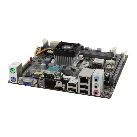
Page 8: Motherboard Components
Motherboard Components NM70-M USER MANUAL... - Page 9 15. PCIEX16 PCI Express slot for Graphics Interface 16. PCIE1~2 PCI Express X1 slots 17. F_AUDIO Front panel audio header 18. LDC Debug card header 19. COM2 Onboard serial port header 20. LPT Onboard parallel port header NM70-M USER MANUAL...
-
Page 10: I/O Ports
5. LAN Port Connect an RJ-45 jack to the LAN port to connect your computer to the Network. Link LED LAN LED Status Description No data Activity LED Orange blinking Active No link Link LED Green Link LAN Port NM70-M USER MANUAL... - Page 11 It is used to connect to a microphone. 9. HDMI Port (DVI port optional) You can connect the display device to the HDMI/DVI port. 10. PS/2 Keyboard (purple) Use the lower PS/2 port to connect a PS/2 keyboard. NM70-M USER MANUAL...
- Page 12 Memo NM70-M USER MANUAL...
-
Page 13: Installing The Motherboard
Place the motherboard over the mounting brackets and secure the motherboard onto the mounting brackets with screws. Do not over-tighten the screws as this can stress the motherboard. NM70-M USER MANUAL... -
Page 14: Checking Jumper Settings
The following illustration shows the location of the motherboard jumpers. Pin 1 is labeled. To avoid the system instability after clearing CMOS, we recommend users to enter the main BIOS setting page to “Load Default Settings” and then “Save and Exit Setup”. NM70-M USER MANUAL... -
Page 15: Installing Hardware
Install the DIMM module into the slot and press it firmly down until it seats correctly. Check that the cutouts on the DIMM module edge connector match the notches in the DIMM slot. The slot latches are levered upwards and latch on to the edges of the DIMM. NM70-M USER MANUAL... -
Page 16: Installing Add-On Cards
PCI Express Base Specification revision 2.0. Before installing an add-on card, check the documentation for the card carefully. If the card is not Plug and Play, you may have to manually configure the card before installation. NM70-M USER MANUAL... - Page 17 Please refer the following illustrations to install the add-on card: Install the LAN Card in the PCIE X1 slot Install the VGA Card in the PCIEX16 slot NM70-M USER MANUAL...
-
Page 18: Connecting Optional Devices
SATA 1 connector supports the Serial ATA 6Gb/s device, SATA2~4 connectors are used to support the Serial ATA 3Gb/s device, simpler disk drive cabling and easier PC assembly. It eliminates limitations of the current Parallel ATA interface. But maintains register compatibility and software compatibility with Parallel ATA. NM70-M USER MANUAL... - Page 19 2. SPDIFO: SPDIF Out Header This is an optional header that provides an SPDIFO (Sony/Philips Digital Interface) output to digital multimedia device through optical fiber or coaxial connector. 3. ME_UNLOCK: ME Unlock Header NM70-M USER MANUAL...
- Page 20 USB 2.0 connector to connect the front-mounted ports to the motherboard. Please make sure that the USB cable has the same pin assignment as indicated above. A different pin assignment may cause damage or system hang-up. NM70-M USER MANUAL...
- Page 21 97 Front Panel, please tick off the option of “ Disabled Front Panel Detect ”. If you use HD Audio Front Panel, please don’ t tick off “Disabled Front Panel Detect ” . * For reference only NM70-M USER MANUAL...
- Page 22 97 Front Panel, please don’ t tick off “Using Front Jack Detect ”. If you use HD Audio Front Panel, please tick off the option of “Using Front Jack Detect ”. * For reference only 7. LDC: Debug Card Header NM70-M USER MANUAL...
- Page 23 Connect a serial port extension bracket to this header to add a serial port to your system. 9. LPT: Onboard Parallel Port Header This header can be used to connect to the printer, scanner or other devices. NM70-M USER MANUAL...
-
Page 24: Installing A Sata Hard Drive
Attach either cable end to the connector on the motherboard. Attach the other cable end to the SATA hard drive. Attach the SATA power cable to the SATA hard drive and connect the other end to the power supply. * For reference only NM70-M USER MANUAL... -
Page 25: Connecting Case Components
Connector) Connect the CPU cooling fan cable to CPU_FAN. Connect the system cooling fan connector to SYS_FAN. Users please note that the fan connector supports the CPU cooling fan of 1.1A ~ 2.2A (26.4W max) at +12V. NM70-M USER MANUAL... - Page 26 3. ATX_POWER: ATX 24-pin Power Connector Connect the standard power supply connector to ATX_POWER. NM70-M USER MANUAL...
-
Page 27: Front Panel Header
50 ms to signal the power supply to switch on or off. The time requirement is due to internal de-bounce circuitry. After receiving a power on/off signal, at least two seconds elapses before the power supply recognizes another on/off signal. This concludes Chapter 2. The next chapter covers the BIOS. NM70-M USER MANUAL... - Page 28 Memo NM70-M USER MANUAL...
-
Page 29: Using Bios
When you power on the system, BIOS enters the Power-On Self Test (POST) routines. POST is a series of built-in diagnostics performed by the BIOS. After the POST routines are completed, the following message appears: Press DEL to enter SETUP NM70-M USER MANUAL... -
Page 30: Resetting The Default Cmos Values
Other options lead to dialog boxes that prompt you for informa- tion. Some options (marked with a triangle ) lead to submenus that enable you to change the values for the option. Use the cursor arrow keys to scroll through the items in the submenu. NM70-M USER MANUAL... -
Page 31: Bios Navigation Keys
BIOS items presented in this manual. The BIOS setup screens shown in this chapter are for reference only and may differ from the actual BIOS. Please visit the manufacture’s website for updated manual. NM70-M USER MANUAL... -
Page 32: Main Menu
The Date and Time items show the current date and time on the computer. If you are running a Windows OS, these items are automatically updated whenever you make changes to the Windows Date and Time Properties utility. NM70-M USER MANUAL... -
Page 33: Advanced Menu
CPU Configuration :Select Screen SATA Configuration USB Configuration :Select Item Super IO Configuration Enter : Select +/- : Change Opt. F1:General Help F2:Previous Values F3:Optimized Defaults F4:Save & Exit ESC:Exit Version 2.15.1229. Copyright (C) 2012 American Megatrends, Inc. NM70-M USER MANUAL... -
Page 34: Lan Configuration
F3:Optimized Defaults F4:Save & Exit ESC:Exit Version 2.15.1229. Copyright (C) 2012 American Megatrends, Inc. Onboard LAN Controller (Enabled) Use this item to enable or disable Onboard LAN 1 controller. Press <Esc> to return to the Advanced Menu page. NM70-M USER MANUAL... -
Page 35: Pc Health Status
If you choose Manual mode, the fan speed will be adjust depending on users’ parameters. Press <Esc> to return to the PC Health Status page. NM70-M USER MANUAL... - Page 36 System temperature, CPU & DIMM voltage, CPU & System fan speed... etc. • CPU Fan Speed • System Fan Speed • CPU Voltage • DIMM Voltage Press <Esc> to return to the Advanced Menu page. NM70-M USER MANUAL...
-
Page 37: Power Management Setup
EUP Function (Enabled) This item allows user to enable or disable EUP support. Power LED Type (Dual Color LED) This item shows the type of the power LED. Press <Esc> to return to the Advanced Menu page. NM70-M USER MANUAL... -
Page 38: Acpi Configuration
Version 2.15.1229. Copyright (C) 2012 American Megatrends, Inc. ACPI Sleep State [S3(Suspend to RAM)] This item allows user to enter the ACPI S3 (Suspend to RAM) Sleep State (default). Press <Esc> to return to the Advanced Menu page. NM70-M USER MANUAL... -
Page 39: Cpu Configuration
This item shows that the computer supports Intel HT Technology or not. Intel VT-x Technology (Supported) This item shows that the computer supports Intel VT-x Technology or not. This picture takes CPU 847 for reference only, please refer to the actual motherboard as standard. NM70-M USER MANUAL... - Page 40 Use this item to control the time window over PL1 value should be maintained. Short duration power limit (0) CPU will use this power limit for a very short duration. After that, the long duration power limit will be honored. Press <Esc> to return to the Advanced Menu page. NM70-M USER MANUAL...
-
Page 41: Sata Configuration
SATA Port1~4 (Empty) This motherboard supports four SATA channels, each channel allows one SATA device to be installed. Use these items to configure each device on the SATA channel. Press <Esc> to return to the Advanced Menu page. NM70-M USER MANUAL... -
Page 42: Usb Configuration
All USB Devices (Enabled) Use this item to enable or disable all USB devices. Legacy USB Support (Enabled) Use this item to enable or disable support for legacy USB devices. Press <Esc> to return to the Advanced Menu page. NM70-M USER MANUAL... -
Page 43: Super Io Configuration
This item allows you to enable or disable serial port. Device Settings (IO=3F8h; IRQ=4) This item shows the information of the device settings. Change Settings (Auto) Use this item to change device settings. Press <Esc> to return to the Super IO Configuration page. NM70-M USER MANUAL... - Page 44 This item allows you to enable or disable serial port. Device Settings (IO=2F8h; IRQ=3) This item shows the information of the device settings. Change Settings (Auto) Use this item to change device settings. Press <Esc> to return to the Super IO Configuration page. NM70-M USER MANUAL...
- Page 45 Use this item to change device settings. Device Mode (Standard Parallel P...) This item shows the information of the device mode. Press <Esc> to return to the Super IO Configuration page. Press <Esc> to return to the Advanced Menu page. NM70-M USER MANUAL...
-
Page 46: Chipset Menu
When set to Fixed Mode, the graphics driver will reserve a fixed position of the system memory as graphics memory, according to system and graphics requirements. IGD Multi-Monitor (Disabled) This item enables or disables IGD (Internal Graphics devices) multi-monitor. Press <Esc> to return to the Chipset Menu page. NM70-M USER MANUAL... - Page 47 Intel integrated Graphics and one or two PCI-Express graphics devices under Windows 7/8. Step 1. Insert ECS drives DVD to run Auto setup or browse the DVD to install Intel chipset drivers, VGA and sound drivers.(If you want know the detail information, please refer to chapter 4.)
- Page 48 IGD Memory [64M] DVMT/FIXED Memory [256M] IGD Multi-Monitor [Disabled] :Select Screen :Select Item Enter : Select +/- : Change Opt. F1:General Help F2:Previous Values F3:Optimized Defaults F4:Save & Exit ESC:Exit Version 2.15.1229. Copyright (C) 2012 American Megatrends, Inc. NM70-M USER MANUAL...
-
Page 49: Display Devices
Extend desktop to this display You must select Apply before making additional changes. Disconnect this display Make this my main display Advance settings Make text and other items larger or smaller What display settings should I choose? Cancel Apply NM70-M USER MANUAL... - Page 50 Multiple displays: Extend desktop to this display You must select Apply before making additional changes. Make this my main display Advance settings Make text and other items larger or smaller What display settings should I choose? Cancel Apply NM70-M USER MANUAL...
-
Page 51: Pch Configuration
This item enables or disables the warning if the case is opened up, and the item below indicates the current status of the case. Chassis Opened (No) This item indicates whether the case has been opened. Press <Esc> to return to the Chipset Menu page. NM70-M USER MANUAL... - Page 52 F1:General Help F2:Previous Values F3:Optimized Defaults F4:Save & Exit ESC:Exit Version 2.15.1229. Copyright (C) 2012 American Megatrends, Inc. ME FW Version (8.1.30.1350) This item shows the ME FW version. Press <Esc> to return to the Chipset Menu page. NM70-M USER MANUAL...
-
Page 53: Tweak Menu
Memory Frequency (1333 MHz) This item shows the memory frequency. Total Memory (2048 MB (DDR3)) This item shows the total memory. This picture takes CPU 847 for reference only, please refer to the actual motherboard as standard. NM70-M USER MANUAL... - Page 54 2. Press and hold the “Page Up Key (PgUp)” of the keyboard, and then boot the PC 3. Two seconds after the PC boots up, release the “Page Up Key (PgUp)”. 4. The BIOS returns to the default setting by itself. NM70-M USER MANUAL...
-
Page 55: Boot Menu
Use this item to select boot mode. Set Boot Priority This item enables you to set boot priority for all boot devices. Boot Option #1 /2 /3 /4 /5 /6 /7 These items show the boot priorities. NM70-M USER MANUAL... -
Page 56: Security Menu
Secure Boot state (Disabled) This item allows you to enable or disable the secure boot state. Secure Boot (Disabled) This item is used to control the secure boot flow, it is possible only if system runs in User Mode. NM70-M USER MANUAL... -
Page 57: Exit Menu
This item enables you to save the changes that you have made as user defaults. Restore User Defaults This item enables you to restore the user defaults. Boot Override Use this item to select the boot device. NM70-M USER MANUAL... -
Page 58: Updating The Bios
BIOS jumper, reset the jumper to protect the newly installed BIOS from being overwritten. The computer will restart automatically. This concludes Chapter 3. Refer to the next chapter for information on the software supplied with the motherboard. NM70-M USER MANUAL... -
Page 59: Using The Motherboard Software
Click Setup. The installation program begins: The following screens are examples only. The screens and driver lists will be different according to the motherboard you are installing. The motherboard identification is located in the upper left-hand corner. NM70-M USER MANUAL... - Page 60 Windows 8 will show the following screen after system restart, you must select “Desktop” in the bottom left to install the next driver. NM70-M USER MANUAL...
-
Page 61: Manual Installation
ECS Utility Software (Intelligent EZ Utility) (Optional) ECS Intelligent EZ Utility provides friendly interfaces under Windows O.S, which makes your computing more easily and conveniently. These software(s) are subject to change at anytime without prior notice. Please refer to the support disk for available software. - Page 62 Just select the one you prefer and start to download and install the drivers. eBLU ECS eBLU utility makes BIOS update faster and easier. eBLU will list the latest BIOS with a default check-mark. Click”install” button to install. Microsoft .NET Framework 3.5 is required.
-
Page 63: Trouble Shooting
Before calling for technical support or returning for warranty, this chapter may help to address some of the common questions using some basic troubleshooting tips. You may also log onto our ECS website for more information: http:// www.ecs.com.tw/ECSWebSite/Support/Support_FAQ.aspx?MenulD=49& childid=M 49&LanlD=0 a) System does not power up and the fans are not running. -
Page 64: Start Up Problems After Prolong Use
4. Check whether there is any bulked up electrolytic capacitor or abnormal component. Please logo onto our ECS website: http://www.ecs.com.tw/ECSWebSite/Support/ Technical_Support_List.aspx?MenuID=50&LanID=0 for more information. Maintenance and care tips Your computer, like any electrical appliance, requires proper care and maintenance. - Page 66 Memo NM70-M USER MANUAL...