Table of Contents
Advertisement
Copyright
This publication, including all photographs, illustrations and software, is protected un-
der international copyright laws, with all rights reserved. Neither this manual, nor any
of the material contained herein, may be reproduced without written consent of the au-
thor.
Version 1.0d
Disclaimer
The information in this document is subject to change without notice. The manufac-
turer makes no representations or warranties with respect to the contents hereof and
specifically disclaims any implied warranties of merchantability or fitness for any par-
ticular purpose. The manufacturer reserves the right to revise this publication and to
make changes from time to time in the content hereof without obligation of the manu-
facturer to notify any person of such revision or changes.
Trademark Recognition
Microsoft, MS-DOS and Windows are registered trademarks of Microsoft Corp.
nVIDIA is a registered trademark of nVIDIA Corporation.
AMD, Athlon, and Duron are registered trademarks of AMD Corporation.
Other product names used in this manual are the properties of their respective owners
and are acknowledged.
Federal Communications Commission (FCC)
This equipment has been tested and found to comply with the limits for a Class B digi-
tal device, pursuant to Part 15 of the FCC Rules. These limits are designed to provide
reasonable protection against harmful interference in a residential installation. This
equipment generates, uses, and can radiate radio frequency energy and, if not in-
stalled and used in accordance with the instructions, may cause harmful interference
to radio communications. However, there is no guarantee that interference will not oc-
cur in a particular installation. If this equipment does cause harmful interference to
radio or television reception, which can be determined by turning the equipment off
and on, the user is encouraged to try to correct the interference by one or more of the
following measures:
−
Reorient or relocate the receiving antenna.
−
Increase the separation between the equipment and the receiver.
−
Connect the equipment onto an outlet on a circuit different from that to which
the receiver is connected.
−
Consult the dealer or an experienced radio/TV technician for help.
Shielded interconnect cables and a shielded AC power cable must be employed with
this equipment to ensure compliance with the pertinent RF emission limits governing
this device. Changes or modifications not expressly approved by the system's manu-
facturer could void the user's authority to operate the equipment.
Preface
Advertisement
Table of Contents

Related Manuals for ECS N2U400-A


Summary of Contents for ECS N2U400-A
- Page 1 Preface Copyright This publication, including all photographs, illustrations and software, is protected un- der international copyright laws, with all rights reserved. Neither this manual, nor any of the material contained herein, may be reproduced without written consent of the au- thor.
- Page 2 Declaration of Conformity This device complies with part 15 of the FCC rules. Operation is subject to the follow- ing conditions: − This device may not cause harmful interference, and − This device must accept any interference received, including interference that may cause undesired operation.
- Page 3 Features Translations Caractéristiques Processeur La carte mère utilise un Socket A AMD 462 broches présen- tant les caractéristiques suivantes: • Supporte un bus frontal (FSB) de 400/333/266/200MHz • Peut recevoir les CPU AMD Athlon XP/Sempron/Athlon/Duron • Transfert DDR (Double Data Rate) 200/166/133 MHz sur adresse CPU AMD Athlon XP/Sempron/Athlon/Duron et bus de données ®...
- Page 4 ment) • Deux connecteurs IDE supportant quatre canaux IDE et une interface de lecteur de disquette La carte mère supporte la maîtrise de bus Ultra DMA avec des vitesses de transfert de 33/66/100/133 Mo/sec. LAN Interne Le VT6103 est un périphérique à Couche Physique pour (optionnel) Ethernet 10BASE-T et 100BASE-TX utilisant des câbles Non blindés de catégorie 5, Blindés de Type 1, et à...
- Page 5 Features Prozessor Das Motherboard verwendet einen AMD 462-Pin Sockel A mit den folgenden Eigenschaften: • Unterstützung für 400/333/266/200 MHz FrontSideBus (FSB) • Nimmt AMD Athlon XP/Sempron/Athlon/Duron -CPU auf. • 200/166/133MHz DDR (Double Data Rate) Transfer auf AMD Athlon XP/Sempron/Athlon/Duron CPU-Adressen- und Datenbussen ®...
- Page 6 Schnittstelle für ein Floppydiskettenlaufwerk unterstützen Das Motherboard unterstützt Ultra DMA Bus-Mastering mit Übertragungsraten von 33/66/100/133 MB/Sek. Onboard-LAN Das VT6103 ist ein Physical-Layer-Gerät für Ethernet (optional) 10BASE-T und 100BASE-TX bei Benutzung von nicht abgeschirmten Kategorie 5-Kabeln, abgeschirmten Typ 1- Kabeln und Glasfaserkabeln. •...
- Page 7 Caratteristiche Processore La scheda madre è dotata di un socket A AMD a 462 pin che presenta le seguenti caratteristiche: • Supporta il bus di sistema 400/333/266/200 MHz frontside (FSB) • Possibilità di alloggiare le CPU AMD Athlon XP/Sempron/ Athlon/Duron •...
- Page 8 LAN integrata La scheda VT6103 è un dispositivo Physical Layer per (opzionale) Ethernet 10BASE-T e 100BASE-TX che usa cavi della categoria 5 non schermati, Tipo 1 schermati e ottici. • Dual Speed – 100/10 Mbps • Half e Full Duplex •...
- Page 9 Características Procesador El panel principal usa un AMD 462-pines Enchufe A que tiene las siguientes características: • Permite 400/333/266/200 MHz bus de lado frontal (FSB) • Acomoda una CPU AMD Athlon XP/Sempron/Athlon/Duron • Transferencia de 200/166/133 MHz DDR (Double Data Rate/Índice de Datos Doble) en dirección AMD Athlon XP/Sempron/Athlon/Duron CPU y buses de datos ®...
- Page 10 La VT6103 es un componente Estrato Físico para Ethernet Incorporada 10BASE-T y 100BASE-TX usando categoría 5 no blindado, (opcional) Tipo 1 Blindado, y cables de Fibra óptica. • Velocidad Doble – 100/10 Mbps • Bidireccional Total y Medio • Reúne Todo la Apropiado IEEE 802.3, 10Base-T y 100Base-Tx Convencionales •...
- Page 11 製品特徴 プロセッサ 当メインボードはAMD 462ピンソケットを搭載し、次の特長が あります: • 400/333/266/200 MHzフロントサイドバス(FSB)をサ ポート • AMD Athlon XP/Sempron/Athlon/Duron CPUに対応 • AMD Athlon XP/Sempron/Athlon/Duron CPUのアドレスバスとデータバスを200/166/133 MHz DDR (Double Data Rate) の転送率でサポート ® チップセット このメインボードには、 NVIDIA nForce 2 Ultra-400 Northbridge と NVIDIA ® nForce MCP Southbridgeとのチッ プセットが搭載されています。これらチップセットの一部の 特徴は次の通りです:...
- Page 12 拡張オプション このメインボードには次の拡張オプションがあります: • 5つの32ビットPCIスロット • 1つのAGPスロット (1.5V AGPインターフェースのみ対応) • 2つのIDEコネクタ(4つのIDEチャンネルとフロッピーデ ィスクドライブインターフェースをサポート可能) メインボードはUltra DMA バスマスタ機能、33/66/100/133 MB/秒の転送レートをサポートします。 オンボードLAN VT6103はカテゴリ5案シールド、Type 1 シールド、光ファイ (オプション) バーケーブルを使ったEthernet 10BASE-Tと100BASE- TXのための物理レイヤーです。 • デュアルスピード – 100/10 Mbps • 半/全二重 • IEEE 802.3、10Base-T、100Base-Tx標準にすべて対応 • 適応エコライザ 統合入出力ポート このメインボードにはフルセットのI/Oポートおよびコネクタ が搭載しています。 • 2つのマウスおよびキーボード向けPS/2ポート •...
- Page 13 기능 프로세서 이 메인보드는 AMD 462 핀 소켓 A 를 사용하며 다음과 같은 특징을 지닌다: • 400/333/266/200 MHz frontside bus (FSB) 지원 • AMD Athlon XP/Sempron/Athlon/Duron CPU를 사용한다. • AMD Athlon XP/Sempron/Athlon/Duron CPU 어드레스 및 데이터 버스에서의200/166/133 MHz DDR (Double Data Rate) 전송...
- Page 14 Onboard LAN VT6103 는 카테고리 5 언실드, 타입 1 실드, 유리 섬유 (선택 사항) 케이블을 사용한 Ethernet 10BASE-T와 100BASE-TX 를 위한 물리적 레이어 장치이다. • 듀얼 스피드 – 100/10 Mbps • Half 및 Full Duplex • IEEE 802.3, 10Base-T 및 100Base-Tx 표준 부합 •...
- Page 15 性能 處理器 本主機板採用了具有下列功能之AMD 462針Socket A: • 支援高達400/333/266/200 MHz之系統匯流排 (FSB) • 支援AMD Athlon XP/Sempron/Athlon/Duron 處理器 • 支援高達200/166/133MHz DDR (Double Data Rate, 雙倍速資料傳輸) 之AMD Athlon XP/Sempron/Athlon/Duron CPU 位址和數據匯流排傳輸 ® ® 本主機板整合有 NVIDIA nForce 2 Ultra-400 北橋及 NVIDIA 晶片組 nForce MCP 南橋晶片組。以下為此晶片組的部份功能: • 對MCP南橋晶片組提供傳輸速率高達...
- Page 16 內建網路功能 VT6103係為乙太10BASE-T 和 100BASE-TX之實體層元件, 使用 Category 5(速率100 Mbps) 無遮蔽式雙絞線, Type 1屏蔽電纜以及 (選購) 光纖電纜。 • 雙倍速 – 100/10 Mbps 傳輸速率 • 支援半或全雙工運作模式 • 適用於所有可用之IEEE 802.3, 10BaseT和100Base-Tx雙絞線, 等之標準 • 自適均衡器 已整合的I/O 本主機板完整地支援各種 I輸出入及連接器: • 2個 PS/2 埠,分供滑鼠及鍵盤連接 • 1個串列埠 • 1個平行埠 • 4個USB埠...
- Page 17 特性 处理器 主板使用一个 AMD 462-pin Socket A 插座,此插座具有以下 特点: • 支持400/333/266/200 MHz 前端总线 (FSB) • 支持 AMD Athlon XP/Sempron/Athlon/Duron CPU • AMD Athlon XP/Sempron/Athlon/Duron CPU 地址和数据总线上200/166/133 MHz DDR(双数据传输率)传输 ® ® 芯片组 此主板集成了 NVIDIA nForce 2 Ultra-400 北桥和 NVIDIA nForce MCP 南桥芯片组。此芯片组具有以下一些高级功能: •...
- Page 18 • 2 个用于连接鼠标和键盘的 PS/2 端口 • 1 个串口 • 1 个并口 • 4 个 USB 端口 • 1 个 LAN 端口 • 麦克风、线入和线出声音插孔 BIOS 此主板使用 Award BIOS,可以让用户自己配置以下系统功能: • 电源管理 • 唤醒报警 • CPU 参数 • CPU 和记忆定时 还可用于设置不同处理器时钟速度的参数。 部分硬件规格和软件项目若有更改恕不另行通知。 xviii...
-
Page 19: Table Of Contents
Preface Features Translations CHAPTER 1 Introducing the Motherboard Introduction ....................1 Features .....................2 Motherboard Components ................4 CHAPTER 2 Installing the Motherboard Safety Precautions..................6 Choosing a Computer Case ...............6 Quick Guide ....................6 Installing the Motherboard in a Case ............7 Checking Jumper Settings ................7 Setting Jumpers .................... - Page 20 Power Management Setup ................35 PNP/PCI Configurations................36 PC Health Status.................... 37 Load Fail-Safe Defaults................. 38 Load Optimized Defaults................38 Set Supervisor/User Password ............... 38 Save & Exit Setup ..................39 Exit Without Saving ..................39 CHAPTER 4 Using the Motherboard Software About the Software CD-ROM ..............40 Auto-installing under Windows 98/ME/2000/XP ........40 Running Setup ....................
-
Page 21: Introducing The Motherboard
AC 97 interface. It also features AGP3.0 8X host interface, HyperTransport interface and support Front Side Bus (FSB) up to 400/333/266 MHz. The N2U400-A motherboard provides an advanced set of I/O ports, such as dual channel IDE interfaces, a floppy controller, one high-speed serial port, an... -
Page 22: Features
Processor The motherboard uses a 462-pin Socket that has the following features: • Supports 400/333/266/200 MHz Front Side Bus (FSB) • Accommodates AMD Athlon XP/Sempron/Athlon/Duron • 200/166/133 MHz DDR (Double Data Rate) transfer on Athlon XP/Sempron/Athlon/Duron CPU address and data buses ®... - Page 23 Onboard LAN The VT6103L is a Physical Layer device for Ethernet 10BASE- (optional) T and 100BASE-TX using category 5 Unshielded, Type 1 Shielded, and Fiber Optic cables. • Dual Speed – 100/10 Mbps • Half And Full Duplex • Meet All Applicable IEEE 802.3, 10Base-T and 100Base- Tx Standards •...
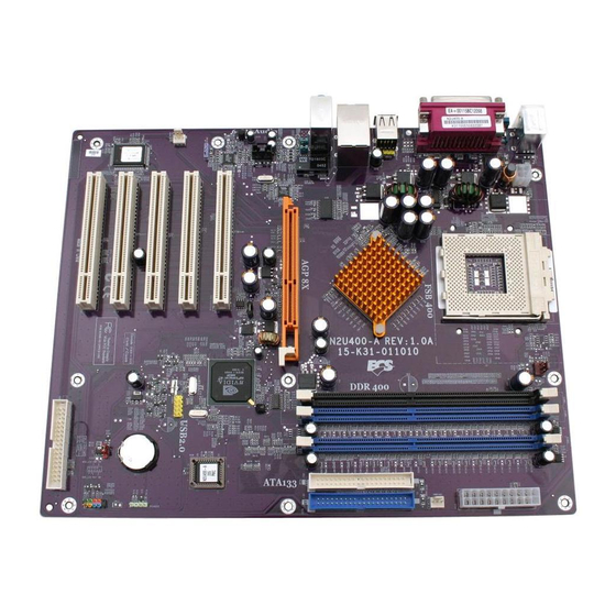
- Page 25 Table of Motherboard Components Label Component Accelerated Graphics Port (supports 1.5V AGP card only) ATX1 Standard 20-pin ATX power connector ATX2 ATX 12V Power Connector AUDIO1 Front audio connector CASFAN1 Case fan connector CDIN1 Primary CD-in connector CPU SOCKET Socket A for AMD CPU CPUFAN1 Cooling fan for CPU DIMM1~ DIMM3...
-
Page 26: Installing The Motherboard
Installing the Motherboard Follow these safety precautions when installing the motherboard: • Wear a grounding strap attached to a grounded device to avoid damage from static electricity. • Discharge static electricity by touching the metal case of a safely grounded object before working on the motherboard. •... -
Page 27: Installing The Motherboard In A Case
Refer to the following illustration and instructions for installing the mother- board in a case: This illustration shows an ex- 2. Secure the mainboard with ample of a motherboard being screws where appropriate. installed in a tower-type case: Note: Do not overtighten the screws as this can stress the moth- erboard. -
Page 28: Checking Jumper Settings
Checking Jumper Settings The following illustration shows the location of the motherboard jumpers. Pin 1 is labeled. Jumper Settings Jumper Type Description Setting (default) 1-2: Normal 3-pin Clear CMOS 2-3: Clear CMOS Before clearing CMOS, make sure to turn off the system. -
Page 29: Connecting Case Components
After you have installed the motherboard into a case, you can begin connect- ing the motherboard components. Refer to the following: Connect the Pentium 4 auxiliary power supply connector to ATX2. Connect the standard power supply connec- tor to ATX1. Connect the CPU cooling fan cable to CPUFAN1. - Page 30 CPUFAN1/CASFAN1/PWRFAN1: FAN Power Connectors Signal Name Function System Ground +12V Power +12V Sense Sensor SPEAKER1: Internal speaker Signal Name Signal Ground...
-
Page 31: Front Panel Connector
Front Panel Connector The front panel connector (PANEL1) provides a standard set of switch and LED connectors commonly found on ATX or micro-ATX cases. Refer to the table below for information: Signal Function Signal Function Hard disk LED MSG LED [dual color HD_LED_P FP PWR/SLP (positive) -
Page 32: Installing Hardware
Installing the Processor Caution: When installing a CPU heatsink and cooling fan make sure that you DO NOT scratch the motherboard or any of the surface-mount resis- tors with the clip of the cooling fan. If the clip of the cooling fan scrapes across the motherboard, you may cause serious damage to the mother- board or its components. - Page 33 CPU Installation Procedure This motherboard is built with Socket 462 processor socket. When choosing a processor, consider the performance requirements of the system. The follow- ing illustration shows CPU installation components: Step 1 Step 2 Step 3 Step 4 Orient the CPU so the odd corner matches the odd corner of the socket. With the lever in an upright position, gently place the CPU on the socket;...
- Page 34 Installing CPU Fan and Fan Connector CPU fan and heatsink installation procedures may vary with the type of CPU fan/heatsink supplied. The form and size of fan/heatsink may also vary. With- out an effective cooling fan, the CPU can overheat and cause damage to both CPU and the motherboard.
-
Page 35: Installing Memory Modules
Installing Memory Modules This motherboard accommodates three 184-pin 2.5V unbuffered non-ECC Double Data Rate (DDR) SDRAM memory modules. This motherboard can support DDR266/DDR333/DDR400 memory modules and allow up to 6.4 GB/s data transfer rate. Utilizing the dual-channel DDR memory architecture, this motherboard provides a solution which doubles the system memory bandwidth of your system memory and boost the system per- formance. - Page 36 Install any remaining DIMM modules. Table A: Recommended dual-channel DDR configurations DIMM1 DIMM2 DIMM3 Dual Channel √ √ √ √ √ √ √ √ √ √ Note: When using dual channel mode, install only similar (same density, DRAM technology and DRAM bus width) module for each channel. Table B: CPU FSB and Memory Frequency CPU FSB DDR Module support...
-
Page 37: Installing A Hard Disk Drive/Cd-Rom
Installing a Hard Disk Drive/CD-ROM This section describes how to install IDE devices such as a hard disk drive and a CD-ROM drive. Your motherboard has a primary and secondary IDE channel interface (IDE1 and IDE2). An IDE ribbon cable supporting two IDE devices is bundled with the moth- erboard. -
Page 38: Installing A Floppy Diskette Drive
IDE devices have jumpers or switches that are used to set the IDE device as MASTER or SLAVE. Refer to the IDE device user’s manual. When installing two IDE devices on one cable, ensure that one device is set to MASTER and the other device is set to SLAVE. -
Page 39: Installing Add-On Cards
Installing Add-on Cards The slots in this motherboard are designed to hold expansion cards and con- nect them to the system bus. Expansion slots are a means of adding or enhancing the motherboard’s features and capabilities. With these efficient facilities, you can increase the motherboard’s capabilities by adding hardware which performs tasks that are not part of the basic system. -
Page 40: Connecting Optional Devices
Connecting Optional Devices Refer to the following for information on connecting the motherboard’s op- tional devices: AUDIO1: Front Panel Audio header This header allows the user to install auxiliary front-oriented microphone and line-out ports for easier access. Signal Name Function AUD_MIC Front Panel Microphone input signal AUD_GND... - Page 41 USB3: Front panel USB connectors The motherboard has four USB ports installed on the rear edge I/O port array. Additionally, some computer cases have USB ports at the front of the case. If you have this kind of case, use auxiliary USB connector USB3 to connect the front-mounted ports to the motherboard.
- Page 42 SPDIFO1: SPDIF out header (optional) This is an optional header that provides an S/PDIF (Sony/Philips Digital Inter- face) output to digital multimedia device through optical fiber or coaxial connector. Signal Name Function SPDIF SPDIF digital output +5VA 5V analog power Not connected Ground...
-
Page 43: Connecting I/O Devices
The backplane of the motherboard has the following I/O ports: PS/2 Mouse Use the upper PS/2 port to connect a PS/2 pointing device. PS/2 Keyboard Use the lower PS/2 port to connect a PS/2 keyboard. LPT1 Use LPT1 to connect printers or other parallel communica- tions devices. -
Page 44: Using Bios
Using BIOS The computer uses the latest Award BIOS with support for Windows Plug and Play. The CMOS chip on the motherboard contains the ROM setup instruc- tions for configuring the motherboard BIOS. The BIOS (Basic Input and Output System) Setup Utility displays the system's configuration status and provides you with options to set system parameters. -
Page 45: Entering The Setup Utility
Entering the Setup Utility When you power on the system, BIOS enters the Power-On Self Test (POST) routines. POST is a series of built-in diagnostics performed by the BIOS. After the POST routines are completed, the following message appears: Press DEL to enter SETUP Pressing the delete key accesses the BIOS Setup Utility: BIOS Navigation Keys... -
Page 46: Using Bios
If your motherboard has a BIOS protection jumper, change the setting to allow BIOS flashing. If your motherboard has an item called Firmware Write Protect in Advanced BIOS features, disable it. (Firmware Write Protect prevents BIOS from being overwritten.) Create a bootable system disk. (Refer to Windows online help for infor- mation on creating a bootable system disk.) Download the Flash Utility and new BIOS file from the manufacturer's Web site. -
Page 47: Standard Cmos Features
Standard CMOS Features In the Standard CMOS menu you can set the system clock and calendar, re- cord disk drive parameters and the video subsystem type, and select the type of errors that stop the BIOS POST. Date and Time The Date and Time items show the current date and time on the computer. - Page 48 IDE HDD Auto-Detection Press <Enter> while this item is highlighted to prompt the Setup Utility to automatically detect and configure an IDE device on the IDE channel. Note: If you are setting up a new hard disk drive that supports LBA mode, more than one line will appear in the parameter box.
-
Page 49: Advanced Bios Features
Advanced BIOS Features This option defines advanced information about your system. Virus Warning (Disabled) When enabled, this item provides protection against viruses that try to write to the boot sector and partition table of your hard disk drive. You need to disable this item when installing an operating system. - Page 50 Second, and Third boot devices. Swap Floppy Drive (Disabled) If you have two floppy diskette drives in your system, this item allows you to swap the assigned drive letters so that drive A becomes drive B, and drive B becomes drive A. Boot Up Floppy Seek (Disabled) If this item is enabled, it checks the size of the floppy disk drives at start-up time.
-
Page 51: Advanced Chipset Features
Small Logo (EPA) Show (Disabled) Determines whether or not the EPA logo appears during boot up. ATA 66/100 Cable MSG (Enabled) This item enables or disables the display of the ATA 66/100 Cable MSG. Advanced Chipset Features The Advanced Chipset Features option is used to change the values of the chipset registers. - Page 52 Memory Timings (Optimal) This item allows you to set the Memory Timings. The following four items be- come available when this item is set to Expert. T(RAS) (7) This item defines the timing delay for DRAM precharge. T(RCD) (1) This item defines the timing of the transition from RAS (row address strobe) to CAS (column address strobe) as both rows and columns are separately ad- dressed shortly after DRAM is refreshed.
-
Page 53: Integrated Peripherals
Integrated Peripherals These options display items that define the operation of peripheral compo- nents on the system's input/output ports. OnChip IDE Channel 0/Channel 1 (Enabled) The chipset contains a PCI IDE interface with support to two IDE channels. Select Enabled to activate the primary/secondary IDE interface. Select Dis- abled to deactivate the primary/secondary interface. - Page 54 USB Keyboard Support (Disabled) Select Enabled if your system contains a Universal Serial Bus (USB) control- ler and you have a USB keyboard. AC97 Audio (Auto) This item allows you to control the onboard AC97 Audio. MAC Lan (nVIDIA) (Auto) This option allows you to enable/disable the Onboard LAN Controller.
-
Page 55: Power Management Setup
Power Management Setup The Power Management Setup Menu option is used to change the values of the chipset registers for system power management. Power Management This category allows you to select the type (or degree) of power saving mode settings. Min Saving Minimum power management. -
Page 56: Pnp/Pci Configurations
PWRON After PWR-Fail (Off) This item allows you to select power on function when power fail. PNP/PCI Configurations This option configures how PnP (Plug and Play) and PCI expansion cards operate in your system. Both the ISA and PCI buses on the Motherboard use system IRQs (Interrupt ReQuests) and DMAs (Direct Memory Access). -
Page 57: Pc Health Status
IRQ Resources (Press Enter) When the previous item is set to manual, this item allows you respectively assign an interruptive type for IRQ-3, 4, 5, 7, 9, 10, 11, 12, 14, and 15. PCI/VGA Palette Snoop (Disabled) This item is designed to overcome problems that can be caused by some non- standard VGA cards. -
Page 58: Load Fail-Safe Defaults
Load Fail-Safe Defaults This option opens a dialog box that lets you install fail-safe defaults for all ap- propriate items in the Setup Utility: Press <Y> and then <Enter> to install the defaults. Press <N> and then <En- ter> to not install the defaults. The fail-safe defaults place no great demands on the system and are generally stable. -
Page 59: Save & Exit Setup
Save & Exit Setup Highlight this item and press <Enter> to save the changes that you have made in the Setup Utility and exit the Setup Utility. When the Save and Exit dialog box appears, press <Y> to save and exit, or press <N> to return to the main menu: Exit Without Saving Highlight this item and press <Enter>... -
Page 60: Using The Motherboard Software
Using the Motherboard Software The support software CD-ROM that is included in the motherboard package contains all the drivers and utility programs needed to properly run the bun- dled products. Below you can find a brief description of each software program, and the location for your motherboard version. -
Page 61: Running Setup
Setup Tab Setup Click the Setup button to run the software installation program. Select from the menu which software you want to install. Browse The Browse CD button is the standard Windows command that allows you to open Windows Explorer and show the contents of the support CD. - Page 62 Note: The following screens are examples only. The screens and driver lists will be different according to the motherboard you are installing. The motherboard identification is located in the upper left-hand corner. Click Next. The following screen appears: Check the box next to the items you want to install. The default options are recommended.
-
Page 63: Manual Installation
Insert the CD in the CD-ROM drive and locate the PATH.DOC file in the root directory. This file contains the information needed to locate the drivers for your motherboard. Look for the chipset and motherboard model; then browse to the directory and path to begin installing the drivers.