Sign In
Upload
Manuals
Brands
Waters Manuals
Laboratory Equipment
ACQUITY UPLC
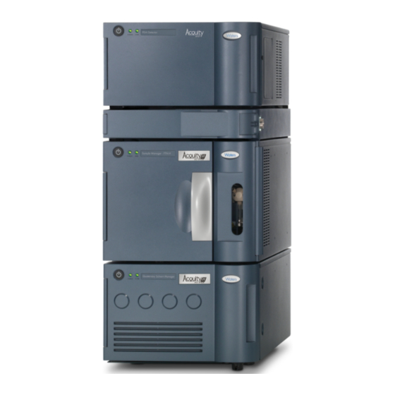
Waters ACQUITY UPLC Manuals
Manuals and User Guides for Waters ACQUITY UPLC. We have
6
Waters ACQUITY UPLC manuals available for free PDF download: Operator's Manual, Operator's, Overview And Maintenance Manual, Overview And Maintenance Manual, Care And Use Manual
Waters ACQUITY UPLC Operator's Manual (514 pages)
Brand:
Waters
| Category:
Laboratory Equipment
| Size: 6 MB
Table of Contents
Copyright Notice
2
Trademarks
2
Customer Comments
3
Contacting Waters
3
Safety Considerations
4
Considerations Specific to ACQUITY UPLC Instruments
4
Safety Advisories
4
Operating the ACQUITY UPLC Instruments
5
Applicable Symbols
5
Audience and Purpose
5
Intended Use of the ACQUITY UPLC System
5
Calibrating
5
Quality-Control
6
ISM Classification
6
ISM Classification: ISM Group 1 Class B
6
EC Authorized Representative
6
Table of Contents
7
System Overview
19
Instruments, Components, and Data Systems
20
Examples of Waters ACQUITY UPLC Systems
21
UPLC System Guidelines
22
ACQUITY UPLC Columns Calculator
23
Binary Solvent Manager
23
How the Binary Solvent Manager Works
24
Sample Manager
25
How Sample Flows
25
High Temperature Column Heater
26
Column Manager
26
Column Heater/Cooler
27
30-CM Column Heater/Cooler
27
Optional Sample Organizer
27
Detectors
28
TUV Detector
28
PDA Detector
28
ELS Detector
28
FLR Detector
29
Median Baseline Filter
29
Mass Spectrometers
29
SQ Detector
29
TQ Detector
29
Data Systems
30
Empower Software
30
Masslynx Software
30
Columns
30
Ecord Column Chip
31
Flexcart
31
For Additional Information
32
System Setup
33
Before You Begin
34
Tools
35
Assembling the Flexcart
35
Adjusting the Flexcart's Height
38
Locking the Flexcart in Place
39
Moving the Assembled Flexcart
41
Unpacking and Installing the Sample Organizer
41
Installing the Binary Solvent Manager
42
Installing the Sample Manager
42
Installing the HT Column Heater
43
Required Materials
43
Installing the Optional Column Manager
44
Installing the Optional Column Heater/Cooler
45
Installing the Detector
45
Installing the 30-CM Column Heater/Cooler
46
Plumbing the System
52
Installation Recommendations for Fittings
53
Plumbing a TUV Detector
54
Plumbing a PDA Detector
57
Plumbing an ELS Detector
57
Plumbing an FLR Detector
57
Plumbing the Binary Solvent Manager and Sample Manager
58
Plumbing the Column Manager
65
Plumbing the 30-CM Column Heater/Cooler
66
Routing System Drainage through the Flexcart
68
Installing the Column Stabilizer Assembly in an HT Column Heater
69
Required Materials
69
Installing the Column Stabilizer Assembly in a Column Heater/Cooler
72
Installing the Column In-Line Filter in a HT Column Heater
75
Installing the Column In-Line Filter in a Column Manager or Column Heater/Cooler
76
Installing the Column in an HT Column Heater
78
Installing the Column in a Column Manager or Column Heater/Cooler
81
Installing the Column in a System with a Mass Spectrometer
85
Connecting to the Solvent Supply
87
Making Ethernet and Signal Connections
89
Ethernet Connections
89
HT Column Heater Connections
89
30-CM Column Heater/Cooler Connections
90
Binary Solvent Manager I/O Signal Connectors
91
Sample Manager I/O Signal Connectors
93
TUV Detector I/O Signal Connectors
95
PDA Detector Signal Connectors
96
ELS Detector Signal Connectors
96
FLR Detector Signal Connectors
96
Signal Connections
96
Connecting to the Electricity Source
97
Calibrating the XYZ Mechanism Using the Teach Block
99
Preparing System Hardware
105
Powering on the System
105
Monitoring Startup Tests
107
Monitoring System Instrument Leds
107
Power LED
108
Status Leds
108
Enabling the Leak Sensors
110
Preparing the Binary Solvent Manager
111
Performing a Seal Wash Prime
111
Required Materials
112
Priming the Binary Solvent Manager
113
Priming a Dry Binary Solvent Manager
114
Priming a Wetted Binary Solvent Manager
116
Preparing the Sample Manager
119
Selecting Weak Wash and Strong Wash Solvents
119
Priming the Sample Manager
121
Washing the Sample Manager Needle
123
Characterizing the Needle Seal
125
Characterizing the Needle and Sample Loop Volumes
126
Using the Extended Puncture Needle
127
Loading Sample Plates in the Sample Manager
128
Selecting the Optimum Sample Injection Mode
129
Installing the Optional Sample Manager Shade
132
Preparing the Column Manager
134
Preparing the Sample Organizer
134
Initiating Communications
134
Loading Sample Plates
135
Displaying Sample Plate Information
139
Starting the TUV Detector
140
Conditioning the Column
143
Shutting down the System
144
Shutting down for Less than 24 Hours
144
Shutting down for more than 24 Hours
145
Running HPLC Methods on an ACQUITY UPLC System
146
System Considerations
146
Choosing Fittings
148
Configuring System Software
151
Configuring Empower Software
151
Starting Empower Software and Logging in
151
Selecting System Instruments
152
About the Binary Solvent Manager Control Panel
154
About the Sample Manager Control Panel
156
About the TUV Detector Control Panel
159
About the Column Manager Control Panel
161
Starting the ACQUITY UPLC Console from Empower Software
162
Configuring Masslynx Software
163
Starting the ACQUITY UPLC Console from Masslynx Software
164
Verifying System Operation
165
Preparing the System
166
Creating the Test Methods
169
Creating the Instrument Method
169
Creating the Sample Set Method
173
Performing the Gradient Performance Test
174
Maintaining the System
177
Maintenance Schedule
178
Spare Parts
181
Contacting Waters Technical Service
182
Locating System Serial Numbers
182
Maintenance Considerations
183
Safety and Handling
183
Proper Operating Procedures
184
Configuring Maintenance Warnings
184
Maintaining the Binary Solvent Manager
185
Resolving Binary Solvent Manager Leak Sensor Errors
186
Required Materials
187
Replacing the Binary Solvent Manager's Leak Sensor
191
Replacing the Mixer
195
Replacing the I Valve Actuator
197
Replacing the I Valve Cartridge
208
Replacing the In-Line Filter Cartridge on the I Valve Actuator
218
Replacing the Accumulator Check Valve
222
Required Materials
222
Replacing Solvent Filters
225
Cleaning the Air Filters in the Binary Solvent Manager Door
226
Replacing the Air Filters in the Binary Solvent Manager Door
227
Removing and Replacing the Primary Head Seals
228
Removing and Replacing the Accumulator Head Seals
246
Required Materials
246
Replacing the Primary Head Plungers
259
Required Materials
259
Replacing the Accumulator Head Plungers
279
Required Materials
279
Replacing the Vent Valve Cartridge
293
Required Materials
293
Replacing the Fuses
296
Cleaning the Instrument's Exterior
298
Maintaining the Sample Manager
298
Defrosting the Sample Compartment
298
Resolving Sample Manager Leak Sensor Errors
299
Replacing the Sample Manager's Leak Sensor
304
Replacing the Sample Needle Assembly
307
Calibrating the Needle Z-Axis
315
Characterizing the Needle Seal
316
Characterizing the Needle and Sample Loop Volumes
316
Replacing the Puncture Needle Holder
318
Required Materials
318
Replacing the Sample Loop
321
Replacing the Sample Syringe
325
Replacing the Wash Syringes
328
Modifying Sample Syringe Configuration Parameters
331
Replacing the Injection Valve Cartridge
332
Testing the Sample Manager Backpressure Regulator
335
Replacing the Fuses
335
Cleaning the Instrument's Exterior
337
Maintaining the HT Column Heater
338
Resolving HT Column Heater Leak Sensor Errors
343
Resolving HT Column Heater Leak Sensor Errors (Door Fully Opened)
343
Replacing the HT Column Heater's Leak Sensor
347
Replacing the HT Column Heater's Leak Sensor (Door Fully Opened)
350
Replacing the Column in the HT Column Heater
352
Replacing the Column Stabilizer Assembly in the HT Column Heater
353
Replacing the Frit in the HT Column Heater's In-Line Filter Unit
354
Maintaining the Column Manager and Column Heater/Cooler
356
Resolving Column Manager and Column Heater/Cooler Leak Sensor Errors
356
Replacing the Column Manager's or Column Heater/Cooler's Leak Sensor
360
Replacing the Column in the Column Manager
362
Replacing the Column in the Column Heater/Cooler
369
Replacing the Column Stabilizer Assembly in the Column Heater/Cooler
371
Replacing the Frit in the Column Manager's In-Line Filter Unit
372
Replacing the Filter in the Column Heater/Cooler's In-Line Filter Unit
375
Cleaning the Column Manager and Column Heater/Cooler
377
Exterior Surfaces
377
Interior Surfaces
378
Maintaining the TUV Detector
379
Resolving Detector Leak Sensor Errors
380
Replacing the Detector's Leak Sensor
384
Maintaining the Flow Cell
386
Cleaning the Flow Cell
388
Performing a System Acid Cleansing Flush
391
Replacing the Flow Cell
393
Replacing the Lamp
397
Required Material
397
Replacing the Fuses
399
Cleaning the Instrument's Exterior
401
Maintaining the Sample Organizer
401
Defrosting the Sample Organizer
401
Cleaning the Air Filter
401
Replacing the Fuses
402
Cleaning the Instrument's Exterior
404
Maintaining the 30-CM Column Heater/Cooler
405
Replacing the Fuses
405
Cleaning the Instrument's Exterior
406
Troubleshooting
407
Troubleshooting with Connections Insight
408
Proper Operating Procedures
409
Contacting Waters Technical Service
409
Locating System Serial Numbers
410
Solving Baseline Noise and Drift Problems
411
Binary Solvent Manager Troubleshooting
416
Power LED
416
Flow LED
417
Sample Manager Troubleshooting
420
Power LED
420
Run LED
420
Sample Organizer Troubleshooting
423
Power LED
423
Run LED
423
HT Column Heater Troubleshooting
427
Column Manager and Column Heater/Cooler Troubleshooting
427
Power LED
427
Run LED
427
TUV Detector Troubleshooting
430
Power LED
430
Lamp LED
430
Clearing Bubbles from the Flow Cell
430
PDA Detector Troubleshooting
433
Power LED
433
Lamp LED
434
ELS Detector Troubleshooting
438
Power LED
438
Lamp LED
438
FLR Detector Troubleshooting
439
Power LED
439
Lamp LED
440
Chromatography Troubleshooting
441
A Safety Advisories
449
Warning Symbols
450
Task-Specific Hazard Warnings
450
Warnings that Apply to Particular Instruments, Instrument Components, and Sample Types
451
Biohazard Warning
452
Caution Symbol
453
Warnings that Apply to All Waters Instruments
453
Electrical and Handling Symbols
460
Electrical Symbols
460
Handling Symbols
461
B Specifications
463
Binary Solvent Manager Specifications
464
Sample Manager Specifications
466
Sample Organizer Specifications
469
HT Column Heater Specifications
473
Column Manager and Column Heater/Cooler Specifications
475
30-CM Column Heater/Cooler Specifications
477
TUV Detector Specifications
479
C Solvent Considerations
483
Introduction
484
Preventing Contamination
484
Clean Solvents
484
Solvent Quality
484
Solvent Preparation
484
Water
485
Using Buffers
485
Buffered Solvents
485
Solvent Recommendations
486
General Solvent Guidelines
486
Solvents to Use
486
Solvents to Avoid
488
ACQUITY UPLC System Recommendations
488
Binary Solvent Manager Recommendations
490
Sample Manager Recommendations
490
Detector Recommendations
490
Solvent Miscibility
490
Using Miscibility Numbers (M-Numbers
491
Solvent Stabilizers
492
Solvent Viscosity
492
Wavelength Selection
493
UV Cutoffs for Common Solvents
493
Mixed Mobile Phases
493
Advertisement
Waters ACQUITY UPLC Overview And Maintenance Manual (141 pages)
Quaternary Solvent Manager
Brand:
Waters
| Category:
Laboratory Equipment
| Size: 5 MB
Table of Contents
General Information
2
Trademarks
2
Customer Comments
2
Contacting Waters
3
Safety Considerations
3
Safety Hazard Symbol Notice
3
Considerations Specific to the QSM
3
Electrical Power Safety Notice
4
Equipment Misuse Notice
4
Safety Advisories
4
Operating this Device
4
Applicable Symbols
5
Audience and Purpose
5
Intended Use of the QSM
6
Calibrating
6
Quality Control
6
ISM Classification: ISM Group 1 Class B
6
EC Authorized Representative
7
Table of Contents
8
1 Overview
12
Features
12
Gradient Smart Start
13
Auto•Blend Plus
13
Major Components
13
Pressure Flow Envelope
17
Pressure Transducer Overview
17
Flow Path through the Solvent Management System
17
2 Preparation and Operation
19
Installation Recommendations for Fittings
19
Assembling New Fittings
20
Stainless Steel (Gold-Plated) Fitting with Short Flats and 2-Piece Stainless-Steel Ferrule
21
Stainless Steel (Gold-Plated) Fitting with Long Flats and 2-Piece Stainless-Steel Ferrule
22
5/16-24 Fitting with Filter and Stainless Steel Lock Ring
24
Short 1/4-28 Fitting with Flangeless Ferrule and Stainless Steel Lock Ring Installed on 1/16-Inch OD Tubing
24
Long 1/4-28 Fitting with Flangeless Ferrule and Stainless Steel Lock Ring Installed on 1/8-Inch OD Tubing
25
Installing and Routing the Waste and Degasser Vent Tubing
25
Electricity Source
28
Connecting to a Wall Electricity Source
28
Connecting to a Cart's Electricity Source
28
Connecting Signal Cables
29
Input/Output Signal Connectors
31
Installing the Leak Sensor
31
Priming the Seal-Wash System
33
Priming the Solvent Manager
35
Priming a Dry Solvent Manager Via the Console
35
Priming a Dry Solvent Manager Using a Syringe
36
Washing the Plungers
38
Responding to a Leak Sensor Alarm
39
3 Maintenance
43
Contacting Waters Technical Service
43
Viewing Module Information
44
Recommended Maintenance Schedule
44
Recommended Maintenance Schedule for the Quaternary Solvent Manager
44
Spare Parts
45
Safety and Handling
45
Configuring Maintenance Warnings
46
Servicing the Air Filter in the Door
46
Replacing the Solvent Reservoir Filters
47
Replacing the Leak Sensor
48
Replacing the Inlet Manifold
51
Replacing the Low-Pressure Inlet Filters on the GPV Outlet
54
Replacing the 100-Μl Mixer/Filter
56
Installing or Replacing the Optional 250-Μl Mixer/Filter
57
Replacing the Vent-Valve Cartridge
59
Replacing the Optional Solvent Selection Valve Cartridge
61
Replacing the Accumulator Check Valve
63
Replacing the I Valve Actuator and Cartridge
66
Removing the I Valve Actuator
67
Removing the I Valve Cartridge from the Actuator
71
Installing the I Valve Cartridge on the Actuator
72
Installing the I Valve Actuator
76
Replacing the Primary Pump Head's Plunger and Seals
79
Moving the Plunger Backward
80
Removing the I Valve Actuator
81
Removing the Primary Pump Head
84
Removing the Pump Head Plunger
87
Removing the Pump Head Seals
89
Installing the New Pump Head Seals
92
Installing the New Pump-Head Plunger
96
Reinstalling the Primary Pump Head
98
Installing the I Valve Actuator
101
Replacing the Accumulator Pump Head's Plunger and Seals
105
Moving the Plunger Backward
106
Removing the Accumulator Pump Head
106
Removing the Pump Head Plunger
110
Cleaning the Exterior of the Equipment
125
A Safety Advisories
126
Warning Symbols
126
Specific Warnings
127
Notices
128
Bottles Prohibited Symbol
128
Required Protection
129
Warnings that Apply to All Waters Instruments and Devices
129
Warnings that Address the Replacing of Fuses
133
Electrical Symbols
135
Handling Symbols
136
B Specifications
137
QSM and Bioqsm Physical Specifications
137
QSM and Bioqsm Environmental Specifications
137
QSM and Bioqsm Electrical Specifications
137
QSM and Bioqsm Input/Output Specifications
138
QSM and Bioqsm Performance Specifications
139
QSM and Bioqsm Wetted Materials of Construction
141
Waters ACQUITY UPLC Overview And Maintenance Manual (126 pages)
Sample Manager Flow Through Needle
Brand:
Waters
| Category:
Industrial Equipment
| Size: 4 MB
Table of Contents
General Information
2
Trademarks
2
Customer Comments
2
Contacting Waters
3
Safety Considerations
3
Safety Hazard Symbol Notice
3
Considerations Specific to the SM-FTN
4
FCC Radiation Emissions Notice
4
Electrical Power Safety Notice
4
Equipment Misuse Notice
4
Safety Advisories
4
Operating the Device
5
Applicable Symbols
5
Audience and Purpose
6
Intended Use of the SM-FTN
6
Quality Control
6
EMC Considerations
6
Canada Spectrum Management Emissions Notice
7
ISM Classification: ISM Group 1 Class B
7
EC Authorized Representative
7
Table of Contents
8
1 Overview
12
Major Components
12
Flow Path through the System
16
Rθ Positioning Mechanism
16
Injection System
18
Injection Mechanics
18
Wash System
19
Thermal System
20
2 Preparation and Operation
21
Installation Recommendations for Fittings
21
Assembling New Fittings
22
1/4-28 Flangeless Fitting with Ferrule
23
1/4-28 Flangeless Fitting with 2-Piece Ferrule
24
One-Piece PEEK Fitting
24
Stainless Steel (Gold-Plated) Fitting with Long Flats and 2-Piece Stainless Steel Ferrule (V-Detail)
24
Ventilation Requirements
26
Stacking System Modules Without Interlocking Features
26
Stacking System Modules with Interlocking Features
27
Drainage System Requirements
28
Installing the Waste Tubing
28
Electricity Source
30
Connecting to a Wall Electricity Source
30
Connecting to a Cart's Electricity Source
30
Connecting Signal Cables
31
Input/Output Signal Connectors
33
Installing the Optional Leak Sensors
33
Installing the Optional Lower Leak Sensor
34
Installing the Optional Upper Leak Sensor
37
Calibrating the Needle
38
Purge Solvent
39
Wash Solvent
39
General Purge and Wash Solvent Guidelines
40
Priming the Sample Manager
41
Washing the Needle's Exterior
42
Stopping a Needle Wash Routine before It Finishes
42
Loading Sample Plates
43
Observing Vial and Plate Recommendations
46
Sample Chamber Considerations
47
Choosing Sample Needles
47
Choosing Extension Loops
47
Installing and Replacing Extension Loops
48
Modifying Needle and Extension Loop Configuration Parameters
50
Choosing the Sample Syringe
50
Modifying Sample Syringe Configuration Parameters
50
Choosing a Draw Rate for the Sample Syringe
51
Choosing the Needle-Placement Setting
51
Recovering Maximum Sample from Vials
52
Revising a Plate Type
53
Specifying an Air-Gap Volume
53
Load-Ahead Option
54
Loop-Offline Option
55
Determining When to Take the Needle and Extension Loop Offline
56
Choosing the Load-Ahead and Loop-Offline Options
57
Reducing Carryover
57
Auto Additions
58
Selecting Auto Dilution
58
Responding to a Leak-Sensor Alarm
58
Diagnostic Tests
61
3 Maintenance
63
Contacting Waters Technical Service
63
Viewing Module Information
64
Recommended Maintenance Schedule
64
Recommended Maintenance Schedule for the Sample Manager
64
Spare Parts
65
Safety and Handling
65
Configuring Maintenance Warnings
65
Replacing the Leak Sensor
66
Replacing the Seal
68
Replacing the Sample Needle and Needle Guide
84
Replacing the Sample Syringe
98
Cleaning the Injection Port
100
Replacing the Injection-Valve Cartridge
104
Cleaning the Exterior of the Equipment
107
A Safety Advisories
108
Warning Symbols
108
Specific Warnings
109
Notices
110
Bottles Prohibited Symbol
111
Required Protection
111
Warnings that Apply to All Waters Instruments and Devices
111
Warnings that Address the Replacement of Fuses
115
Electrical Symbols
117
Handling Symbols
118
B Specifications
119
SM-FTN and Biosm-FTN Physical Specifications
119
SM-FTN and Biosm-FTN Environmental Specifications
119
SM-FTN and Biosm-FTN Electrical Specifications
119
SM-FTN and Biosm-FTN Input/Output Specifications
120
SM-FTN and Biosm-FTN Performance Specifications
120
SM-FTN and Biosm-FTN Wetted Materials of Construction
126
Advertisement
Waters ACQUITY UPLC Operator's, Overview And Maintenance Manual (124 pages)
Photodiode Array And egPhotodiode Array Detector
Brand:
Waters
| Category:
Security Sensors
| Size: 1 MB
Table of Contents
Copyright Notice
2
Trademarks
2
Contacting Waters
3
Customer Comments
3
Safety Considerations
3
Considerations Specific to the ACQUITY Pda/Eλpda Detector
4
Operating the ACQUITY Pda/Eλpda Detector
5
Applicable Symbols
5
Audience and Purpose
5
Intended Use of the ACQUITY Pda/Eλpda Detector
5
Calibrating
6
Quality-Control
6
ISM Classification
7
EC Authorized Representative
7
Table of Contents
9
Overview
13
Detector Optics
13
Calculating Absorbance
16
Operating Principles of the Light-Guiding Flow Cell
17
Resolving Spectral Data
20
Measuring Light at the Photodiode Array
21
Computing Absorbance Data Points
24
Flow Cell Options
29
Before You Begin
30
Installing the Detector
31
Plumbing the Detector
33
Installing the Multi-Detector Drip Tray
37
Making Ethernet Connections
39
I/O Signal Connector
39
Connecting to the Electricity Source
40
Starting the Detector
41
Monitoring Detector Leds
43
About the Detector Control Panel
43
Shutting down the Detector
46
Shutting down for Less than 24 Hours
46
Shutting down for more than 24 Hours
46
Maintaining the Detector
48
Contacting Waters Technical Service
48
Maintenance Considerations
49
Proper Operating Procedures
49
Maintaining the Leak Sensor
51
Replacing the Detector's Leak Sensor
55
Maintaining the Flow Cell
57
Replacing the Lamp
68
Replacing the Fuses
71
Cleaning the Instrument's Exterior
72
Spectral Contrast Theory
73
Comparing Absorbance Spectra
73
Representing Spectra as Vectors
74
Spectral Contrast Angles
76
Undesirable Effects
79
Error Messages and Troubleshooting
83
Startup Error Messages
83
Error Messages Preventing Operation
86
Detector Troubleshooting
89
Safety Advisories
92
Warning Symbols
92
Caution Symbol
95
Warnings that Apply to All Waters Instruments
96
Electrical and Handling Symbols
102
Specifications
104
ACQUITY UPLC PDA Detector Specifications
104
ACQUITY UPLC Eλpda Detector Specifications
107
Solvent Considerations
110
Introduction
110
Solvent Miscibility
112
Wavelength Selection
114
Mobile Phase Absorbance
117
Waters ACQUITY UPLC Operator's, Overview And Maintenance Manual (144 pages)
Brand:
Waters
| Category:
Laboratory Equipment
| Size: 2 MB
Table of Contents
Copyright Notice
2
Considerations Specific to the Column Compartments
2
Table of Contents
3
Overview
5
Column Compartment Types
5
Preparing the Column Compartments
18
Installation Recommendations for Fittings
18
Installing the Standard Column Heater
21
Installing the 30-CM Column Heater
43
Installing the Column Manager
49
Installing One CM-Aux Module, in a Single-Stack Configuration
52
Installing Two CM-Aux Modules in a Multiple-Stack Configuration
58
Installing the ACQUITY 30-CM Column Heater/Cooler
86
Installing the Optional Column In-Line Filter
91
Installing the Column
93
Using the Column Compartments
102
Control Panels
102
Resolving Column Compartment Leak Sensor Errors
103
Maintaining the Column Compartments
114
Contacting Waters Technical Service
114
Maintenance Schedule
116
Maintenance Considerations
117
Configuring Maintenance Warnings
117
Replacing the Column Heater's Leak Sensor
118
Replacing the 30-CM Column Heater's Leak Sensor
123
Replacing the Column Manager's Leak Sensor
123
Replacing the Column Manager Switching-Valve Cartridge
126
Replacing the Column
129
Replacing the Active Preheater Assembly
131
Replacing the Column Stabilizer Assembly (CH-A Only)
137
Replacing the Frit in the In-Line Filter Unit
140
Waters ACQUITY UPLC Care And Use Manual (8 pages)
Oligonucleotide BEH C18 Column
Brand:
Waters
| Category:
Laboratory Equipment
| Size: 1 MB
Table of Contents
I. Introduction
1
Getting Started
2
A. Column Connectors
2
B. Column Installation
2
C. Column Equilibration
2
D. Procedure for Using New, Out-Of-Box Columns
2
E. Ecord Installation
2
F. Initial Column Efficiency Determination
2
G. Column QR Code
3
Column Use
4
Sample Preparation
4
B. Recommended Mobile Phases
4
Cleaning and Regeneration
5
C. Recommended Injector Wash Solvents
5
D. Ph Range
5
E. Pressure
5
F. Temperature
5
G. ACQUITY UPLC Mixer Options
5
H. Flow Rate
5
IV. Column Cleaning, Regeneration, and Storage
5
B. Storage
5
Ecord INTELLIGENT CHIP TECHNOLOGY
6
Manufacturing Information
6
Installation
6
A. Introduction
6
Additional Information
7
Cautionary Note
7
A. Band Spreading Minimization
7
Advertisement
Related Products
Waters ACQUITY Arc System
Waters ACQUITY UPLC H-Class Series
Waters ACQUITY Isocratic Solvent Manager
Waters ACQUITY Refractive Index Detector
Waters ACQUITY UPLC M-Class
Waters ACQUITY UPLC I-Class
Waters ACQUITY UPLC Xevo TQ-S micro IVD
Waters APGC
Waters Autospec Premier
Waters Alliance iS HPLC
Waters Categories
Laboratory Equipment
Security Sensors
Measuring Instruments
Control Unit
Water Pump
More Waters Manuals
Login
Sign In
OR
Sign in with Facebook
Sign in with Google
Upload manual
Upload from disk
Upload from URL