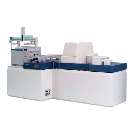
Sign In
Upload
Manuals
Brands
Waters Manuals
Laboratory Equipment
Autospec Premier
Waters Autospec Premier Manuals
Manuals and User Guides for Waters Autospec Premier. We have
1
Waters Autospec Premier manual available for free PDF download: Operator's Manual
Waters Autospec Premier Operator's Manual (354 pages)
Brand:
Waters
| Category:
Laboratory Equipment
| Size: 16.73 MB
Table of Contents
Copyright Notice
2
Trademarks
2
Customer Comments
3
Contacting Waters
4
Safety Considerations
4
Considerations Specific to the Autospec Premier
5
Solvent Leakage Hazard
5
Flammable Solvents Hazard
6
Pinch Hazard
7
High Temperature Hazard
8
High Voltage Hazard
8
Hazards Associated with Removing an Instrument from Service
9
High Magnetic Field Hazard
10
Safety Advisories
10
Operating this Instrument
11
Applicable Symbols
11
Intended Use of the Autospec Premier
11
Calibrating
12
Quality-Control
12
ISM Classification
12
ISM Classification: ISM Group 1 Class a
12
EC Authorized Representative
13
Table of Contents
15
Instrument Description
26
Sample Inlet
27
GC Sample Introduction
27
Probe Sample Introduction
28
Vacuum System
28
Masslynx Control System
29
Controls and Connections on the Front of the Instrument
30
A.C. Distribution Panel
30
Status Switch Panel
32
Controls and Connections on the Top of the Instrument
34
Probe Cooling Water Connections
34
Gas Flow Valves
34
Controls and Connections on the Rear of the Instrument
35
Cooling Water Connections
36
Magnet Power Connection
37
Electrical Power Outlets
38
Vacuum Connections
39
Gas Inlet Panel
40
Soft-Vent Control Panel
41
EPC Power Switch
42
Tuning the Instrument
43
Low Resolution Tuning
53
High Resolution Tuning
55
Additional Notes Concerning Manual Instrument Tuning
60
Ion Energy
60
Alpha Slit
61
Z4 Restrictor
61
Using the Autotune Facility
61
Scanning Techniques
65
Function Lists and the MS Method Editor
65
The MS Method Editor Toolbar
67
The Masslynx Experiment File
68
Editing the Function List
69
Setting the Maximum Retention Time
70
Setting up Scanning Functions
71
Magnet Scan Function
71
Voltage Scan Function
74
B/E (Product Ion) Function
76
B2/E (Precursor Ion) Function
79
Constant Neutral Loss (CNL) Function
82
MIKES Scan Function
85
NRMS Scan Function
86
SIR Function Editors
88
The Voltage SIR Function Editor
89
The SIR Mass Dialog Box
93
The MRM Function Editor
94
The MRM Mass Dialog Box
97
Example of VSIR Experiment Set up
98
Introduction
98
Creating the VSIR Function
99
Example of MRM Experiment Set up
103
Creating the MRM Function
103
Applying an Inter-Scan Current in FI Ionization Mode
107
Acquiring Data
110
Starting Data Acquisition
111
Starting Multiple-Sample Data Acquisition from the Masslynx Window
113
Automatic Quantification of the Sample List
117
Stopping Data Acquisition
119
Pausing Data Acquisition
120
Monitoring Data Acquisition
120
Viewing the Status of an Acquisition
120
Viewing a Chromatogram in Real-Time
121
Viewing a Spectrum in Real-Time
121
Acquiring Analog Data
122
Calibrating the Instrument
126
Calibration Files
126
Calibrating the Instrument for SIR Experiments
126
Calibrating the Instrument for MIKES and NRMS Experiments
129
Calibrating the Instrument for Scanning Experiments
129
Manually Correcting a Calibration
131
Editing the Calibration Parameters
133
Saving a Calibration
136
Applying the Calibration
136
Associating a Calibration File with an Experiment
137
Inlets and Probes
140
The GC Interface
140
Installing the GC Column
141
Required Materials
141
The Solids Sample Introduction Probe
142
Making the Probe Cooling Water Connections
143
Fitting the Probe Tip to the Probe
144
Loading Sample into the Sample Cup
144
Fitting the Sample Cup to the Probe Tip
146
Removing the Sample Cup from the Probe Tip
147
Inserting the Solids Sample Introduction Probe in the Ion Source
147
Removing the Probe from the Ion Source
151
Ramping the Probe Temperature
152
The Probe Control Dialog Box's Options Tab
152
The Probe Control Dialog Box's Ramps Tab
154
The Probe Control Dialog Box's Control Tab
156
Routine Maintenance
159
Maintenance Schedule
159
Safety and Handling
160
Vacuum Pump Maintenance
161
GC Interface Maintenance
161
Source Maintenance
163
Inner Source Chamber Assembly Maintenance
164
Required Materials
167
Withdrawing the Inner Source Chamber Assembly from the Source
168
Removing the Chamber Assembly from the Source Handle
172
Disassembling the Chamber Assembly
173
Cleaning Ion Burn from the Inner Source Chamber Assembly Components
179
Ultrasonically Cleaning the Chamber Assembly Components
181
Assembling the Inner Source Chamber Assembly
182
Fitting the Inner Source Chamber Assembly to the Source Handle
190
Inserting the Inner Source Chamber Assembly into the Outer Source
191
Degassing the Ion Source Assembly
195
Outer Source Maintenance
196
Required Materials
197
Removing the Outer Source Assembly from the Instrument
198
Disassembling the Outer Source
200
Disassembling the Re-Entrant Coupling Mechanism
214
Disassembling the Probe Contact Assembly
214
Disassembling the Inner Source Contact Support Assembly
216
Disassembling the Ion Chamber
218
Disassembling the Contact Rail Assemblies
220
Cleaning Ion Burn from the Outer Source Assembly Components
222
Ultrasonically Cleaning the Outer Source Assembly Components
223
Assembling the Re-Entrant Coupling Mechanism
224
Assembling the Probe Contact Assembly
224
Assembling the Inner Source Contact Support Assembly
225
Assembling the Ion Chamber
226
Assembling the Contact Rail Assemblies
230
Assembling the Outer Source Assembly
231
Fitting the Outer Source Assembly to the Instrument
237
Changing an Analyzer Ion Gauge
238
Measuring EI Sensitivity from the Solids Probe
240
Troubleshooting
247
Spare Parts
247
Safety and Handling
247
System Troubleshooting
248
Component Hardware Troubleshooting
248
Poor Peak Shape
252
Contacting Waters
252
A Safety Advisories
254
Warning Symbols
254
Task-Specific Hazard Warnings
254
Warnings that Apply to Particular Instruments, Instrument Components, and Sample Types
255
Burst Warning
255
Mass Spectrometer Flammable Solvents Warning
255
Mass Spectrometer Shock Hazard
256
Biohazard Warning
256
Chemical Hazard Warning
257
Caution Symbol
257
Warnings that Apply to All Waters Instruments
257
Electrical and Handling Symbols
260
Electrical Symbols
260
Handling Symbols
261
Preventing Contamination
263
Items Exposed to Solvent
263
Solvents Used to Prepare Mobile Phases
265
Starting up the Instrument
267
Shutting down the Instrument
272
D the Masslynx Tune Window
275
Opening the Masslynx Tune Window
275
The Tune Window File Menu
276
The Tune Window Edit Menu
277
The Tune Window Ion Mode Menu
277
The Tune Window Vacuum Menu
278
Monitoring the Instrument Vacuum
278
Controlling and Monitoring the Vacuum Pumps
279
Controlling Flight Tube Baking
283
The Tune Window Inlet Menu
285
The Tune Window Options Menu
285
Controlling the Display of Readback Windows
286
Viewing the Status of the Current Scan
286
Setting up the Instrument
287
The Instrument Setup Dialog Box's Magnet Tab
287
The Magnet Constant Utility Dialog Box
288
The Instrument Setup Dialog Box's Limits Tab
290
The Instrument Setup Dialog Box's y Focus Tab
291
The Instrument Set up Dialog Box Slits Tab
293
To Perform an Experiment Calibration
294
The Select Peaks of Interest Dialog Box
297
Verifying VSIR Experimental Resolution
298
Ramping the Probe Temperature
300
The Linked Scanning Utility
300
Configuring the Magnet and MIKES and NMRS Options
302
Viewing the Status Of, and Rebooting, the Instrument's Embedded PC
302
Selecting the Instrument Name
302
Customizing the Tune Window
303
The Tune Window Toolbar
303
The Tune Window Tuning Controls
305
The Source Tab
305
The EI Source Tab Parameters
306
The CI Source Tab Parameters
307
The LSIMS Source Tab Parameters
308
The FI Source Tab Parameters
309
The Lenses 1 Tab Parameters (for Analyzer Intensity
310
The Lenses 2 Tab Parameters (for Analyzer Resolution
311
The Inlets Tab
312
The AGHIS Tab Parameters
314
The Tune Window Instrument Controls
315
The Control 1 Tab Parameters
315
Specifying the Accelerating V Value
316
The Control 2 Tab Parameters and Controls
317
The Vacuum Tab
318
The Linked Scanning Tab
319
The MIKES And/Or NRMS Tab
320
The Tune Window Peak Display
321
Customizing the Peak Display
321
Opening the Peak Display Menu
321
Customizing the Colors and Numbers of Displayed Traces
322
Customizing the Peak Trace Line Appearance
323
Customizing the Peak Intensity Display
323
Customizing the Tune Window Peak Display Toolbar
324
Overview
329
Editing a Calibration Reference File
329
Calibration Reference Files
330
F Performance Specifications and File Types
334
Performance Specifications
334
File Types
334
Electron Impact (EI) Ionization
335
Chemical Ionization
336
Autospec Functionality
336
Source Assembly
337
Source Focus 1 and Focus 2 Lenses
337
Beam Center Lens
337
Z Deflect 1 Lens
337
First Field-Free Region Gas Cell
337
Source Slit
339
Y Deflect 1 Lens
339
Alpha Slit
339
Y Focus Lens
339
First ESA Assembly (ESA 1
339
Z Focus 2 Lens Assembly
339
Z Deflect 2 Lens
340
Z Focus 2 Lens
340
Rotate 2 Lens
340
Curve 2 Lens
340
Magnet
340
Z Focus 3 Lens Assembly
340
Curve 3 Lens
340
Rotate 3 Lens
341
Z Deflect 3 Lens
341
Z Focus 3 Lens
341
NRMS Gas Cell (Optional
341
MIKES Gas Cell (Optional
341
MIKES Slit (Optional
341
Second ESA Assembly (ESA 2
341
Collector Slit Plate Assembly
342
Z Restrictor 4 Plate
342
Rotate 4 Lens
342
Collector Slit
342
Dual Ion Detector
343
H File Types
346
File Types
346
Advertisement
Advertisement
Related Products
Waters ACQUITY Arc System
Waters ACQUITY UPLC H-Class Series
Waters ACQUITY Isocratic Solvent Manager
Waters ACQUITY UPLC
Waters ACQUITY Refractive Index Detector
Waters APGC
Waters ACQUITY UPLC M-Class
Waters ACQUITY UPLC I-Class
Waters Andrew+
Waters ACQUITY UPLC I-Class Series
Waters Categories
Laboratory Equipment
Security Sensors
Control Unit
Measuring Instruments
Water Pump
More Waters Manuals
Login
Sign In
OR
Sign in with Facebook
Sign in with Google
Upload manual
Upload from disk
Upload from URL