Sign In
Upload
Manuals
Brands
Videotek Manuals
Measuring Instruments
TVM9140PKG-EJ
Videotek TVM9140PKG-EJ Manuals
Manuals and User Guides for Videotek TVM9140PKG-EJ. We have
1
Videotek TVM9140PKG-EJ manual available for free PDF download: Installation And Operation Handbook
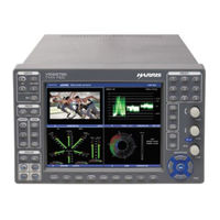
Videotek TVM9140PKG-EJ Installation And Operation Handbook (292 pages)
TVM Series Multi-Format 3Gb/s/HD-SDI/SD-SDI Monitor
Brand:
Videotek
| Category:
Measuring Instruments
| Size: 25 MB
Table of Contents
Table of Contents
7
Operator's Safety Summary
3
Ensuring Safety
3
Explanation of Symbols
4
Directives and Compliances
5
Waste from Electrical and Electronic Equipment (WEEE) Directive 2002/96/EC
5
Table of Contents
7
List of Figures
18
Section 1 ♦ Introduction
25
Product Description
25
Standard Features
25
TVM Series Configuration
26
Audio Options (Supports One)
26
Console
26
Graphics Engines (Requires One)
26
Video Input Options (Supports Two)
28
Auxiliary Options
29
Figure 2-1. Mounting the TVM in a Rack Using the DRC-2A
29
TVM Package Configurations
29
List of Figures
29
Video Standards Supported
31
Figure 2-2. TVM Back Panel Connectors
31
Table 1-1. Options and Supported Video Formats
31
Table 1-2. 3Gb/S Formats
32
Table 1-3. Dual Link Formats
33
Figure 2-3. TVM Dedicated PC Connection
34
Table 1-4. HD Formats
34
Table 1-5. SD Formats
34
Front and Back Panels
35
Figure 2-4. TVM Network PC Connection
35
Service and Support
36
Figure 2-5. Multiple Tvms Network PC Connection
36
Section 2 ♦ Installation
37
Inspecting the Shipment
37
Figure 2-6. Connecting the RCU 1000 Remote Control Panel to Multiple TVM/VTM Series Units
37
Rack Mounting the TVM
38
Table 2-1. Parts Required to Rack Mount the TVM Using the DRC-2A
38
Figure 3-1. TVM Series Front Panel
39
Connecting the TVM
40
Figure 3-2. Sample Multi-Display
40
Table 2-2. Description of Back Panel Connectors
40
Ethernet Setup
42
Figure 3-3. Selecting a Pane
42
Configuring the TVM for Remote Control
44
Configuring the TVM/VTM with the RCU 1000 Remote Control
44
Section 3 ♦ General Operation
47
Terms
47
Introduction to Operating the TVM Series
47
Figure 3-4. Sample Quad Diagram
47
Figure 3-5. Full-Screen Display Diagram
47
Types of Controls
48
Front Panel Illumination
48
Table 3-1. Description of Front Panel Controls Illumination
48
Sleep Mode
49
Figure 3-6. Waveform Display Diagram
49
Selecting a Pane
50
Full-Screen Display Selection
50
Selecting an Input for a Pane
50
Format Mismatch Message
51
Linking Panes
51
Selecting the Function for the Pane
51
Function Not Allowed Message
51
Option Not Installed Message
51
Navigating the Pane Setup Menu
51
Figure 3-7. RGB and YC B C R Graticule
51
External Reference
52
EXT Setup
53
Pane Overview
53
Table 3-2. EXT Menu
53
Icons
54
Main Title Bar
54
Status Bar
55
The Waveform Display
55
Table 3-3. Description of Icons
55
Table 3-4. Video Formats and Units of Measure
55
Table 3-5. Video Formats and Critical Amplitude Limits
56
Table 3-6. Description of Waveform Display Diagram
56
Moving the Waveform Using the Setup Knobs
58
Waveform Front Panel Selections
58
Sweep Buttons
59
Gain Buttons
61
Placing the Waveform Display in Line Select Mode
62
Waveform Cursor Selections
62
Waveform Pane Menu Selections
63
Table 3-7. Waveform (Analog) Menu Structure
64
Table 3-8. Waveform (SD-SDI) Menu Structure
64
Table 3-9. Waveform (3Gb/Hd-SDI) Menu Structure
65
Blanking (SDI Signals Only)
66
Filter Selection
66
HD or SD Format
66
Parade and Overlay Selections
66
Table 3-10. Input and Display Format Relationship
66
Center Waveform
67
Component Sequence (SDI Signals Only)
67
Waveform Setup
67
Utilizing the EYE Display (TVM-VTM-EYE-H, TVM9100PKG-EH, TVM9100PKG-ES, TVM9140PKG-EH, TVM9140PKG-ES)
67
Table 3-11. Description of Eye Pattern Display Diagram
68
Eye Pattern Observation
69
Eye Pattern Rise Time
70
Horizontal Magnification and Zoom in Eye Pattern Mode
70
Jitter Meter and Eye Pattern Correlation
70
Table 3-12. Horizontal Magnification Conditions
70
Eye Pattern Cursor Selections
71
Eye Pattern Pane Menu Selections
72
Jitter High Pass Filter (HPF) Selection
72
Table 3-13. Eye SD-SDI Pane Menu Structure
72
Table 3-14. Eye HD-SDI Pane Menu Structure
72
Eye Pattern Setup
73
Trigger Mode
73
Utilizing the EYE and Jitter Displays (TVM-VTM-JEM, TVM9100PKG-EJ, and TVM9140PKG-EJ)
73
Table 3-15. Description of TVM-VTM-JEM Option Back Panel Connectors
74
Table 3-16. Description of Eye Pattern Display Diagram
76
Table 3-17. Description of Jitter Waveform Display Diagram
77
Table 3-18. Description of Frequency Waveform Display Diagram
78
Eye Pattern Measurement Parameters/Considerations
80
Eye Pattern Parameters
80
Horizontal Magnification and Zoom in Eye Pattern Mode
80
Jitter Meter and Eye Pattern Correlation
80
Eye Pattern Cursor Selections
81
Table 3-19. Horizontal Magnification Conditions
81
Eye Pattern and Jitter Pane Menu Selections
83
Table 3-20. Eye SD-SDI Pane Menu Structure
83
Table 3-21. Eye HD-SDI Pane Menu Structure
83
Table 3-22. Jitter Waveform Pane Menu Structure
83
Eye Pattern Setup
84
Jitter High Pass Filter (HPF) Selection
84
Jitter Waveform Mode
84
Trigger Mode
84
Utilizing the Vector Display
85
Controlling the Vector
90
Gain Buttons
90
Placing the Vector Display in Line Select Mode
92
Vector Cursor Selections
92
Vector Pane Menu Selections
93
Scaled to Composite (SD and HD Only)
94
Standard
94
Gamut Display
95
Vector Position (Centering the Vector)
95
Vector Setup
95
Composite Gamut
97
RGB Gamut Display
98
Gamut Zoom
100
Placing the Gamut Display in Line Select Mode
100
Color Space
101
Gamut Pane Menu Selections
101
Gamut Setup
101
Picture Display
101
Picture Pane Menu Selections
103
Closed Caption
104
Delay
104
Gamut Highlighting
104
Native Mode
104
Picture Setup
104
Timing Display
106
Reference Selection
108
Things to Remember When Using the Timing Display
108
Timing Mode
108
Timing Pane Menu Selections
108
Alarm Display
109
Alarm Log Display
109
Alarm Status Display
111
Alarm Log and Status Pane Menu Selections
113
Alarm Log Display
113
Display
113
Audio Alarms
114
Mute Alarms
114
Video Alarm Analog
114
Video Alarm Digital
114
Audio Display
114
Audio Scales
115
Vertical Audio Displays
115
Cinesound Display
121
Loudness Display
123
Audio Input Check
125
Audio Menu Selections
125
Expanding the Audio Display
125
Lissajous
125
Audio Setup
126
V2A Timing Display (TVM-A3-OPT V2A Only)
126
Option Display
126
Display
127
Option Setup
127
Dolby Metadata Display (Option Dependent)
128
Video Metadata
130
Xds
132
Crc
133
Teletext
133
ASI (Option TVM-VTM-ASI Only)
136
DVB Stream Formats
137
ASI Menu Selections
138
Bandwidth and Trending Screen
138
Embedded Audio Data
140
Multi-Screen Display Selection
140
TVM Classic
141
Data Analyzer Display (HD-SDI and SD-SDI Only)
143
Data Display Pop-Up Menu
145
Pixel Cursor
145
Data Display Format
146
Navigation Mode
146
Pixel Group Display
146
Trigger on Alarm
146
Data Search (SD-SDI and HD-SDI Only)
147
Custom Data Search
148
Data Analyzer Display (TVM-VTM-3GB Option)
148
Timing Custom Display
151
WFM/VEC Only Display (Dual-Screen Display)
151
3Gb/S WFM/VEC Mode (with TVM-VTM-3GB Only)
152
The 3 Gb/S WFM/VEC Mode Display
152
Using the TVM-VTM-3GB as a Monitor
153
Using the TVM-VTM-3GB as a Test Signal Generator
153
Preset *8 (Factory Preset)
154
Preset Setup Menu
154
Presets
154
Storing Presets
154
Clear Preset
155
Name Preset
155
Setup
155
Capturing a Display
156
Capturing Display Information
156
Clear Captured Data
156
Clear Captured Frame
156
Freeze and Freeze + Live Mode (SD-SDI and HD-SDI Only)
157
Section 4 ♦ Global Setup Menu Functions
159
Navigating the Setup Menu
159
Setup Menu and Alarm Tables
160
Video Format Menu
160
Video A, B, C, or D Format
161
Video A, B, C, or D Structure
161
Attack
165
DC Restore (Analog Option Required)
165
Digital Waveform Graticule
165
Error Highlighting
165
Eye Intensity
165
NTSC Pedestal (or 7.5 IRE Setup)
165
PAL Waveform Scale
165
Persistence
165
Waveform Contrast
165
Waveform Intensity
165
Attack
166
Color Plot
166
Data Error Persistence
166
Gamut Contrast
166
Persistence
166
SDI I/Q Lines
166
Thumbnail
166
Closed Caption Display
167
Markers
167
(Closed Caption) Size
168
Anamorphic
168
Brightness
168
Contrast
168
Teletext Page
168
Time Code
168
Xds
168
(Picture) Color
198
Blue Gun
198
Green Gun
198
Red Gun
198
Vbi Mask
198
Monitor Out/Generator A-B and C-D
198
Display Setup
199
Display Colors
199
Cursor Intensity
200
Graticule Intensity
200
Monitor
200
XGA Freeze
200
LCD Backlight
201
Communications Setup
201
IP Configuration
201
RCU Port
201
GPI Input Function and GPI Alarm Names
202
GPI Output Function
203
GPI Alarm Reporting Setup
204
Router Port
204
Unit ID
204
System Setup Menu
204
Panel and Preset Lockout
204
Clock Display
207
Set Time
207
Aural Alert
208
Control Illumination
208
Time Code Input
208
Diagnostics (System Fault Log)
209
File Navigator
209
Flash Update from USB
210
Power Requirements
246
Standard Accessories
247
Cambridge Broadband Ltd. Copyright Notice (BSD)
257
Sun Microsystems, Inc. Copyright Notice (BSD)
258
Sparta, Inc. Copyright Notice (BSD)
259
Cisco/Buptnic Copyright Notice (BSD)
260
Fabasoft R&D Software Gmbh & Co. KG Copyright Notice (BSD)
261
GNU General Public License
262
The GNU V2 License
262
Version 2, June 1991
262
Terms and Conditions for Copying, Distribution and Modification
263
No Warranty
266
GNU Lesser General Public License
267
GNU Lesser Public License
267
Version 2.1, February 1999
267
Terms and Conditions for Copying, Distribution and Modification
269
No Warranty
274
Appendix D ♦ Glossary
275
Index
285
Advertisement
Advertisement
Related Products
Videotek TVM9140PKG
Videotek TVM9140PKG-3GB
Videotek TVM9140PKG-A
Videotek TVM9140PKG-EH
Videotek TVM9140PKG-SD
Videotek TVM9140PKG-ES
Videotek TVM9100PKG
Videotek TVM9100PKG-A
Videotek TVM9100PKG-EH
Videotek TVM9100PKG-SD
Videotek Categories
Monitor
Extender
Measuring Instruments
More Videotek Manuals
Login
Sign In
OR
Sign in with Facebook
Sign in with Google
Upload manual
Upload from disk
Upload from URL