Sign In
Upload
Manuals
Brands
Sony Manuals
VCR
10001
Sony 10001 Manuals
Manuals and User Guides for Sony 10001. We have
8
Sony 10001 manuals available for free PDF download: Maintenance Manual, Operation Manual, Installation Manual
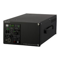
Sony 10001 Maintenance Manual (392 pages)
HD CAMERA CONTROL UNIT
Brand:
Sony
| Category:
Control Unit
| Size: 15.67 MB
Table of Contents
7
Table of Contents
13
Manual Structure
13
Purpose of this Manual
13
Related Manuals
15
1 Service Overview
15
Checking the ROM and Software Version
15
Rom
15
Software
16
Power Cord
17
Connectors and Cables
17
Connector Input/Output Signals of HDCU2500
20
Connector Input/Output Signals of HKCU2007
20
Connector Input/Output Signals of HKCU1001
21
Connector Input/Output Signals of HKCU1003
22
Wiring Diagrams for Cables
22
Connection Connectors/Cables
23
Note in Connecting CAMERA Connector
24
Location of Printed Circuit Boards
25
Outside Dimensions
26
Functions of Onboard Parts
26
Description of Onboard LED Indicators
29
Functions of Onboard Switches
32
Functions of Onboard Potentiometers
34
Service Tools/Measuring Equipment List
34
Service Tools
34
Measuring Equipment
35
Cautions When Replacing the Lithium Battery
35
Replacing Procedure
36
Replacing the Flexible Card Wires
37
Option Board Installation Position
37
When Installing Option Model
38
Installing the Option Board
38
Front Side (HKCU2007)
39
Rear Side (HKCU2007)
40
Front Side (HKCU1001/1003)
41
Rear Side (HKCU1001/1003)
42
Writing and Rewriting the PLD Internal Data
42
E-Production System Has the Advantages Shown below
44
Circuit Protective Devices
44
Fuse
44
Thermistor
47
Cleaning of Connector/Cable
47
When the Optical Connector Cleaner (Commercially Available) Is Available
48
When the Optical Connector Cleaner (Commercially Available) Is Not Available
52
Circuit Description
52
Front Boards
53
Rear Boards
54
Hkcu2007
54
Hkcu1001
55
Hkcu1003
56
Lead-Free Solder
57
2 System Setup
57
System Connection
58
Example of Connection
59
Standard 3G/HD/SD System
60
Standard 3G/HD/SD System with SD Analog Encoder (HKCU1001)
61
Standard 3G/HD/SD System with 3G Signal Interface (HKCU2007)
62
Setting the System Formats
62
Setting the Multi-Format
62
Setting the Reference Input
63
Audio System
63
Setting the Intercom System
65
Microphone Setting
67
System Settings
67
Tally System Setting
67
Camera Number Setting
68
Connecting the Control, Intercom, Tally and Audio Signals
69
Video Signal System
69
Input/Output Signal Selection
69
Signal Phase Adjustment
70
Aspect Ratio Setting for Down-Conversion
72
VBS Signal Level Adjustment (Only When HKCU1001/1003 Is Installed)
73
Waveform Monitor Signal Level Adjustment (Only When HKCU1001/1003 Is Installed)
74
Stair Case Signal Adjustment Procedure (Only When HKCU1001/1003 Is Installed)
75
Picture Monitor Signal Level Adjustment (Only When HKCU1001/1003 Is Installed)
76
RETURN Input Signal
77
3 Menu Settings
77
Preparations
77
Display/Hide the Status Screen
77
Starting/Exiting the Maintenance Mode
78
Memory Stick
79
Status Display
79
Camera Settings
80
Settings of Entire System
80
Status of Internal Boards
80
Camera System Diagnostics
81
Network Diagnostics
82
Board Diagnostics
83
Status of the Board Inserted in Slot
84
SDP Board Diagnostics
85
Camera Board Status
85
Version Information of Roms in each Unit
86
SYSTEM OPERATION Menu
92
CCU CONFIGURATION Menu
103
NETWORK SETTINGS Menu
105
VE OPERATION Menu
115
MAINTENANCE Menu
119
4 Replacement of Main Parts
119
General Information for Parts Replacement
119
Index
121
Basic Knowledge
122
Power Supply Unit
122
Power Block Assembly (D00)
123
DC Fan
125
RE-274 Board
126
PS-778D00 Board
128
Notes on Disassembling the Power Block Assembly (D00)
131
Front Panel
131
Removal and Installation of Front Panel
131
CN-3451 Board
132
AU-340 Board / LE-377 Board
134
Rear Panel
134
Removal and Installation of Rear Panel Assembly
134
SDP-17 Board
137
Plug-In Board
137
Installing/Removing Plug-In Boards on the Front Side
138
Installing/Removing Plug-In Boards and Blank Panels on the Rear Side
139
Main Frame
139
HIF-62 Board
140
CN-2675G Board
141
CN-2676 Board
142
CN-2677G Board
143
VIF-52 Board
144
ADO-12 Board
145
CNB-29A Board
146
MB-1181 Board
149
5 Electrical Alignment
149
Preparations
149
Equipment Required
149
Notes on Adjustments
150
Connection of Equipment
150
Initialization Settings
152
Audio System Adjustment
152
RTS Intercom Adjustment
155
Video/Reference Signal System Adjustment
155
27 Mhz VCO Free-Running Adjustment
156
Prompter 1/2 Level Adjustment
157
STAIR CASE Adjustment
159
SD Signal System Adjustment
159
VBS Output Level Adjustment
159
PIX Output Level Adjustment
160
WF Output Level Adjustment
163
6 Spare Parts
163
Note on Repair Parts
164
Exploded Views
169
Electrical Parts List
260
Supplied Accessories
261
7 Block Diagrams
261
Overall
265
8 Schematic Diagrams
265
Ado-12
276
Avp-15
319
Hif-62
324
Ps-778D00
339
Sdi-99
344
Sdp-17
351
Vda-64A
352
Vda-64B
353
Vif-52
356
Frame Wiring
357
9 Board Layouts
357
Ado-12
Advertisement
Sony 10001 Maintenance Manual (246 pages)
Brand:
Sony
| Category:
VCR
| Size: 3.53 MB
Table of Contents
5
Table of Contents
9
Contents
9
Manual Structure
9
Purpose of this Manual
10
Related Manuals
10
Trademarks
11
1 Installation
11
Installation Procedure
11
Supplied Accessories
12
Operating Conditions
12
Power Supply
12
Voltage and Power Requirements
12
Power Cord
13
Installation Space
14
Rack Mounting
19
Matching Connectors and Cables
20
Signal Inputs and Outputs
24
Switch Settings on Connector Panel
25
Switch and Shorting Plug Settings on PC Boards
25
Board
29
Board
31
TBC-23A Board
32
Board
34
Switching Search Dial Mode
35
Reference System
36
Settings and Adjustment When External Equipment Is Connected
36
Settings for Time Code
36
VTR Constant Values Settings of Editor
37
System Phase Alignment
37
Setup Menu Settings
39
2 Service Overview
39
Notes on Power Supply Block
39
Note on Resetting the Circuit Breaker
39
Cleaning When the Heads Are Clogged
40
Removing/Reattaching Cabinet
40
Upper Lid, Side Panels, and Bottom Plate
41
Control Panels
42
Connector Panel Assembly
43
Power Supply Panel Assembly
43
Removing/Reattaching Plate MD Assembly
44
Removing/Reattaching Cassette Compartment
45
Removing/Reattaching Lower Control Panel Assembly
46
Circuit Function
48
Location of Main Parts
51
Main Mechanical Part Locations
52
Function and Location of Sensors
54
System of Cassettes
56
Function of Leds on Circuit Boards
60
Taking out the Cassette in Tape Slacking
61
Removing/Reattaching Plug-In Boards
62
Fixtures and Adjustment Equipment List
62
Fixtures
64
Equipment for Adjustment
65
Isr
66
Battery for Memory Backup
67
Setup Menu (F-Series)
67
Menu Operation
68
F-Series Items
71
3 Error Message
71
Overview of Error Message
73
Details of Error Messages
91
4 Maintenance Mode
91
Overview of Maintenance Mode
96
TAPE Maintenance Mode (M0)
96
Overviews
104
SERVO CHECK Mode (C00-03)
119
ANALOG DT CHECK Mode (C04)
120
RF CHECK Mode (C1)
127
AUDIO/VIDEO CHECK Mode (C2)
134
BETACAM PB CHECK Mode (C3)
136
SERVO ADJUST Mode (A00-01)
143
ANALOG DT ADJUST Mode (A02)
148
RF ADJUST Mode (A1)
156
AUDIO/VIDEO ADJUST Mode (A2)
165
BETACAM PB ADJUST Mode (A3)
168
MECHANISM ADJUST Mode (A4)
169
Error Logger Display Mode (M2)
169
Outline
170
Display Mode
172
Setting Mode
174
OTHERS CHECK Mode (M3)
174
Outline
175
ROM VERSION Display Menu (M30)
175
SERIAL NUMBER Display Menu (M31)
176
RS-232C STATUS Display Menu (M32)
177
MEMORY CHECK Display Menu (M35)
177
HOUR METER RESET Menu (M36)
178
METER HEAD ROOM Setup Menu (M37)
178
50PIN DATA ASSIGN Mode (M39)
182
Setup Maintenance Mode (M4)
182
Outline
182
EXTENDED MENU Display Selection Menu (M40)
183
RESET ALL SETUP Executing Menu (M49)
185
5 Periodic Maintenance and Inspection
185
Periodic Maintenance
185
Index
186
Periodic Replacement and Check Item Table
188
Hours Meter
189
Cleaning
189
Cleaning Using Cleaning Tape
189
General Information for Cleaning Using Cleaning Cloth
191
Tape Running Surface of Upper Drum and Video Heads Cleaning
192
Tape Running Surface of Lower Drum and Lead Surface Cleaning
193
Stationary Heads Cleaning
194
Tape Running System and Tape Cleaner Cleaning
195
Fan Motors Cleaning
196
Cassette Compartment and Cassette Supports Cleaning
197
Video Head Tip Protrusion Check
197
Head Tip Protrusion Measurement
200
Brush Slip Ring Assembly Removal/Reinstallation
201
6 Spare Parts
201
Notes on Repair Parts
202
Exploded Views
204
Plug-In Boards
205
Packing Materials and Supplied Accessories List
205
Power Cords List
206
Fixtures List
207
Appendix A Outline of Format
207
A-1. Outline
207
A-2. Recording Format
211
A-3. Head Configuration
212
A-4. Signal Processing
212
A-4-1. Compression System of Video Signal
212
A-4-2. Outline of Signal Processing
215
Appendix B Setting Check Sheet
Sony 10001 Maintenance Manual (158 pages)
DIGITAL VIDEO SWITCHER
Brand:
Sony
| Category:
Switch
| Size: 2.25 MB
Table of Contents
5
Table of Contents
7
Manual Structure
7
Purpose of this Manual
7
Related Manuals
8
Contents
9
1 Service Overview
9
Dvs-7200A
9
Removal and Installation of Front Panel
10
Location of Main Parts
12
Inserting/Pulling out of Plug-In Boards
13
Capacitor for Data Backup
14
Spare Parts
15
Control Panel
15
Opening and Closing of Panel
16
Turning On/Off the Power Switch
17
Removal of Exterior Parts
18
Location of Main Parts
23
Installation and Removal of Boards
51
Replacement of Backup Memory IC
52
Spare Parts
55
2 Replacement of Main Parts
55
Dvs-7200A
55
Replacement of Fan on the Rear Panel
57
Replacement of Power Unit
58
Control Panel
58
Replacement of Rotary Encoder
61
Replacement of Fader
62
Replacement of el Display
64
Replacement of FDD (Floppy Disk Drive) Unit
66
Replacement of Power Unit
69
3 Troubleshooting (Control Panels)
69
Self Diagnostics Mode (BKDS-7015)
70
Switch Settings on the CPU-246 Board and Leds Description (BKDS-7015)
78
Troubleshooting (BKDS-7015)
78
Tools and Equipment Required for Troubleshooting
80
Connecting the Test Terminal with Connector to this Unit
81
Starting of the Self Diagnostics Mode
83
Test Procedures
101
Ending the Self Diagnostics Mode
102
Self Diagnostics Mode (BKDS-7025/7026)
103
Switch Settings on the CPU-263 Board and Leds Description (BKDS-7025/7026)
111
Troubleshooting (BKDS-7025/7026)
111
Tools and Equipment Required for Troubleshooting
113
Connecting the Test Terminal with Connector to this Unit
114
Starting of the Self Diagnostics Mode
116
Test Procedures
135
Ending the Self Diagnostics Mode
137
4 Periodic Check and Maintenance
137
Cleaning
137
Front Panel
137
Fans
138
Track Ball (BKDS-7031)
139
5 Overall Block Diagrams
142
Dvs-7200A (2Me System)
142
Dvs-7200A (2.5Me System)
145
Bkds-7015
150
Bkds-7025/7026
Advertisement
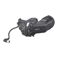
Sony 10001 Maintenance Manual (74 pages)
HD ELECTRONIC VIEWFINDER
Brand:
Sony
| Category:
Camera Accessories
| Size: 3.6 MB
Table of Contents
3
Table of Contents
5
Manual Structure
5
Purpose of this Manual
5
Relative Manual
7
1 Service Overview
7
Check Item before Starting Maintenance
7
Check Item after Completing Maintenance
7
Board Layouts
8
Circuit Description
9
Board
10
Board
13
Board
13
SW-1437 Board
14
Replacing the Main Parts
14
Replacing the LCD Module
17
Replacing the Protection Glass and Glass Cushion
19
Replacing the Anti-Glare Sheet
22
When the LCD Module Is Replaced
22
When the PR-312 Board Is Replaced
22
Voltage Check of the RE-257 Board
23
How to Measure Luminance
24
Rewriting the PLD Internal Data
26
Notes on Repair Parts
26
Lead-Free Solder
27
Recommended Replacement Parts
28
Viewfi Nder Rotating Torque Adjustment
30
When Rotation of Viewfi Nder Becomes Diffi Cult
31
2 Spare Parts
31
Notes on Repair Parts
32
Exploded Views
37
Electrical Parts List
49
Packing Materials & Supplied Accessories
51
3 Block Diagrams Overall
51
Overall Block
53
4 Schematic Diagrams
68
Frame Wiring
Sony 10001 Maintenance Manual (98 pages)
Brand:
Sony
| Category:
Camcorder
| Size: 2.69 MB
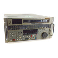
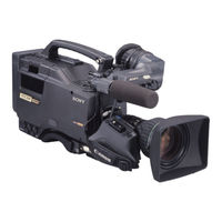
Sony 10001 Operation Manual (54 pages)
digital videocassette player
Brand:
Sony
| Category:
Media Player
| Size: 0.34 MB
Table of Contents
3
Table of Contents
5
Outline of the DVW-522/522P
6
Chapter 1
6
Features
6
Digital BETACAM Format
7
Advanced Playback Functions
8
Ease of Operation
9
Optional Accessories
11
Control Panel
12
Upper Control Panel
13
Lower Control Panel (Tape Transport Section)
14
Lower Control Panel (Search Operation Section)
15
Lower Control Panel (Time Code Section)
17
System Set-Up Panel
19
Connector Panel
21
Chapter 2
21
Chapter 3
21
Setting up the VTR
21
Connecting External Equipment
22
Set-Up Menu
22
Items that Require Setting for Operations
27
Changing Menu Settings
34
Superimposed Characters
36
Handling Cassettes
36
Recommended Cassettes
36
Inserting and Ejecting Cassettes
39
Preparing for Playback
39
Setting Switches
40
Selecting Time Data to be Displayed
41
Playback
41
Normal-Speed Playback
42
Variable-Speed Playback in Jog/Shuttle/Variable Modes
45
Capstan Override Playback
47
Head Cleaning
48
Moisture Condensation
49
Chapter 4
49
Chapter 5
49
Appendixes
52
Index
Sony 10001 Installation Manual (50 pages)
DIGITAL VIDEOCASSETTE RECORDER DIGITAL VIDEOCASSETTE PLAYER
Brand:
Sony
| Category:
VCR
| Size: 0.66 MB
Table of Contents
5
Table of Contents
6
Manual Structure
6
Purpose of This Manual
6
Related Manuals
7
Installation
7
Installation Procedure
7
Supplied Accessories
8
Operating Conditions
8
Power Supply
8
Voltage and Power Requirements
8
Power Cord
9
Installation Space
10
Rack Mounting
15
Matching Connectors and Cables
16
Signal Inputs and Outputs
20
Switch Settings On Connector Panel
21
Audio-Related Shorting Plug Settings
25
Displaying Setup Extended Menu
26
Switching Search Dial Mode
27
Reference System
27
In DNW-75/75P
28
In DNW-65/65P
28
Settings and Adjustment When External Equipment Is Connected
28
Settings for Time Code (DNW-75/75P Only)
28
VTR Constant Values Settings of Editor
29
System Phase Alignment
29
Setup Menu Settings
30
Removing/Reattaching Plug-In Boards
31
Taking Out the Cassette in Tape Slacking
33
Appendix A Setting Check Sheet
Sony 10001 Installation Manual (28 pages)
A/V MULTIPLEXER BOARD, A/V DEMULTIPLEXER BOARD
Brand:
Sony
| Category:
Multiplexer
| Size: 0.35 MB
Table of Contents
3
Table of Contents
4
Manual Structure
4
Purpose of this Manual
4
Contents
4
Related Manual
5
Installation
5
Installation of Boards
7
Information of BKPF-105A
7
Location and Function of Connectors
7
Connectors and Cables
8
Location and Function of Switches/Leds
11
Isr
12
Information of BKPF-106A
12
Location and Function of Connectors
12
Connectors and Cables
13
Location and Function of Switches/Leds
15
Isr
16
Information of BKPF-205
16
Location and Function of Connectors
16
Connectors and Cables
17
Location and Function of Switches/Leds
20
Isr
21
Information of BKPF-206
21
Location and Function of Connectors
21
Connectors and Cables
22
Location and Function of Switches/Leds
Share and save
Advertisement
Related Products
Sony 1080i
Sony 1000RF - CDX CD Player
Sony 1001K - PSP Game Console
Sony Multiscan 100ES
Sony Multiscan 100SF CPD-100SF
Sony Multiscan 100sx
Sony Multiscan 100 sf
Sony 1000XM3
Sony 100001
Sony Digital 1000
Sony Categories
Laptop
Camcorder
CD Player
TV
Car Receiver
More Sony Manuals
Login
Sign In
OR
Sign in with Facebook
Sign in with Google
Upload manual
Upload from disk
Upload from URL