Sign In
Upload
Manuals
Brands
Moog Manuals
Servo Drives
MSD
Moog MSD Manuals
Manuals and User Guides for Moog MSD. We have
5
Moog MSD manuals available for free PDF download: Operation Manual, User Manual, Specification
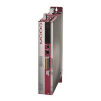
Moog MSD Operation Manual (90 pages)
AC-AC Servo Drive
Brand:
Moog
| Category:
Servo Drives
| Size: 8 MB
Table of Contents
Table of Contents
3
1 General
7
Target Group
7
Prerequisites
7
Reference Documents
7
Order Code
8
Data on Manufacture
9
Scope of Supply
9
Pictograms
9
Disclaimer
9
Disposal
9
Helpline/ Support & Service
10
2 Safety
11
Overview
11
Measures for Your Safety
11
General Safety Instructions and Warnings
12
Intended Use
12
Repair
13
Misuse
13
Responsibility
13
Relevant Laws, Standards and Directives Applied
13
Declaration of Conformity
14
MSD Servo Drive AC-AC Size 1 to Size 7
14
3 Mechanical Installation
15
Mechanical Installation
15
Notes for Installation
15
Mounting (Air and Liquid Cooling)
15
Dimensions, Devices with Air Cooling
16
Mounting Clearances
16
Dimensions, Devices with Liquid Cooling
18
Mounting Clearances
18
Cooling Circuit Connection
20
4 Electrical Installation
21
Notes for Installation
21
Effective EMC Installation
21
Cable Type
21
Routing of Cables
21
Usage with Mains Choke
22
Usage with Internal Mains Filters
22
Usage with External Mains Filters
22
Earthing Measures
22
Shielding Measures
23
External Components
23
Overview of the Connections, Size 1 to Size 4
24
Connection Diagram
25
Overview of the Connections, Size 5 to Size 6A
26
Connection Diagram
27
Overview of the Connections, Size 7
28
Connection Diagram
29
Connection of PE Conductor
30
Electrical Isolation Concept
30
Connection of the Supply Voltages
32
Connection of the Control Section Supply (+24 V DC)
32
Connection of Power Section Supply (400/460/480 V AC)
33
AC Mains Supply, Size 1 to Size 4
34
AC Mains Supply, Size 5 to Size 6A
35
AC Mains Supply, Size 7
35
Connection Diagram, Precharging (Only Size 7)
36
Control Connections
37
Specification of the Control Connections
37
Brake Driver
38
Specification, USB Interface
39
Specification, Ethernet Interface
39
Option 1 (Communication)
39
Option 2 (Technology)
40
Encoder Connection
40
Encoder Connection for Servo Motors
40
Allocation of Motor/Encoder Cable to the Servo Drive
40
Ready Made Encoder Cables
41
Resolver Connection
41
Connection for High-Resolution Encoders
42
Motor Connection
43
Motor Connection for Servo Motors
43
Ready Made Motor Cable
44
Switching in the Motor Cable
45
Braking Resistor (RB)
45
Protection in Case of Brake Chopper Fault
45
Model with Integrated Braking Resistor Size 1 to Size 4
46
Model with Integrated Braking Resistor Size 5 to Size 7
46
Method to Calculate the Continuous Braking Power
47
Connection of an External Braking Resistor
47
5 Commissioning
49
Notes for Operation
49
Initial Commissioning
49
Switching on Control Supply
50
Establish Connection between PC and Servo Drive
50
Configuring Parameters
50
Controlling Drive Using Moog D Rive a Dministrator 5
50
Serial Commissioning
52
Integrated Control Unit
52
Function of Buttons T1 and T2
53
Display
54
Parameter Menu (PA)
54
Ethernet IP Address Menu (IP)
55
Field Bus Address Menu (Fb)
56
6 Diagnostics
57
Status Indication on the Device
57
Device States
57
Error Indication
57
Status and Error Indication in MDA5
58
Safe Torque off (STO)
61
A Appendix
63
Current Carrying Capacity of the Servo Drives
63
G392-004A (Air Cooling, 1 X 230 V AC)
63
Current Carrying Capacity Size 1 to Size 4, Air Cooling, Three-Phase
64
Current Carrying Capacity, Size 5 to Size 6A, Air Cooling
66
Current Carrying Capacity Size 3 to Size 4, Liquid Cooling
68
Current Carrying Capacity Size 5 to Size 6A, Liquid Cooling
69
Current Carrying Capacity Size 7, Liquid Cooling
71
Technical Data, MSD Servo Drive
72
G392-004A to G392-016, Air Cooling
72
G392-020 to G392-072, Air Cooling
73
G392-090 to G392-170, Air Cooling
74
G395-016 to G395-070, Liquid Cooling
75
G395-084 to G395-210, Liquid Cooling
76
G395-250 to G395-450, Liquid Cooling
77
Power Connections
78
Current Required for the Control Supply
78
Ambient Conditions
78
A.3 Power Connections
78
Permissible Motor Cable Lengths
80
Hydrological Data for the Liquid Cooling
81
Monitoring of the Heat Sink Temperature
81
UL Certification
81
Glossary
83
Advertisement
Moog MSD User Manual (70 pages)
Brand:
Moog
| Category:
Servo Drives
| Size: 1 MB
Table of Contents
Table of Contents
5
1 Safety
7
Measures for Your Safety
7
Read the Operation Manual First
7
Introduction to the SERCOS Interface
7
Operation Modes
7
Key Features
8
Weighting
8
Terms
9
Drive-Controlled Homing
9
2 Commissioning of the SERCOS Interface
11
Connections and Controls - Hardware Variant 1
11
Connections and Controls - Hardware Variant 2
11
Connection of Fibre-Optic Cables
12
Hardware Settings
12
Setting the Transmission Power of the SERCOS Interface
12
Setting the Drive Address Via Parameter
12
Transfer Rate of SERCOS Interface
12
Diagnostic Leds
13
Use of the Distortion LED
13
Checking Fibre-Optic Cables
13
3 SERCOS Communication Phases
15
Communication Phase 0
15
Communication Phase 1
15
Communication Phase 2
15
Communication Phase 3
16
Communication Phase 4
16
4 Parameter Interface
17
Profile Parameters (S-0-XXXX)
17
Manufacturer Specific Parameters (P-0-XXXX)
17
Cyclic Data Transfer
17
Master Control Word
18
Description of Bits 13-15
19
Drive Status Word
20
Drive State Machine
22
Real-Time Control Bits and Real-Time Status Bits
23
Signal Control and Status Words
24
Signal Control Word (S-0-0145)
24
5 Fault, Warning and Status Messages
27
Fault Messages
27
Warning Messages
28
Status Messages
28
Interface Faults and Diagnostic Options
29
Diagnosis of Interface Status
29
Fault Counter for Telegram Failures
29
6 Operation Modes
31
Torque Control
33
Flux Control
34
Position Control with Drive-Controlled Position Profile Generation
35
Position Control Without Tracking Error
37
In-Drive Generation of Pre-Control Signals
37
External Generation of Pre-Control Signals
38
7 Weighting
39
Weighting of Position Data
39
Weighting of Translatory Position Data
39
Weighting of Rotary Position Data
39
Modulo Weighting
41
Position Polarity
41
Weighting of Velocity Data
42
Weighting of Translatory Velocity Data
42
Weighting of Rotary Velocity Data
42
Velocity Polarity
43
Weighting of Acceleration Data
44
Weighting of Translatory Acceleration Data
44
Weighting of Rotary Acceleration Data
44
Weighting of Torque and Force Data
45
Percentage Weighting of Torque and Force Data
45
Weighting of Force Data
45
Weighting of Torque Data
46
Torque Polarity
46
8 Homing
49
Drive-Controlled Homing" Command
49
Setting of SERCOS Encoders 1 / 2
49
Homing Velocity
49
Homing Acceleration
49
Homing Method
49
Reference Distance 1/2
49
Reference Distance Offset 1/2
49
Reference Cam, Limit Switches
50
Function Selector - Digital Inputs and Outputs
50
9 Touchprobe Function
51
10 Parameter Access Via the Service Channel
55
10.1 SERCOS Parameter List
55
Moog MSD User Manual (66 pages)
Brand:
Moog
| Category:
Servo Drives
| Size: 1 MB
Table of Contents
Table of Contents
3
This Manual Applies to the MSD Servo Drive Servo Drive System with the SERCOS III Op Tion Board. 3
3
Safety
7
Measures for Your Safety
7
Read the Operation Manual First
7
Introduction to the SERCOS III Interface
7
Key Features
8
Abbreviations
9
Assembly and Connection
11
Installation and Wiring
11
Pin Assignment of the RJ-45 Socket
11
Meanings of Leds
12
Indication of Operating States on 7-Segment Display
12
Hardware Enable
13
Commissioning and Configuration
15
Commissioning
15
Commissioning Sequence
15
Setting the Slave Bus Address
16
Parameter Setting
17
Format of SERCOS III Parameters
17
Standard Parameters (S-0-XXXX.X.X)
17
Manufacturer-Specific Parameters P-0-XXXX
17
Operation Modes
17
Real-Time Bits
19
Data Transfer
21
Communication Phases
21
Cyclic Data Transfer
21
Mapping of Configurable Real-Time Data
21
Drive Control Word S-0-0134.0.0
21
Description of Bits 13-15
22
Drive Status Word S-0-0135.0.0
23
Non-Configurable Real-Time Data
24
Data Transfer Via the Service Channel (SVC)
24
IP Channel
25
Parameter Setting
25
SERCOS III IP Address
25
Scaling and Weighting
27
Weighting of Position Data
27
Weighting of Translatory Position Data
27
Weighting of Rotary Position Data
27
Modulo Weighting
29
Position Polarity
29
Weighting of Velocity Data
30
Weighting of Translatory Velocity Data
30
Weighting of Rotary Velocity Data
30
Speed Polarity
31
Weighting of Acceleration Data
32
Weighting of Translatory Acceleration Data
32
Weighting of Rotary Acceleration Data
32
Weighting of Torque and Force Data
33
Percentage Weighting of Torque and Force Data
33
Weighting of Force Data
33
Weighting of Torque Data
34
Torque Polarity
34
Scaling Using the Scaling Wizard
35
Scaling of Position Data
35
Scaling of Velocity Data
36
Scaling of Torque Data
36
Scaling of Acceleration Data
37
Functionality
39
MSD Servo Drive User Manual SERCOS
39
Homing
39
Drive-Controlled Homing" Command
39
Setting of SERCOS Encoders 1 / 2
39
Homing Velocity
39
Homing Acceleration
39
Homing Method
39
Reference Distance 1/2
39
Reference Distance Offset 1/2
39
Function Selector - Digital Inputs and Outputs
40
Touchprobe Function
40
Error Messages and Diagnosis
45
Standard Parameters for Error Diagnosis
45
Error Messages in State Class 1 (C1D)
45
Warning Messages in State Class 2 (C2D)
45
Interface Diagnosis
46
Telegram Failure and Error Counter
46
Diagnosis Using the Internal Oscilloscope
47
Standard Parameters
47
Additional Scope Parameters
48
Internal Error List
49
Bibliography
51
Appendix, Glossary
53
Appendix A: Parameter List
53
SERCOS III Standard Parameters
53
Manufacturer-Specific Parameters
57
Advertisement
Moog MSD User Manual (58 pages)
Single-Axis System / Multi-Axis System / Compact
Brand:
Moog
| Category:
Servo Drives
| Size: 2 MB
Table of Contents
Table of Contents
3
How to Use this Manual
5
1 General
7
Measures for Your Safety
7
Introduction to Profibus
7
System Requirements
7
Further Documentation
8
2 Commissioning the Profibus Interface
9
Connections and User Controls
9
Plug Configuration for the Profibus Cable
9
Bus Termination
10
Setting the Drive Address
10
Operating Displays
11
GSD File
11
3 Cyclic Data Transmission - DPV0
13
Parameter Process Data Objects (PPO)
13
Standard "Profidrive" Telegrams
13
User-Specific Ppos
15
PKW Parameter Channel
19
Master Control Word
20
Jog Mode Speed Mode
21
Jog Mode Positioning Mode
22
Jog Mode Reference Value Parameter
22
Drive Status Word
22
Drive Status Machine
24
4 Acyclic Data Transmission - DPV1
27
Examples of Request and Reply Telegrams
32
5 Operating Modes
35
Speed Control
35
Speed Control Circuit and Associated Control Parameters
36
Position Control
37
Position Control Circuit and Associated Control Parameters
39
6 Homing
41
Homing Runs Performed by the Drive
41
Homing Run Speed
41
Homing Run Acceleration
41
Zeroing Offset
41
Homing Cams, Limit Switches
41
Homing Run Methods
43
7 Examples of Commissioning Using Manufacturer-Specific Telegrams
45
Position Control Using PPO 5
45
Conversion of Reference Values and Actual Values Using Factor Group Parameters
46
Examples for Setting the User Factor Group
48
Speed Control Using PPO 2
48
Speed Input
49
Mappable Parameters
50
8 Profibus Parameters
51
9 Appendix Glossary
53
Moog MSD Specification (47 pages)
Brand:
Moog
| Category:
Servo Drives
| Size: 2 MB
Table of Contents
Legal Information
2
Table of Contents
3
General Information
4
Target Group
4
Requirements
4
Applicable Documentation
5
Pictograms
5
Exclusion of Liability
5
Support
6
The Twinsync Technology Option
8
Hardware Requirements
9
Installation
10
Twinsync Connecting Cable Pin Assignment
10
Twinsync Connecting Cable Technical Data
11
Description of Parameters
12
General Parameters of the Twinsync Communication Interface
12
Master/Slave Selector (P 2614) Topt_Twin_Mode
14
Timeout Monitoring for the Communication
14
Structure of a Twinsync Data Telegram
14
Configuration of the Process Data in the Standard-Mapping Mode
15
Configuration of the Process Data in the Extended-Mapping Mode
16
Scaling of the Process Data
16
Parametrization of the Twinsync Master Axis
18
Parametrization of the Twinsync Slave Axis
18
Control Via Twinsync
20
Twinsync Operation Modes
22
Virtual Encoder
22
Selection Via Parameter (P2580) Mpro_Twin_Setting
22
User-Specific Mapping
23
Twin Drive Profile "TWD" (Speed)
24
Speed and Position Control
28
Double Inverter "DI
31
Rack-And-Pinion Drive Control "RPDC
32
Virtual Encoder "VE" (Torque)
34
Dspace Twinsync (Rapid-Prototyping Systems from the Fa. Dspace Company)
35
Interpolating Positioning "IP
36
MSD PLC Control "PLC
36
Position Setpoint (Position Reference Value)
36
Serial Double Inverter "SDI" / Parallel Double Inverter "PDI
37
Gantry Application
39
Extended Mapping Mode
40
Dual Stator Winding Motor "DSW
42
Monitoring Functions / Error Messages
44
Index
45
Advertisement
Related Products
MOOG MSD C2
MOOG MSD C3
MOOG MSD C5
MOOG MSD C4
Moog MSD G393-004
Moog MSD G393-006
Moog MSD G393-008
Moog MSD G393-012
Moog MSD G393-016
Moog MSD G393-020
Moog Categories
Synthesizer
Control Unit
Servo Drives
Medical Equipment
Security Camera
More Moog Manuals
Login
Sign In
OR
Sign in with Facebook
Sign in with Google
Upload manual
Upload from disk
Upload from URL