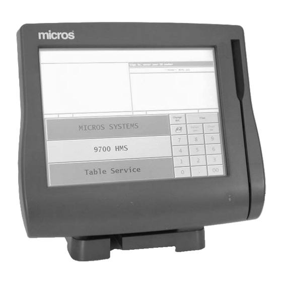
Micros Systems Workstation 4 Manuals
Manuals and User Guides for Micros Systems Workstation 4. We have 2 Micros Systems Workstation 4 manuals available for free PDF download: Service Manual, Setup Manual
Micros Systems Workstation 4 Service Manual (226 pages)
Brand: Micros Systems
|
Category: Touch terminals
|
Size: 9 MB
Table of Contents
-
Preface
10 -
-
Chapter 1
14-
Introduction14
-
-
Chapter 2
40-
-
Core Logic45
-
Eeprom72
-
-
RS422 Port a73
-
RS422 Port B74
-
-
Chapter 3
88-
Introduction88
-
POST Errors97
-
-
Chapter 4
124-
USB Interface137
-
Companion Device138
-
USB Hub138
-
-
-
EEPROM Interface147
-
Chapter 5
152-
Introduction152
-
-
Chapter 6
184-
Introduction184
-
-
-
Appendix A
216-
In this Appendix216
-
-
RS232 Connector218
-
Hook-Up Cables224
-
Advertisement

Micros Systems Workstation 4 Setup Manual (128 pages)
Brand: Micros Systems
|
Category: Touch terminals
|
Size: 4 MB
Table of Contents
-
Preface
8 -
-
The System12
-
Reset Switch13
-
Approvals32
-
-
-
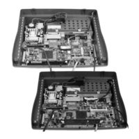
System Board39
-
-
-
Cabinet62
-
The IO Panel63
-
Installation65
-
Operation68
-
-
LCD Pole Display108
-
Cash Drawer109
-
VFD Pole Display111
-
-
-
Idn114
-
Lcc115
-
Rs232115
-
RS232 Connector116
-
USB Connectors117
-
-
Hook-Up Cables120
-
Advertisement