
Related Manuals for Micros Systems Workstation 4 LX


Summary of Contents for Micros Systems Workstation 4 LX
- Page 1 ® Systems, Inc. Workstation 4 Workstation 4 LX Field Service Guide Copyright 2004 - 2008 By MICROS Systems, Inc. Columbia, Maryland USA All Rights Reserved Part Number 100016-118 (4th Edition)
- Page 2 Warranties Although the best efforts are made to ensure that the information contained in this manual is complete and correct, MICROS Systems, Inc. makes no warranty of any kind with regard to this material, including but not limited to the implied warranties of marketability and fitness for a particular purpose.
-
Page 3: Table Of Contents
WS4 System Boards - A Short History ......1-5 The Workstation 4 LX System Board ......1-7 Workstation 4 System Board and Components. - Page 4 Table of Contents Workstation 4 Technical Overview Workstation 4 System Block Diagrams ......2-2 SC3200 GX1 Processor, Video Processor, Core Logic and Super IO .
- Page 5 Table Of Contents Interface Board Description ....... . . 2-46 Cables .
- Page 6 Workstation 4 LX Technical Overview Workstation 4 LX System Board Block Diagram ....4-2 LX800 Processor and TFT Controller ......4-3 Processor Core .
- Page 7 Operational Troubleshooting ........5-4 Workstation 4 LX Boot Sequence ......5-4 Pre-boot Firmware Applications - Background .
- Page 8 Remove and Replace the Workstation 4 System Board ....6-11 Remove and Replace the Workstation 4 LX System Board ... . 6-15 Remove and Replace the LCD panel .
- Page 9 Preface In this preface, you’ll find information about this manual. Refer to the preface if you have questions about the organization, conventions, or contents of this manual. In this section Why Read This Manual?................ix How This Manual Is Organized ...............xi Notation Conventions................xii Workstation 4 and 4 LX Field Service Guide...
-
Page 10: Preface
AMD Geode SC3200 Processor Specification Update DiskOnChip Millennium Plus Data Sheet Rev. 1.7 National Semiconductor Corporation PC87360 Super IO Datasheet National Semiconductor Corporation DP83815 Ethernet Controller Datasheet Workstation 4 LX: ™ AMD Geode LX Processor Databook - October 2005 ™... - Page 11 Preface How This Manual is Organized How This Manual is Organized The fourth edition of this field service guide incorporates the Workstation 4 LX System Board Field Replacement Units (FRUs), technical descriptions, and test procedures. Chapter 1 combines the Workstation 4 and Workstation 4 LX spare Field Replacement Units (FRUs).
-
Page 12: Symbols
Preface Notation Conventions Notation Conventions Symbols NOTE This symbol brings special attention to a related item. WARNING This symbol indicates that specific handling instructions or procedures are required to prevent damage to the hardware or loss of data. SHOCK HAZARD This symbol calls attention to a potential hazard that requires correct procedures in order to avoid personal injury. -
Page 13: Introduction To The Ws4/Ws4 Lx Frus
Introduction to the WS4/WS4 LX FRUs This section introduces the Workstation 4, Workstation 4 LX, and LCD Customer Display FRUs. With the addition of the Workstation 4 LX, a new section on how to distinguish each system board has been added. In this chapter Introduction....................1-2... -
Page 14: Introduction
172,000 units in the field. PMA 07-892 announces the WS4 end-of-life in July 2007, with hardware support available through 2012. This edition of the Field Service Guide introduces the Workstation 4 LX system board and related FRUs. All other components including casework, LCD, power supply, touchscreen, and mag stripe reader are common to both workstations. -
Page 15: Base Casework - Ws4 And Ws4Lx
Introduction to the WS4/WS4 LX FRUs Base Casework - WS4 and WS4LX Base Casework - WS4 and WS4LX Figure 1-1 shows the spare parts related to the WS4 or WS4 LX workstation base. Includes plastic, sheet metal, hardware and miscellaneous components. Figure 1-1: WS4/WS4LX Base Casework Related Spare Parts Workstation 4 and 4 LX Field Service Guide... - Page 16 Introduction to the WS4/WS4 LX FRUs Base Casework - WS4 and WS4LX • Clamp, Cable Hold Down - P/N 600030-006. Kit of four pieces. Mounted on the RF Shield Cover, one pair is used for the display cable and toroid and the second pair is used for the magnetic stripe reader interface cable and toroid.
-
Page 17: System Boards And Components
Introduction to the WS4/WS4 LX FRUs System Boards and Components System Boards and Components This section starts with a discussion of each system board revision from the first generation, through the first ‘ROHS’ compliant revision, then on to latest system board, the WS4 LX. - Page 18 ROHS packaging offered improved heat dissipation and heat sink was not required. Production of the ABRD36 board ends with the introduction of the Workstation 4 LX System Board. Workstation 4 and 4 LX Field Service Guide...
-
Page 19: The Workstation 4 Lx System Board
System Boards and Components The Workstation 4 LX System Board The Workstation 4 LX System Board is also ROHS compliant and uses the designation ABRD86-n, where ‘n’ represents the hardware revision. More than just a board ‘spin’, the LX is a new hardware architecture - requiring a new API, and platform files. -
Page 20: Workstation 4 System Board And Components
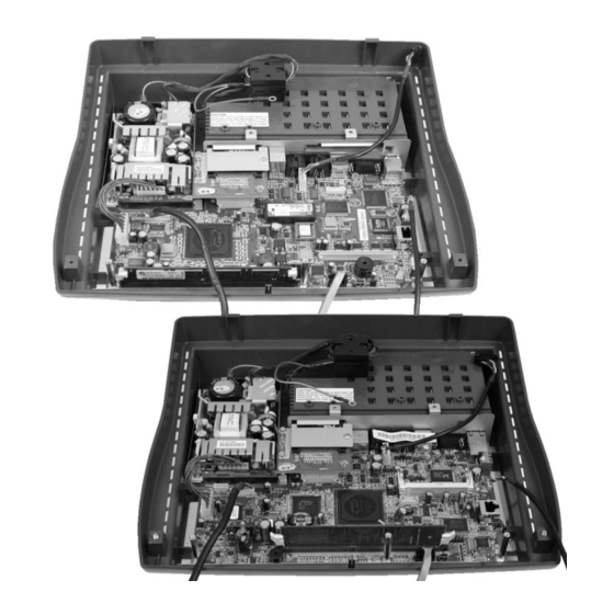
Introduction to the WS4/WS4 LX FRUs Workstation 4 System Board and Components Workstation 4 System Board and Components Figure 1-5 shows the original WS4 with the AB28 series or ABRD36 system board and components. Figure 1-5: Original Workstation 4 System Board and Components •... - Page 21 Power Supply - P/N 700351-019. 65W open frame power supply with +5V, +12V and -12V outputs. This power supply is compatible with Workstation 4 and Workstation 4 LX units. • Power Supply Fuse, Kit of 10 pcs. - P/N 000160-001.
-
Page 22: Workstation 4 Lx System Board And Components
Introduction to the WS4/WS4 LX FRUs Workstation 4 LX System Board and Components Workstation 4 LX System Board and Components Figure 1-6 shows the WS4 LX System Board ABRD86 and components. Figure 1-6: WS4 LX System Board and Components •... - Page 23 • Cable, Rear LCD Customer, Integrated - P/N 400446-007. This cable is pre-installed on all Workstation 4 LX System Boards. It attaches between J1 on the System Board to the optional Integrated LCD Customer Display. Compatible with the WS4 and KWS4.
-
Page 24: Cables And Toroids
Introduction to the WS4/WS4 LX FRUs Cables and Toroids Cables and Toroids This section presents the cables available for the WS4 and adds the WS4 LX. Considering the original AB28 series system board connector changes, three LCD panels and the recent introduction of the WS4 LX System board, a total of four LCD interface cables and two backlight interface cables are available. -
Page 25: Cable, Sharp Lcd Display, Rev F/G
Introduction to the WS4/WS4 LX FRUs Cables and Toroids Cable, Samsung LCD Display, WS4 REV I, WS4 ROHS - P/N 300331-201 The cable shown in Figure 1-8 connects between the EOL Samsung LCD LVDS Board and System Board AB28-I. This cable is not compatible with a Sharp LCD and system boards AB28-F and AB28-G. -
Page 26: Cable Inverter, F/G Bd, Ws4
Introduction to the WS4/WS4 LX FRUs Cables and Toroids Cable, Sharp LCD Display, WS4 Rev I, ROHS, or WS4 LX - P/N 300331-203 The cable shown in Figure 1-10 connects a Sharp LCD to WS4 System Board AB28-I, ABRD36, and ABRD86. Not compatible with Samsung LCDs and the AB28-F/G System Boards. -
Page 27: Cable, Inverter To Rev I Bd, Ws4 Or Ws4 Lx
Introduction to the WS4/WS4 LX FRUs Cables and Toroids Cable, Inverter to REV I BD, WS4 or WS4 LX - P/N 300331-200 The cable shown in Figure 1-12 connects between the backlight inverter board and system boards AB28-I, ABRD36, and ABRD86. This cable is not compatible with WS4 System Boards AB28-F and AB28-G. -
Page 28: Cable Kit, Power In - Power Out, Ac Conn
Introduction to the WS4/WS4 LX FRUs Cables and Toroids Cable Kit, Power In - Power Out, AC Conn - P/N 000170-003 Figure 1-14 displays the Power In and Power Out Cable Kit. It consists of the AC input cable assembly and the power supply to system board cable. The Power-In cable does not include a toroid. -
Page 29: Ac Power Input Cable
Introduction to the WS4/WS4 LX FRUs Cables and Toroids AC Power Input Cable - P/N 200153-001 Replacement AC Power Cable for Workstation 4 and Workstation 4 LX. Figure 1-16: Replacement AC Power Cable Workstation 4 and 4 LX Field Service Guide... -
Page 30: Workstation 4 And 4 Lx - Lcd/Touchscreen/Mag Stripe Reader
Introduction to the WS4/WS4 LX FRUs Workstation 4 and 4 LX - LCD/Touchscreen/Mag Stripe Reader Workstation 4 and 4 LX - LCD/Touchscreen/Mag Stripe Reader This section lists all components in the WS4 or WS4 LX top cover, including the LCD, touchscreen, and mag stripe reader. Samsung LCD Related The Samsung LTM121SI-T01 LCD panel is no longer available, EOL in late 2004. - Page 31 Introduction to the WS4/WS4 LX FRUs Workstation 4 and 4 LX - LCD/Touchscreen/Mag Stripe Reader • Backlight Inverter Board - P/N 700633-005. This board attaches to the LCD bracket and powers the Samsung or Sharp LCD backlight tubes. Two versions of the backlight inverter board now exist. The original board can be identified by the number ‘XB33’...
-
Page 32: Sharp Lcd Related
Introduction to the WS4/WS4 LX FRUs Workstation 4 and 4 LX - LCD/Touchscreen/Mag Stripe Reader Sharp LCD Related Figure 1-18 shows the spare parts available for the Sharp LCD. These items are compatible with both the WS4 and WS4 LX. Figure 1-18: Sharp LCD Related FRUs - WS4 and WS4 LX •... -
Page 33: Touchscreen And Front Cover Plastic
Introduction to the WS4/WS4 LX FRUs Workstation 4 and 4 LX - LCD/Touchscreen/Mag Stripe Reader Touchscreen and Front Cover Plastic Figure 1-19, shows the part numbers for the touch screen glass, gasket, and the top cover plastic. These items are compatible with the WS4 and WS4 LX. Figure 1-19: WS4 and WS4 LX Touchscreen and Top Cover •... -
Page 34: Top Cover - Mag Stripe Reader Assembly And Cover
Introduction to the WS4/WS4 LX FRUs Workstation 4 and 4 LX - LCD/Touchscreen/Mag Stripe Reader Top Cover - Mag Stripe Reader Assembly and Cover - WS4 and WS4 LX Figure 1-20 shows the MSR and related components installed in the top cover. Figure 1-20: Magnetic Stripe Reader FRUs - WS4 and WS4 LX •... -
Page 35: Lcd Customer Display
Introduction to the WS4/WS4 LX FRUs LCD Customer Display LCD Customer Display This section lists the available FRU’s for the LCD Customer Display. See Chapter 6 for instructions on removing and replacing these items. The WS4, KWS4, WS4 LX and WS5 support this display. LCD Interface Board - P/N 400702-001 The LCD Customer Display Interface Board is used for the Integrated, Pole and Adjustable Stand Pole mounted display. -
Page 36: Cable, Lcd Pole And Rear Display Head
Introduction to the WS4/WS4 LX FRUs LCD Customer Display Cable, LCD Pole and Rear Display Head - P/N 300331-251 This replacement cable connects between the LCD Interface Board in the rear or pole LCD display housing to cable 400446-007 (Integrated/Rear) or 300331-250 (Pole). Figure 1-23: Replacement LCD Customer Display Cable Cable Extension, LCD Pole Display - P/N 300331-250 This cable is installed in the pole and connects between 300331-251 (above) and the... -
Page 37: Kit, Front/Rear Cover, /W Lens, Screws, Pole Mount Hinge
Introduction to the WS4/WS4 LX FRUs LCD Customer Display Kit, Front/Rear Cover, /w Lens, Screws, Pole Mount Hinge - P/N 000160-010 LCD Customer Display housing kit with Front and Rear Plastic covers, pole mount and pre-installed 2nd generation hinge assembly. Figure 1-25: Pole Display Plastic Replacement Kit Kit, Front/Rear Cover, /w Lens, Screws, Rear Mount Hinge - P/N 000160-011 LCD Customer Display housing kit with Front and Rear Plastic covers, integrated... - Page 38 Introduction to the WS4/WS4 LX FRUs LCD Customer Display 1-26 Workstation 4 and 4 LX Field Service Guide...
- Page 39 WS4 Technical Overview This Chapter contains the Workstation 4 System Board AB28 and ABRD36 technical descriptions. Refer to Chapter 4 for more information about the Workstation 4 LX System Board, ABRD86. In this chapter Workstation 4 System Block Diagrams ............2-2 SC3200 GX1 Processor, Video Processor, Core Logic and Super IO ..
-
Page 40: Workstation 4 System Block Diagrams
WS4 Technical Overview Workstation 4 System Block Diagrams Workstation 4 System Block Diagrams In the following pages, the three major configurations of the original Workstation 4 are presented. Each highlights the system board and LCD configuration as it changes over time. Figure 2-1 shows the initial configuration of the WS4 with System Board AB28-F/G and a Samsung LCD panel. - Page 41 WS4 Technical Overview Workstation 4 System Block Diagrams Figure 2-2 shows a block diagram of the WS4 based on the AB28-I System Board and the Sharp ‘LG41’ LCD. Figure 2-2: WS4 Block Diagram /w AB28-I System Board and Sharp LCD Panel The AB28-I System Board introduces the COM3 Multiplexer in order to fully support the MICROS LCD Customer Display, introduced in late 2004.
- Page 42 GR2.2 Platform software to function correctly. The configuration shown above entered production in approximately June 2006 and continued until the release of the Workstation 4 LX in July 2007. Non-ROHS compliant Workstation 4s were also produced during this period.
-
Page 43: Sc3200 Gx1 Processor, Video Processor, Core Logic And Super Io
WS4 Technical Overview SC3200 GX1 Processor, Video Processor, Core Logic and Super IO SC3200 GX1 Processor, Video Processor, Core Logic and Super IO REF: AB28/ABRD36 - Sheets 1, 2 and 3 The SC3200 was originally a member of National Semiconductor Corp. ‘WebPad On A Chip’... -
Page 44: Gx1 Processor
WS4 Technical Overview SC3200 GX1 Processor, Video Processor, Core Logic and Super IO GX1 Processor The Geode GX1 combines advanced CPU performance with MMX™ support, accelerated 2D graphics, a 64-bit synchronous DRAM (SDRAM) interface controller, PCI Bus Controller, and a display controller. ™... -
Page 45: Core Logic
WS4 Technical Overview SC3200 GX1 Processor, Video Processor, Core Logic and Super IO Core Logic The Core Logic of the SC3200 device includes the following PC AT functionality: a USB interface, IDE interface, PCI Bus Interface, LPC (Low Pin Count) interface, ACPI 1.0 compliant power management, Video Input Port (VIP), and support for an audio codec. -
Page 46: Pci And Sub-Isa Bus Interface
WS4 Technical Overview PCI and Sub-ISA Bus Interface PCI and Sub-ISA Bus Interface REF: AB28/ABRD36 - (Sheets 2, 5, 6 and 10) Figure 2-5 shows a block diagram of the SC3200 PCI and Sub-ISA Bus as implemented on the original Workstation 4 System Boards. Figure 2-5: SC3200 PCI/Sub-ISA Bus Interface In order to reduce the number of pins on the SC3200 device, the PCI and Sub-ISA bus pins are shared. -
Page 47: Sub-Isa Bus Interface
WS4 Technical Overview PCI and Sub-ISA Bus Interface As shown in Figure 2-5, two devices are located on the PCI Bus. U12 is a National Semiconductor Corp DP83815 10/100 Ethernet Controller, and the optional PCMCIA Daughter Card XB37 or XBRB37 includes a RL5C475II PCI to Card Bus Controller. - Page 48 WS4 Technical Overview PCI and Sub-ISA Bus Interface IDE Interface (AB28/ABRD36 - Sheets 1 and 13) The core logic module integrates a PCI bus mastering ATA-4 compatible IDE Controller. This controller supports Ultra DMA, Multi-word DMA and Programmable I/O (PIO) modes. Two IDE devices are supported by the SC3200. However, on the WS4 system board only a single Compact Flash card is attached to this interface.
-
Page 49: Sc3200 Super I/O
WS4 Technical Overview SC3200 Super I/O SC3200 Super I/O REF: AB28/ABRD36 - Sheets 1 and 2 The SC3200 Super IO module comprises a collection of 8 functional blocks, host interface, and a central configuration register set, all attached to the internal 8-bit data bus. -
Page 50: Pc87360 Super Io
WS4 Technical Overview PC87360 Super IO PC87360 Super IO REF: AB28 /ABRD36 - Sheet 19 In addition to the Super IO module within the SC3200, the system board also incorporates U15, a National Semiconductor Corp PC87360 Super IO chip to cover additional IO requirements. -
Page 51: General Purpose Io
WS4 Technical Overview PC87360 Super IO General Purpose IO (AB28-I, ABRD36) The PC87360 includes up to 37 general purpose IO (GPIO) pins arranged as four 8-bit ports (ports 0, 1, 2, and 4) and one 5-bit port (port 3). All pins in port 0 are I/O capable of full event detection capability, enabling them to trigger the assertion of IRQ, SMI (System Management Interrupt), and (Power Up Request) signals. -
Page 52: Operator Led Control
WS4 Technical Overview PC87360 Super IO Operator LED Control (REF: AB28 /ABRD36 - Sheet 19) The Operator LED is mounted directly to the system board in the lower right-hand corner. A light pipe attached to the top cover is positioned over the LED when the cover is in place. -
Page 53: Serial Interface
WS4 Technical Overview PC87360 Super IO Serial Interface The PC87360 Device contains two serial ports, labeled UART1 and UART2 with IR support. Each UART contains the equivalent of a 16550 UART with 16 byte FIFO buffer. UART1 UART1 is assigned to RS422 Port A. RS422 Port A is one of two multi-protocol serial ports on the WS4. -
Page 54: Access.bus Interface
WS4 Technical Overview PC87360 Super IO ACCESS.bus Interface (AB28 /ABRD36 Sheet 19) The ACB is a two-wire synchronous serial interface compatible with the ACESS.bus physical layer. It is compatible with the Intel SMBus (System Management Bus) and Phillips I C bus architectures. The ACB can be configured as a bus master or slave, and can maintain bi-directional communication with both master and slave devices. -
Page 55: Tft Lcd Interface
WS4 Technical Overview TFT LCD Interface TFT LCD Interface REF: AB28/ABRD36 - Sheets 1 and 8 Figure 2-11 displays a block diagram of the video processor and how it is interconnected with other modules in the SC3200. It is a low power, high-performance, TFT display interface. - Page 56 WS4 Technical Overview TFT LCD Interface Name Type Description TFTDE Data Enable signals for Red, Blue, and Green pixel data. FP_VDD_ON Enables power to the LCD panel with the proper timing sequence. The video output signals are fed to U1, a TI 75LVDS84A FlatLink Transmitter. This device converts the 21-bits of TTL/CMOS timing and pixel data from the SC3200 into three data and a single clock streams.
- Page 57 WS4 Technical Overview TFT LCD Interface Figure 2-13: WS4 LCD Interface - Sharp LCD Panel Workstation 4 and 4 LX Field Service Guide 2-19...
-
Page 58: Touchscreen Interface
WS4 Technical Overview Touchscreen Interface Touchscreen Interface REF: AB28/ABRD36 - Sheet 7 The touchscreen interface supports a 5-wire resistive touchscreen and is located on Sheet 7 of the Schematic. The touchscreen controller output is connected to COM2. UART1 in the SC3200 is dedicated to this interface. The interface consists of touchscreen controller U38, microcontroller U37 and serial EEPROM U40. -
Page 59: Optional Pcmcia Daughter Card
WS4 Technical Overview Optional PCMCIA Daughter Card Optional PCMCIA Daughter Card REF: XB37/XBRB37 - Sheet 1 The optional PCMCIA Daughter Card can be used on the AB28 and ABRD36 System Boards. It connects directly to the PCI bus at system board connector J18 and is used to support a PCMCIA wireless card. -
Page 60: Optional Mini-Pci Daughter Card
WS4 Technical Overview Optional Mini PCI Daughter Card Optional Mini PCI Daughter Card REF: XBRD68 - Sheets 1 and 2 The Mini PCI Daughter Card appeared in 2006, replacing the PCMCIA Daughter Card, above. The card contains no active components, but simply routes the PCI signals up from the AB28 or ABRD36 system board connector to a Type IIIA 124-Pin card edge connector. -
Page 61: Complex Programmable Logic Device (Cpld)
WS4 Technical Overview Complex Programmable Logic Device (CPLD) Complex Programmable Logic Device (CPLD) REF: AB28/ABRD36 - Sheet 17 AB28 series Workstation 4 System Boards use the ispLSI2064E 44-Pin High Density Programmable Logic Device, designated U22. This device contains 1000 gates, 32 8-bit registers, and 32 programmable IO pins. - Page 62 WS4 Technical Overview Complex Programmable Logic Device (CPLD) PWM0-6 ADDR1 ADDR0 STROBE Action Data Low->High Write Backlight Data to Backlight PMW 1011100 Low->High Activate Cash Drawer A Solenoid 1011101 Low->High Activate Cash Drawer B Solenoid 1011000 Low->High Deactivate Cash Drawer A Solenoid 1011001 Low->High...
-
Page 63: Power Button
WS4 Technical Overview Complex Programmable Logic Device (CPLD) Power Button (REF: AB28 Sheets 11, 12, 17, and 19) This section describes how the CLPD and CPU manage the power button as well as controlling the on-board voltage regulators as the WS4 transitions between the power management states. - Page 64 WS4 Technical Overview Complex Programmable Logic Device (CPLD) Power Button (REF: ABRD36 - Sheets 11, 12, 17, and 19) Figure 2-16 shows the ABRD36 implementation of the CPLD circuit. The pin numbers of the CLPD and SC3200 have changed to reflect the new devices, but otherwise the operation of the power button has not changed.
- Page 65 WS4 Technical Overview Complex Programmable Logic Device (CPLD) • If the previous power management state was , the workstation NOPOWER remains in the NOPOWER state and waits for user to press the power button. • If the previous power management state was , the workstation SUSPEND transitions to the...
-
Page 66: Reset Circuit
WS4 Technical Overview Complex Programmable Logic Device (CPLD) NOPOWER When the workstation is in the state and the user presses and holds the power button for more than four seconds, the workstation transitions to the NOPOWER state. Refer to Figure 2-15. When the power button is pressed and held, the CPLD pulses the input to the SC3200 CPU. -
Page 67: Wake On Lan Power Management Event
WS4 Technical Overview Complex Programmable Logic Device (CPLD) signal is produced by U35, an NSC LM2636 programmable regulator PWRGD that powers the SC3200 CPU located on Sheet 12. PWRGD goes true to indicate the regulator output is stable. The second source is U34, a NSC LP3470-2.63 Tiny Power On Reset Circuit located on Sheet 12. -
Page 68: Lcd Backlight Control
WS4 Technical Overview Complex Programmable Logic Device (CPLD) LCD Backlight Control (REF: AB28/ABRD36 - Sheet 17) The CPLD provides LCD Backlight Control as shown in Figure 2-18 below. Figure 2-18: Backlight Brightness Control Pulse Width Modulation (PWM) Brightness Control Table 2-2 summaries the pre-selected PWM values for the standard Dim, Normal, and Bright backlight settings available through the WS4 API. -
Page 69: Cash Drawer Interface
WS4 Technical Overview Complex Programmable Logic Device (CPLD) Cash Drawer Interface (REF: AB28/ABRD36 - Sheets 17 and 18) The system board supports two cash drawers using the large 4-pin DIN connectors. The WS4 API is positioned between the POS application software and the CPLD, writing once to start the drawer open pulse and writing a second time to stop the pulse. -
Page 70: Dp83815 10/100 Mbps Pci Ethernet Controller
WS4 Technical Overview DP83815 10/100 Mbps PCI Ethernet Controller DP83815 10/100 Mbps PCI Ethernet Controller U12, a National Semiconductor Corporation DP83815 Ethernet Controller, consists of a MAC/BIU Media Access Controller/Bus Interface Unit), a physical layer interface, SRAM, and miscellaneous support logic. The MAC/BIU includes the PCI bus, BIOS RAM and EEPROM interfaces, and the 802.3 compatible Transmit and Receive MAC. - Page 71 WS4 Technical Overview DP83815 10/100 Mbps PCI Ethernet Controller It is important to note that while full auto-negotiation with the use of Fast Link Pulse code words can interpret and configure to support full-duplex, parallel detection can not recognize the difference between full and half duplex from a fixed 10 Mb/s or 100 Mb/s partner over twisted-pair.
-
Page 72: Eeprom
WS4 Technical Overview DP83815 10/100 Mbps PCI Ethernet Controller A ‘Magic Packet’ is a special Ethernet frame that contains a unique, specific data sequence in the data portion of the frame. When the WS4 is in SUSPEND power management states, the Wake On LAN pattern matching logic NOPOWER monitors the incoming Ethernet frames addressed to the node and provides a wake event to the system upon receipt of a Magic Packet™. -
Page 73: Rs422 Port A And Rs422 B
WS4 Technical Overview RS422 Port A and RS422 B RS422 Port A and RS422 B The WS4 features a pair of multi-purpose RS422/232 ports utilizing 8-Pin modular connectors called RS422-A and RS422-B. Each port is identical to the Eclipse IDN/LCC port. Pin-outs for the RS422 and RS232 sections of each port can be found in Appendix B. -
Page 74: Rs422 Port B
WS4 Technical Overview RS422 Port A and RS422 B SIgnal Name Type Description RXD4_422 Contains serial data received on the RS422 Interface. Produced by ANDing RXD4_422# with inverted 422_232_SEL_4 at U14-6. RXD4 Contains serial data received from either the RS422 or RS232 interface. Produced by ORing RXD4_232 and RXD4_422 at U11-8. - Page 75 WS4 Technical Overview RS422 Port A and RS422 B SIgnal Name Type Description RXD5_232 Contains serial data received from the RS232 Interface. Produced by ANDed RXD5_232# and inverted 422_232_SEL_5 at U13-3. RXD5_422 Contains serial data received from the RS422 Interface. Produced by ANDing RXD5_422# and inverted 422_232_SEL_5 at U13-8.
-
Page 76: Customer Display/Mag Card Reader Port (Com3)
WS4 Technical Overview Customer Display/Mag Card Reader Port (COM3) Customer Display/Mag Card Reader Port (COM3) REF: AB28 Sheets 18 and 19 UART2 in Super IO U15, is dedicated to COM3. The system board revision determines how this port is configured, as described in the sections below. COM3 Configuration - AB28-F and AB28-G On all WS4 system boards, COM3 is shared between the Mag Stripe Reader and Customer Display interfaces. - Page 77 WS4 Technical Overview Customer Display/Mag Card Reader Port (COM3) The Rear and Pole LCD Customer Display share a common housing with individual mounting hinges for the rear and pole versions. Within the housing is the same LCD Interface Board, interface cable, 240x64 LCD Module, and mounting bracket.
-
Page 78: Com3 Configuration - Ab28-I Or Abrd36-B
WS4 Technical Overview Customer Display/Mag Card Reader Port (COM3) WS4 System Board COM3 Configuration - AB28-I or ABRD36-B To fully support a high-speed LCD Customer Display interface while at the same time, retaining support for slower Mag Stripe Reader and VFD Customer Display sharing the same port, the COM3 interface changes significantly on the AB28-I system board. - Page 79 WS4 Technical Overview Customer Display/Mag Card Reader Port (COM3) Figure 2-24 shows a detailed diagram of the multiplexer, summarized from Sheets 18, 19, and 20 of the AB28-I Schematic. Figure 2-24: AB28-I System Board COM3 Mux Workstation 4 and 4 LX Field Service Guide 2-41...
-
Page 80: Multiplexer Operation
WS4 Technical Overview Customer Display/Mag Card Reader Port (COM3) Multiplexer Operation The primary component is U47, an 74HC125 Quad Buffer with 3-state outputs. The device is composed of four buffers, the output of which is controlled by an associated enable input. A high on the pin causes the associated buffer output to assume the High Impedance or OFF state. - Page 81 WS4 Technical Overview Customer Display/Mag Card Reader Port (COM3) The API switches the interface baud rate from 9600 to 115K baud. The Pole/Rear LCD Customer Display interfaces are enabled by setting POLE_OE# low at U47-4 to pass serial data appearing on at U47-6.
-
Page 82: Optional Lcd Customer Display
WS4 Technical Overview Optional LCD Customer Display Optional LCD Customer Display General Description The Optional Rear and Pole LCD Customer Display is compatible with the WS4, WS4 LX, KWS4 and Workstation 5. In addition to supporting many new graphics features, it emulates the 2x20 IEE VFD Customer Display. The following pages provide a general description of this display. -
Page 83: Interface Board And Lcd
WS4 Technical Overview Optional LCD Customer Display Interface Board and LCD A simple block diagram of the LCD Customer Display is shown in Figure 2-26. Internally, the LCD Customer Display consists of the LCD interface board and Optrex 240x64 STN LCD panel. A pair of 36-conductor ribbon cables carries address, data, and power from the interface board to the LCD. -
Page 84: Interface Board Description
WS4 Technical Overview Optional LCD Customer Display Interface Board Description Figure 2-27 shows a block diagram of the LCD Customer Display interface board. Figure 2-27: LCD Interface Board Block Diagram The LCD interface board is used on the Rear and Pole mount versions of the LCD Customer Display as well as the KWS4 Operator Display. -
Page 85: Cables
Enabling the LCD Customer Display - WS4 LX The Workstation 4 LX API features the ability to automatically detect and use either the IEE 2x20 VFD, or LCD Customer Display. To determine what display is installed, the API takes advantage of the fact that each customer display operates at different baud rates and only the LCD is capable of returning data to the host workstation. - Page 86 WS4 Technical Overview Optional LCD Customer Display 2-48 Workstation 4 and 4 LX Field Service Guide...
- Page 87 Chapter 3 WS4 Troubleshooting This Chapter is your guide to testing and repairing the original Workstation 4 System Boards AB28 and ABRD36. Additional topics include using the built-in DiagUtility and a discussion of the WS4 Platform files. In this chapter Introduction....................3-2 Operational Troubleshooting ...............
-
Page 88: Introduction
WS4 Troubleshooting Introduction Introduction This chapter contains the following sections. • Software Utilities This section describes the diagnostics utilities we have found useful in testing and troubleshooting the Workstation 4. • Diagnostics Overview This section provides tips and procedures specific to troubleshooting the Workstation 4. - Page 89 WS4 Troubleshooting Introduction 4. Touch the ‘DiagUtility’ icon twice to start the WS4 diagnostics utility. 5. The WS4 Diagnostics utility starts and displays the System Info Screen. Using the Soft Keyboard Some of the diagnostics procedures may require a keyboard for alpha or numeric entry.
-
Page 90: Operational Troubleshooting
WS4 Troubleshooting Operational Troubleshooting Operational Troubleshooting This section provides troubleshooting information, voltage test points and POST errors for the original Workstation 4 System Boards, AB28 and ABRD36. Original Workstation 4 Boot Sequence The following procedure describes the boot sequence of the original workstation 4 system board. - Page 91 WS4 Troubleshooting Operational Troubleshooting 4. The blue screen remains visible for about 55 seconds. Note the progress bar under the MICROS logo. A group of Red pixels appears at the left of the progress bar and cycles across to the right side of the bar. Should the workstation fail to start, counting the number of times the Red pixels cycle across the progress bar can help point to a specific problem.
- Page 92 WS4 Troubleshooting Operational Troubleshooting 6. The Workstation 4 boots to the OS desktop. The Client Application Loader should start. The CAL examines the registry to determine if a POS application is installed. If the application is present, CAL checks the server for updates, then starts the application.
- Page 93 WS4 Troubleshooting Operational Troubleshooting Power Button Related Symptoms: When you hold the power button down for four seconds, the workstation enters the state, but when you release the power button, the workstation NOPOWER restarts. • The Workstation is running CPLD Version 9 or previous. The workstation must be returned to MICROS to be upgraded to CPLD Version 10.
-
Page 94: Testing The Power Supply And System Board Voltages
WS4 Troubleshooting Testing the Power Supply and System Board Voltages Testing the Power Supply and System Board Voltages The following procedure describes how to verify that the internal power supply is functional then goes on to check the working output voltages of the original Workstation 4 System Boards, AB28 and ABRD36. - Page 95 WS4 Troubleshooting Testing the Power Supply and System Board Voltages If a single ALWAYS voltage is missing, swap the power supply. If the replacement power supply is missing the same voltage, this is likely a short on the system board causing the power supply output to shut down. On a system board where the ALWAYS voltages are present, but the board is non-responsive, the on-board switched voltage regulators can be checked as detailed in the next step.
- Page 96 WS4 Troubleshooting Testing the Power Supply and System Board Voltages 3. The ABRD36-B System Board adds Q20 and Q21 to control the +5V fed to the Integrated and Pole customer display connectors. All other voltage test points and component designations are the same as the AB28-F, G, and I. Figure 3-3: Checking the ABRD36 System Board Working Voltages The VCC5V_DISP circuit briefly removes power to the integrated and pole customer displays ports when the LCD [Reset] button in the WS4 Diagnostics Utility is pressed.
-
Page 97: Post Errors
WS4 Troubleshooting POST Errors POST Errors POST errors are summarized in the table below. How the WS4 behaves after a POST error is determined by the boot loader version. If boot loader V2.0.08 or earlier encounters a POST error, the error code sounds once, and the unit powers off. - Page 98 WS4 Troubleshooting POST Errors Note 3 The POST cannot detect the Disk On Chip. The device is installed, not installed correctly, not formatted, defective, or a system board/socket problem preventing the POST from accessing the DOC. In addition, there may be instances where a defective or corrupt Disk On Chip prevents the workstation from booting, but a POST error is not reported.
- Page 99 WS4 Troubleshooting POST Errors Note 6 The POST checks SDRAM by reading and writing 0xAA and 0x55 patterns to each memory location. If the DIMM is not installed however, a POST error does not occur. Instead, the workstation exhibits symptoms similar to that of a bad boot loader chip. See Step 2 in the Operational Troubleshooting section.
-
Page 100: Lcd Display Related
WS4 Troubleshooting LCD Display Related LCD Display Related This section lists all LCD display related issues. First, the blank or dark display issues are addressed, the we move on to situations where the display is functional, but experiences visual problems. Let’s define the terms “Dark LCD”... - Page 101 WS4 Troubleshooting LCD Display Related • ROHS Inverter Board XBRB33, GR 2.0 Platform Files and Samsung LCD mis-match. This can occur if the XBRB33 inverter board is installed on a unit with the Samsung LCD and the GR 2.0 platform files. The ROHS compliant version of the Backlight Inverter Board (XBRB33) has the same MICROS P/N as the previous board (XB33), but uses a new transformer with different operating characteristics.
-
Page 102: Touchscreen Related
WS4 Troubleshooting Touchscreen Related Touchscreen Related This section includes several touchscreen related symptoms and applies to the AB28 and ABRD36 system boards. POST Error If a POST error occurs, (short, long beeper with the Operator LED turning solid Red) see the POST error section on page 3-11. Touchscreen Not Responding after Boot-Up Symptoms: The Workstation 4 boots (no POST errors), but the touchscreen does not respond to a touch. - Page 103 WS4 Troubleshooting Touchscreen Related • The touchscreen extension cable is defective. For example, one pin of the original extension cable is pushed out of the connector body and not making contact. On the newer style extension cable, make sure the cable does nor have very sharp bends.
-
Page 104: Local Area Network (Lan) Related
WS4 Troubleshooting Local Area Network (LAN) Related Local Area Network (LAN) Related Workstation 4 Does Not Connect to the LAN Symptoms: The workstation is connected to the server via the LAN, but communications can not be established. The RJ45 LAN connector on the rear panel includes a pair of LEDs to assist with basic LAN troubleshooting., shown in Figure 3-4 below. - Page 105 WS4 Troubleshooting Local Area Network (LAN) Related • Defective or damaged in-wall cabling between the WS4 and other network device. • Defective or non-powered network device. (For example, the WS4 is connected to a network switch, but the device is not powered). •...
- Page 106 WS4 Troubleshooting Local Area Network (LAN) Related • In the IP address tab, make the selection between DHCP or Static IP and enter a static IP address suitable for the site (normally in the 192.168.x.x range) if required. • Restart the WS4 after making changes to network settings. 3-20 Workstation 4 and 4 LX Field Service Guide...
-
Page 107: Mechanical Related
WS4 Troubleshooting Mechanical Related Mechanical Related Power Button Sticks Symptoms: The Power button actuator is recessed and the WS4 does not change states when pressed. • Damaged Power Button Actuator. This can happen on the original WS4 with a S/N of less than 3000. Excessive force on the actuator can damage it, causing it to stick in the recessed position. -
Page 108: Peripheral Related
WS4 Troubleshooting Peripheral Related Peripheral Related IDN Port Problems Symptoms: When using the DiagUtility’s IDN Print test, or attempting print from the application, the IDN printer does not print or prints erratically. In other cases, printing may occur, but the application does not receive confirmation. The following assumes you are working with a patch cable and IDN printing device that is known to be functional. -
Page 109: Usb Peripherals Do Not Function
WS4 Troubleshooting Peripheral Related USB Peripherals Do Not Function Symptoms: If you connect a USB device other than a mouse or keyboard to the Workstation, Windows CE does not detect it. • Windows CE .NET 4.2 supports a greater number of USB devices than CE .NET 4.l. - Page 110 WS4 Troubleshooting Peripheral Related • The WS4 supports the VFD customer display by default. At start up, the API looks for a text file in the \DOC folder called ‘PoleConfig.’ To support the LCD Customer Display, the PoleConfig file must contain the line LCDDISPLAY=1. If the file is missing, blank or contains the line LCDDISPLAY=0, the 2x20 VFD is supported.
- Page 111 WS4 Troubleshooting Peripheral Related LCD Customer Display Hinge Failure Symptoms: The pole or integrated customer display housing will not stay in the desired position. • See FB06-002A for more information. LCD Customer Display Intermittent Reverse Image Symptoms: The right side of the display locks-up or runs with reversed characters. •...
-
Page 112: Workstation Recovery Procedures
WS4 Troubleshooting Workstation Recovery Procedures Workstation Recovery Procedures After replacing the DOC, CF card and or system board, the workstation can be restored in one of several ways. You can also use one of the following methods of clearing the CF card to simply receive a fresh application download, or in a lab or demo environment, switch between one client application or another. - Page 113 WS4 Troubleshooting Workstation Recovery Procedures WS4 with GR 2.0 (or later) • If the WS4 is running GR 2.0 or later, it includes Wipe Compact Flash Utility (WCF) Version 4. This version of WCF lets you format the CF card without removing it from the unit.
-
Page 114: Workstation 4 Diagnostics Utility
WS4 Troubleshooting Workstation 4 Diagnostic Utility Workstation 4 Diagnostic Utility The Workstation 4 includes a ‘built-in’ diagnostic utility located on the Disk-On-Chip. Based on the DemoDiag found in the MICROS PC Workstation Series, the WS4 DiagUtility includes a comprehensive test of internal hardware and peripherals. The WS4 Diagnostic Utility continues to be updated to support the latest enhancements. -
Page 115: System Information Screen - Hardware Components
DVT and MVT units. Revisions H and J did not enter production. With the introduction of the Workstation 4 LX System Board, the ABRD36 is the last system board of the original Workstation 4 series. CPU Type The WS4 System Board uses the AMD Geode SC3200. - Page 116 WS4 Troubleshooting Workstation 4 Diagnostic Utility RAM Space Available This field displays the amount of available RAM, located in the single DIMM installed on the system board. CF Space Available This field displays the space available on the CF Card. The value displayed on your WS4 will not always agree with that shown.
-
Page 117: System Information Screen - Platform Software Components
WS4 Troubleshooting Workstation 4 Diagnostic Utility System Information Screen - Platform Software Components Figure 3-6 displays the System Information Screen with the platform software fields highlighted. Platform software is composed of several components, listed below. • The Windows CE .NET Version 4.2 •... - Page 118 WS4 Troubleshooting Workstation 4 Diagnostic Utility • MSR Config File added. See page 3-35 for more information. • The Windows CE desktop wall paper states “4.2 Eng Build 14.6 (GR 2.1)” GR 2.2 Platform Software • Required to support WS4 System Board ABRD36, but compatible with older revisions.
- Page 119 WS4 Troubleshooting Workstation 4 Diagnostic Utility CPLD Version The CPLD (Complex Programmable Logic Device) is located on the WS4 System Board. More detail can be found in Chapter 2. This device is programmable therefore the CPLD Version field refers to the firmware version running on that device.
-
Page 120: Other Platform Files And Folders
WS4 Troubleshooting Workstation 4 Diagnostic Utility EEPROM.DLL This file provides access to the system board serial EEPROM, used to store the system board serial number and last power management state. WS4Beep.DLL This driver allows applications to access the system board beeper. At boot time, the Boot Loader controls the beeper. - Page 121 If the PoleConfig file is present and contains the statement LCDDISPLAY=1, the API assumes the LCD Customer Display is installed and sets the interface baud rate to 115K baud. The Workstation 4 LX can autodetect the customer display type attached to the workstation. \DOC\Platform.Dat This file resides in the \DOC folder.
- Page 122 WS4 Troubleshooting Workstation 4 Diagnostic Utility • If MSRConfig is not present or contains the statement ‘Magtek_CR=0, a carriage return character is not appended to the mag card data. • If MSRConfig is present and contains the line ‘Magtek_CR=1’, a carriage return is appended to the mag card data.
- Page 123 Chapter 4 WS4 LX Technical Overview This chapter contains the Workstation 4 LX System Board ABRD86 technical descriptions. Chapter 2 contains the Workstation 4 System Boards AB28 and ABRD36. In this chapter Workstation 4 LX System Block Diagram ...........4-2 LX800 Processor and TFT Controller ............4-3 CS5536 Companion Device.................
-
Page 124: Workstation 4 Lx System Board Block Diagram
Workstation 4 LX System Block Diagram Workstation 4 LX System Block Diagram Figure 4-1 below, displays a block diagram of the Workstation 4 LX. Figure 4-1: WS4 LX Block Diagram /w ABRD86 System Board The figure above represents the first production versions of the WS4 LX, starting in July 2007. -
Page 125: Lx800 Processor And Tft Controller
WS4 LX Technical Overview LX800 Processor and TFT Controller LX800 Processor and TFT Controller REF: ABRD86 - Sheets 1, 2 and 3 Figure 4-2 displays a block diagram of the LX800 processor. Figure 4-2: AMD Geode LX800 Processor/TFT Controller Block Diagram Workstation 4 and 4 LX Field Service Guide... -
Page 126: Processor Core
WS4 LX Technical Overview LX800 Processor and TFT Controller Processor Core The processor core consists of an integer unit, cache memory subsystem, and an x87 compatible floating point unit. The integer unit contains the instruction pipelines and associated logic. The memory subsystem contains the instruction and data caches, translation look-aside buffers (TLBs) and an interface to the GeodeLink Interface Units (GLIUs). -
Page 127: Geodelink Control Processor
WS4 LX Technical Overview LX800 Processor and TFT Controller • The 64-bit DDR SDRAM Interface as implemented on the LX System Board, supports unbuffered DDR 333/400 DIMMs up to up to 1GB. • Unified Memory Architecture (UMA), UMA enables up to 2GBps memory bandwidth while using single memory interface. -
Page 128: Geodelink General Description
WS4 LX Technical Overview LX800 Processor and TFT Controller GeodeLink Interface General Description The GeodeLink Interface is a non-traditional high bandwidth packetized uni-directional bus for internal peripherals. The GeodeLink architecture connects the internal modules of the LX800 and companion device using the data ports defined by GeodeLink Interface Units. -
Page 129: Cs5536 Companion Device
Together, the LX800 processor and CS5536 Companion Device provide a low power, high performance embedded solution for both the Workstation 4 LX and the Workstation 5. The internal architecture is based on the high-performance GeodeLink architecture that yields high internal speed (over 4 GB/s) data movement and versatile power management. -
Page 130: Usb Interface
WS4 LX Technical Overview CS5536 Companion Device USB Interface The CS5536 Companion Device includes four Universal Serial Bus (USB) 2.0 compliant ports, supporting low speed, full speed, and high-speed connections. Each port supports wake-up events and feature over-current and power control support. -
Page 131: Ide Interface (Abrd86 - Sheet 18)
Figure 4-3 displays a block diagram of the LX System Board IDE Interface coupled to the CF Daughter Card. Figure 4-3: Workstation 4 LX IDE Interface Block Diagram The CF Daughter card is positioned to make the CF card available at the IO panel and serve as the ‘personality’... -
Page 132: W83627Hf Super Io
WS4 LX Technical Overview W83627HF Super IO W83627HF Super IO REF: ABRD86 - Sheet 16 The WS4 LX system board includes a Super IO module to cover additional IO requirements. Some features of the device as used on the LX system board are mentioned below. -
Page 133: Rs422 Port A And B Control Signals
WS4 LX Technical Overview W83627HF Super IO UART B UART B is assigned to COM3. COM3 is shared between the Mag Stripe Reader and Customer Display Port. See the Customer Display/Mag Card Reader Port section for more information. RS422 Port A and B Control Signals Six pins borrowed from the unused parallel port are dedicated to controlling the multi-protocol RS422-A and RS422-B ports. -
Page 134: Tft Lcd And Backlight Interface
WS4 LX Technical Overview TFT LCD and Backlight Interface TFT LCD and Backlight Interface REF: ABRD86 - Sheets 27 Figure 4-5 displays a block diagram of the LX800 Processor with the TFT controller sections highlighted. The LX800 graphics interface consists of the Graphics Processor (GP), the Display Controller (DC) and the Video Processor (VP). -
Page 135: The Display Controller (Dc)
WS4 LX Technical Overview TFT LCD and Backlight Interface The Display Controller (DC) The DC module is similar to that found in the Geode GX processor line with additional hardware for graphics filter functions. It consists of a memory retrieval system (GLIU0), Graphical User Interface (GUI) block, a VGA interface block, and back-end filter/scaling. -
Page 136: Lcd Interface
WS4 LX Technical Overview TFT LCD and Backlight Interface LCD Interface (REF: ABRD86 - Sheets 5 and 27) LX800 Pixel Data outputs DRGB[23:2] are fed to U26, a SN75LVDS84A FlatLink Transmitter. This device contains three seven-bit parallel-load serial-out shift registers coupled to four low voltage differential signaling (LVDS) line drivers. -
Page 137: Usb Interface
REF: ABRD86 - Sheets 9, 17, 20, and 21 The Workstation 4 LX system board includes a total of six USB ports, four of which are available at the IO panel. Figure 4-7 displays a block diagram of the system board USB Interfaces. -
Page 138: Companion Device
WS4 LX Technical Overview USB Interface Companion Device U29, the CS5536 companion device supplies four USB ports. Two of these ports, USB0 USB3 are routed to IO connector CN6, located near to the DB9 serial port connector. Regulator U6 provides switched +5V power to CN6 and over-current protection for each port. -
Page 139: Touchscreen Interface
WS4 LX Technical Overview Touchscreen Interface Touchscreen Interface The WS4 LX System Board touchscreen interface is based on the EloTouch COACh III (Controller On A Chip, 3rd generation), a universal 5/4 wire resistive touchscreen controller. Touchscreen Controller (REF: ABRD86 - Sheet 20) The touchscreen controller, U39 is a single chip ASIC design, and supports either 4-wire or 5-wire touchscreens and either a RS232 or USB host interface. -
Page 140: Point Of Sale Interfaces
WS4 LX Technical Overview Point of Sale Interfaces Point of Sale Interfaces This section describes the Workstation 4 LX System Board Point of Sale Interfaces. Customer Display/Mag Card Reader Port (REF: ABRD86 - Sheets 16 and 30) UART B from Super IO U36 is dedicated to COM3. On all WS4 and WS4 LX system boards, COM3 is shared between the Mag Stripe Reader and Customer Display interfaces. -
Page 141: Point Of Sale Interfaces
WS4 LX Technical Overview Point of Sale Interfaces Figure 4-8: WS4 LX System Board COM3 Mux Workstation 4 and 4 LX Field Service Guide 4-19... -
Page 142: Pole/Rear Customer Display
WS4 LX Technical Overview Point of Sale Interfaces Pole/Rear LCD Customer Display Just prior to a customer display update, the API sends the MSR an XOFF command to place it in standby mode. This is done by setting MSR_OE# low at U25-1, while placing the XOFF command on the line at U25-2. - Page 143 WS4 LX Technical Overview Point of Sale Interfaces RS422 Port A and RS422 Port B The WS4 LX connector panel features a pair of multi-purpose RS422/232 ports utilizing 8-Pin modular connectors. Each port is identical to the original WS4. See Appendix A for pin diagrams.
- Page 144 WS4 LX Technical Overview Point of Sale Interfaces SIgnal Name Type Description RXD4 Contains serial data received from either the RS422 or RS232 interface. Produced by ORing RXD3_232 and RXD3_422 at U18-11. Figure 4-9: RS422 Port A Signal Descriptions RS422 Port B (REF: ABRD86 - Sheets 31, 32 and 33) UART2 in Companion Chip, U29 is dedicated to the RS422 Port B.
-
Page 145: Cash Drawer Interface
WS4 LX Technical Overview Point of Sale Interfaces SIgnal Name Type Description RXD4_422 Contains serial data received from the RS422 Interface. Produced by ANDing RXD4_422# and inverted 422_232_SEL_0 at U20-8. RXD4 Contains serial data received from either the RS422 or RS232 interface. Produced by ORing RXD4_232 and RXD4_422 at U18-6. -
Page 146: System Board Hardware Revision
WS4 LX Technical Overview Point of Sale Interfaces The default setting causes the API to report the drawer open/closed logic levels mentioned above. If ReverseCDStatus=1, the API inverts the drawer open/closed logic levels before passing them on to the application software. The registry setting would be changed from the default only if using a cash drawer with opposite drawer open/closed logic than a MICROS compatible cash drawer. -
Page 147: Rtl8110Sc 10/100/1000Mbps Pci Ethernet Controller
The PCI Bus supports 32-bit and 66MHz speeds as implemented on the Workstation 4 LX System Board. Link, Speed and Activity LED Control The RTL8110SC supports up to four LEDs in four operational modes. -
Page 148: System Board Power Distribution
WS4 LX Technical Overview System Board Power Distribution System Board Power Distribution Figure 4-11, below displays a diagram of how the standby and working voltages (with the exception of DDR memory) are derived from the three power supply outputs. Figure 4-11: WS4 LX System Board Power Distribution 4-26 Workstation 4 and 4 LX Field Service Guide... -
Page 149: Standby Power Domain
WS4 LX Technical Overview System Board Power Distribution Standby Power Standby voltages are available when the unit is in the NOPOWER mode. A 65W open frame power supply in the base produces +12V, -12V and +5V as long as the unit is connected to an AC source. - Page 150 WS4 LX Technical Overview System Board Power Distribution 4-28 Workstation 4 and 4 LX Field Service Guide...
- Page 151 Chapter 5 WS4 LX Troubleshooting This chapter is your guide to testing and repairing the Workstation 4 LX and System Board ABRD86. Additional topics include using the built-in WS4 LX Diagnostics Utility and a discussion of the WS4 LX Platform files.
-
Page 152: Introduction
This section provides tips and procedures specific to troubleshooting the Workstation 4 LX. • Operational Troubleshooting This section groups Workstation 4 LX operational problems into a single section including situations where the unit does not power-up. Useful for troubleshooting the unit in a field situation. •... - Page 153 WS4 LX Troubleshooting Introduction 3. Touch the Utilities folder twice. 4. Touch the WS4LXDiagUtility.exe file twice to start the utility. • After the utility starts, it displays the System Info Screen. Using the Soft Keyboard Some of the diagnostics procedures may require a keyboard for alpha or numeric entry.
-
Page 154: Operational Troubleshooting
WS4 LX Troubleshooting Operational Troubleshooting Operational Troubleshooting This chapter describes in detail the Workstation 4 LX boot sequence, provides troubleshooting information, voltage test points and POST errors for the Workstation 4 LX System Board ABRD86. Workstation 4 LX Boot Sequence The following procedure provides a detailed description of the boot sequence. - Page 155 WS4 LX Troubleshooting Operational Troubleshooting 3. Does the unit boot to the Windows Embedded CE 6.0 desktop? After about 20-25 seconds, a single beep sounds and the BIOS splash screen clears. The System BIOS Configuration box appears at the upper half of the screen.
- Page 156 WS4 LX Troubleshooting Operational Troubleshooting • Defective Compact Flash Card. Five Beeps - No USB Flash Drive Found • Make sure the USB Flash Drive is correctly oriented on the 2x5 socket, J5. See Page 6-16. • Defective USB Flash Drive. •...
-
Page 157: Pre-Boot Firmware Applications - Background
Flash utility to format the CF Card and reconnect the unit to a properly configured application server to obtain the latest WS4 LX platform files. 4. The Workstation 4 LX boots to the Windows Embedded CE 6.0 Desktop. The CAL starts and examines the registry to determine if a POS application is installed. -
Page 158: Platform Updates - Background
WS4 LX Troubleshooting Operational Troubleshooting Platform Updates - Background A Platform Update (for example, GR 1.1.) is performed by the CAL in conjunction with the pre-boot firmware applications described below. The CAL itself performs platform updates as dictated by a script file called SETUP.DAT and is described below. -
Page 159: Testing The Ws4 Lx Power Supply And System Board Voltages
The following procedure describes how to verify that the internal power supply is functional then goes on to check the primary system board working voltages on the Workstation 4 LX ABRD86 System Board. SHOCK HAZARD Hazardous AC and DC voltages are present on the power supply board when the AC power cable is attached to the workstation. -
Page 160: Working Voltage Checks
WS4 LX Troubleshooting Testing the WS4 LX Power Supply and System Board Voltages Working Voltage Checks - ABRD86 System Board On a unit where the Standby voltages are present, but it fails to respond to the power button, the Working domain voltages can be checked as outlined in the next step. -
Page 161: Power On Self Test (Post) Errors
Address manager failed to initalize. POST_BEEP_ADSYNC Address manager failed to sync memory parameters. Figure 5-4: WS4 LX Post Code Table Note: Workstation 4 LX does not include a POST for the Touchscreen. Workstation 4 and 4 LX Field Service Guide 5-11... - Page 162 WS4 LX Troubleshooting Power On-Self Test (POST) Errors Note 1 Three beeps with no display indicates the System Board DIMM is missing, not seated properly, or defective. Note 2 The shaded POST_BEEP_CPU and GATE A20 failure fields are part of the General Software Embedded BIOS POST.
-
Page 163: Lcd Display Related
WS4 LX Troubleshooting LCD Display Related LCD Display Related This section lists all LCD display related issues. First, the blank or dark display issues are addressed, the we move on to situations where the display is functional, but experiences visual problems. Let’s define the terms “Dark LCD”... - Page 164 WS4 LX Troubleshooting LCD Display Related LCD Quality Problems Symptoms: An image appears on the LCD, but exhibits a loss of horizontal or vertical sync, tearing and or fuzzy text. • Loose cable connection between the system board and LCD panel. •...
-
Page 165: Touchscreen Related
ABRD86 system board. Touchscreen Not Responding after the Operating System Starts Symptoms: The Workstation 4 LX boots to the Operating System, but the touchscreen does not respond to a touch. No error messages are reported. The RF Shield must be removed for this test. -
Page 166: Local Area Network Related
WS4 LX Troubleshooting Local Area Network (LAN) Related Local Area Network (LAN) Related Workstation 4 LX Does Not Connect to the LAN Symptoms: The workstation is connected to the server via the LAN, but communications can not be established. The RJ45 LAN connector on the rear panel includes a pair of LEDs to assist with basic LAN troubleshooting, shown in Figure 5-5 below. - Page 167 WS4 LX Troubleshooting Local Area Network (LAN) Related • Defective or damaged in-wall cabling between the WS4 LX and other network device. • Defective or non-powered network device. (For example, the WS4 LX is connected to a network switch, but the device is not powered). WS4 LX will not Connect to LAN (Link LED ON) Symptoms: When the WS4 LX is connected to a LAN, the Link LED illuminates, but the unit cannot connect to a server.
-
Page 168: Mechanical Related
WS4 LX Troubleshooting Mechanical Related Mechanical Related Power Button Sticks Symptoms: The Power button actuator is recessed and the WS4 LX does not change states when pressed. • Damaged Power Button Actuator. The plastic actuator is heat staked to the base but can be damaged by excessive force. -
Page 169: Peripheral Related
WS4 LX Troubleshooting Peripheral Related Peripheral Related IDN Port Problems Symptoms: When using the WS4LXDiagUtility IDN Print test, or attempting print from the application, the IDN printer does not print or prints erratically. In other cases, printing may occur, but the application does receive confirmation. The following assumes you are working with a patch cable and IDN printing device that is known to be functional. - Page 170 Workstation, Windows CE does not detect it. Customer Display Auto Detect The Workstation 4 LX System Board API implements a new Customer Display ‘Auto Detect’ routine that automatically detects and enables either the optional MICROS LCD Customer Display or the optional IEE 2x20 VFD Customer Display.
- Page 171 WS4 LX Troubleshooting Peripheral Related LCD Customer Display is Blank Symptom: The Rear or Pole LCD Customer Display does not function. • Pole Display Interface cable damaged or not seated properly in the customer display port. • Interface cable is disconnected from the LCD Interface Board (inside the display housing).
-
Page 172: Workstation 4 Lx Diagnostics Utility
Workstation 4 LX Diagnostic Utility Workstation 4 LX Diagnostic Utility The Workstation 4 LX includes a diagnostics utility as part of the platform software. It is based on the Diagnostics Utility found in the original WS4, but updated for the WS4... -
Page 173: System Information Screen - Hardware Components
Workstation Model For those familiar with the original WS4 DiagUtility, the ‘Workstation Model’ is new field. This field identifies the unit as the Workstation 4 LX, an updated version of the original WS4. This is required because the Workstation 4 and... - Page 174 Windows CE. This means a 256M USB Flash Drive will display size of approximately 80M. CF Size This field displays the total size of CF Card in bytes. Workstation 4 LX production units use a 256M CF Card. 5-24...
-
Page 175: System Information Screen - Platform Files
WS4 LX Troubleshooting Workstation 4 LX Diagnostic Utility System Information Screen - Platform Files Figure 5-7 displays the System Information Screen with the platform files highlighted. The platform files encompass several components, each listed below. • Windows Embedded CE 6.0. - Page 176 The MICROS build version represents the combination of the Windows Embedded CE image component and internal drivers. Note that ‘H’ is an abbreviation for ‘Hamilton’ the Workstation 4 LX project name. The MICROS Build Version increments when any of the following occurs.
- Page 177 WS4 LX Troubleshooting Workstation 4 LX Diagnostic Utility Other Platform Files and Folders Several other platform related files are also stored on the \DOC, but do not appear in the System Information Screen. These files have either a .DAT extension or no extension.
- Page 178 WS4 LX Troubleshooting Workstation 4 LX Diagnostic Utility \DOC\McrsCAL Folder This folder contains the Client Application Loader, McrsCal.exe and support files. If a platform update has been performed, a second folder called \DOC\McrsCALUpd will be present. \DOC\ScrnSaver Folder The WS4 LX includes an upgraded version of the Screen Saver that can also control LCD backlight.
-
Page 179: Workstation Recovery And Platform Update Procedures
WS4 LX Troubleshooting Workstation Recovery and Platform Update Procedures Workstation Recovery and Platform Update Procedures After replacing a the USB Flash Drive and Compact Flash Card, or should the CF card file system become corrupt, the workstation can be restored in one of several ways. You can also use one of the following methods of clearing the CF card to simply receive a fresh application download, or in a lab or demo environment, switch between one client application or another. -
Page 180: Platform Update
WS4 LX Troubleshooting Workstation Recovery and Platform Update Procedures On subsequent boots, this allows the CAL to quickly determine that an application is installed, remain in the background, and allow the application to start. Using WCF to format the CF card or delete the registry removes the information the CAL placed in the registry. - Page 181 WS4 LX Troubleshooting Workstation Recovery and Platform Update Procedures To understand how a Factory Restore functions, refer to Figure 5-8 and examine how the USB Flash Drive is partitioned. Starting on the left, Partition 1 is the hidden boot partition, containing the WinCE image file NK.BIN.
-
Page 182: Factory Restore Procedure
WS4 LX Troubleshooting Workstation Recovery and Platform Update Procedures Factory Restore Procedure The procedure to initiate a Factory Restore can be found below. WARNING: Factory Restore deletes all files from the Compact Flash Card. If required, take steps to preserve files on the CF card before running Factory Restore. - Page 183 Chapter 6 Remove and Replace the WS4 and WS4 LX FRUs This chapter contains the remove and replace procedures for all parts and assemblies in the Workstation 4 family. In this chapter Introduction....................6-2 Removing the Top Cover ................6-4 Removing the RF Shield................6-8 Remove and Replace the Power Supply ............
-
Page 184: Remove And Replace The Ws4 And Ws4 Lx Frus
Remove and Replace the WS4 and WS4 LX FRUs Introduction Introduction This Chapter contains the removal and replacement procedures for the Workstation 4 and Workstation 4 LX FRUs. Tools Required Medium Flat Blade Screwdriver Medium Phillips Screwdriver Needle Nose Pliers, Medium. -
Page 185: Environmental Notices
Remove and Replace the WS4 and WS4 LX FRUs Introduction Environmental Notices Vermont LCD Notice This product contains mercury and may only be disposed of after the proper removal and disposal of the lamps. State of California Perchlorate Material Notification The Lithium coin cell batteries in this product contain perchlorate and are subject to the State of California’s Best Management Practices (BMP) Regulations for Perchlorate... -
Page 186: Removing The Top Cover
Removing the Top Cover Removing the Top Cover This procedure describes how to remove the Workstation 4 or Workstation 4 LX cover assembly, in order to access the unit for service. The cover includes the LCD panel, Touchscreen Glass and gasket, Backlight Inverter, and Mag Card Reader. - Page 187 Remove and Replace the WS4 and WS4 LX FRUs Removing the Top Cover • The lower-half of the illustration shows the cover hinges located at the rear of the base. 3. Loosen the captive cover screws, then return the unit to its normal position on the work surface.
- Page 188 Remove and Replace the WS4 and WS4 LX FRUs Removing the Top Cover 6. Remove the remaining cables between the top cover and the base. If a Samsung LCD is installed, refer to refer to Figure 6-3. If a Sharp LCD is installed, refer to Figure 6-4.
- Page 189 Remove and Replace the WS4 and WS4 LX FRUs Removing the Top Cover Figure 6-4: Removing Cables from the Top Cover - Sharp LCD 7. The top cover can now be set aside. 8. See page 6-8 to remove the RF shield. Workstation 4 and 4 LX Field Service Guide...
-
Page 190: Removing The Rf Shield
Removing the RF Shield Removing the RF Shield This procedure describes the steps required to remove the RF shield and applies to both the Workstation 4 and Workstation 4 LX. SHOCK HAZARD When the AC Power Cable is connected to the unit, hazardous AC and DC voltages are present in the power supply. -
Page 191: Remove And Replace The Power Supply
Remove and Replace the Power Supply Remove and Replace the Power Supply This procedure describes how to remove and replace the Power Supply in the Workstation 4 or Workstation 4 LX. SHOCK HAZARD Remove the AC Power Cable from the unit before proceeding. - Page 192 Remove and Replace the WS4 and WS4 LX FRUs Remove and Replace the Power Supply 3. Inspect the power supply tray. Remove any foreign materials. 4. Install the replacement power supply board, install and fasten four screws. A magnetized screwdriver is a must for this procedure. 5.
-
Page 193: Remove And Replace The Workstation 4 System Board
Remove and Replace the WS4 and WS4 LX FRUs Remove and Replace the Workstation 4 System Board Remove and Replace the Workstation 4 System Board The following procedure applies to the original Workstation 4 System Boards, AB28 and ABRD36. See page 6-15 to remove the LX system Board. See page 6-4 to remove the Cover. - Page 194 Remove and Replace the WS4 and WS4 LX FRUs Remove and Replace the Workstation 4 System Board 4. Remove the Touchscreen Extension Cable from J20. 5. Remove the remaining hardware from the System Board. This includes the three long stand-off’s positioned across the front of the System Board. Remove the board from the base.
- Page 195 Remove and Replace the WS4 and WS4 LX FRUs Remove and Replace the Workstation 4 System Board Figure 6-9: Installing Cables with Ground Lugs on the AB28-I or ABRD36 System Board Note: When replacing a AB28-F, AB28-G, or AB28-I system board with the ABRD36 System Board, the platform software must be at least GR2.2.
- Page 196 Remove and Replace the WS4 and WS4 LX FRUs Remove and Replace the Workstation 4 System Board PCMCIA or Mini-PCI Wireless Card The left side of Figure 6-11 below, displays the PCMCIA Adapter Board, XB37 or XBRB37. It contains a PCMCIA 802.11 Wireless Card with integrated antenna. The right side shows an example of the Mini-PCI Adapter Card, XBRD68 and the Mini-PCI 802.11 Wireless Card antenna cable that attaches to the IO panel.
-
Page 197: Remove And Replace The Workstation 4 Lx System Board
Remove and Replace the Workstation 4 LX System Board Remove and Replace the Workstation 4 LX System Board The following procedure applies to the Workstation 4 LX System Board, ABRD86. See page 6-11 for a procedure to remove the AB28 and ABRD36 System Boards. - Page 198 Compact Flash Daughter Card. Figure 6-14: Installing the Workstation 4 LX System Board Hardware Remove/Replace the USB Flash Drive Use a pair of needle nose pliers to pinch the stand-off and remove the USB Flash Drive from J5 as shown on the left of the illustration below.
- Page 199 Remove and Replace the WS4 and WS4 LX FRUs Remove and Replace the Workstation 4 LX System Board Remove/Replace DDR DIMM To remove a DIMM refer to the upper half of Figure 6-16. When you release the retention clips, the DIMM lifts out of the socket. To install the DIMM, line up the notch with the socket cut-out.
- Page 200 Remove and Replace the WS4 and WS4 LX FRUs Remove and Replace the Workstation 4 LX System Board Mini-PCI Wireless Card To remove a Mini-PCI Wireless Card from CN10, release the side retention clips to allow the board to ‘flip-up’ to the install position. Remove the antenna cable and connector from the IO Panel.
-
Page 201: Remove And Replace The Lcd Panel
Remove and Replace the WS4 and WS4 LX FRUs Remove and Replace the LCD panel Remove and Replace the LCD panel This procedure describes how to remove and replace the LCD panel and applies to the Samsung or Sharp LCD panel. VERMONT LCD NOTICE This product contains mercury and may only be disposed of after the proper removal and disposal of the lamps. - Page 202 Remove and Replace the WS4 and WS4 LX FRUs Remove and Replace the LCD panel 3. Refer to Figure 6-20 and remove the LCD Bracket screws. Remove the LCD Bracket assembly by lifting the end with the touchscreen ribbon cable and pulling it out.
- Page 203 Remove and Replace the WS4 and WS4 LX FRUs Remove and Replace the LCD panel 8. Place the touchscreen glass in front of the LCD Panel, oriented as shown in Figure 6-22. The backlight inverter board mounting holes are on the right side of the LCD bracket and the touch sensitive surface faces toward the user.
- Page 204 Remove and Replace the WS4 and WS4 LX FRUs Remove and Replace the LCD panel 13. Install the Backlight Inverter Board and fasten with two screws. Connect the backlight cables from the LCD panel to the backlight board. Secure the backlight cables to LCD panel with tape.
-
Page 205: Remove And Replace The Touchscreen
Remove and Replace the Touchscreen This procedure describes how to remove and replace the touchscreen glass and applies to the Workstation 4 and Workstation 4 LX. See page 6-4 to remove the Top Cover. See page 6-8 to remove the RF Shield. - Page 206 Remove and Replace the WS4 and WS4 LX FRUs Remove and Replace the Touchscreen 4. Place the new touchscreen glass in front of the LCD Panel, oriented as shown in Figure 6-26. The top sheet or touch sensitive surface of the glass should face the user with the cable oriented as shown.
-
Page 207: Remove And Replace The Magnetic Stripe Reader
Remove and Replace the Magnetic Stripe Reader The following procedure describes how to remove and replace the mag stripe reader, and applies to both the Workstation 4 and Workstation 4 LX. See page 6-4 to remove the Top Cover. See page 6-8 to remove the RF Shield. -
Page 208: Reassembling The Rf Shield
Remove and Replace the WS4 and WS4 LX FRUs Reassembling the RF Shield Reassembling the RF Shield The following procedure applies to both the original Workstation 4 and Workstation 4 1. Make sure the AC power cable is disconnected from the unit. 2. - Page 209 Remove and Replace the WS4 and WS4 LX FRUs Reassembling the RF Shield 3. Fit the RF shield in place over the power supply and system board. WARNING: Before continuing, take a moment to ensure the shield is fitted to the outside of the power supply tray. In particular, be sure the shield is fitted outside of the power supply tray at the AC fuse and input cables.
- Page 210 Remove and Replace the WS4 and WS4 LX FRUs Reassembling the RF Shield • Insert the modular connector on the Mag Stripe Reader Cable through the cut-out in the shield and attach it to the system board connector. Figure 6-31: Connecting Cables to the Top Cover - Samsung LCD Figure 6-32: Connecting Cables to the Top Cover - Sharp LCD 6-28 Workstation 4 and 4 LX Field Service Guide...
- Page 211 Remove and Replace the WS4 and WS4 LX FRUs Reassembling the RF Shield 7. Before closing the cover, if the mag card reader cable includes a toroid, place it in the cable clamps mounted to the shield. Figure 6-33. Figure 6-33: Securing the Mag Card Reader Cable to the RF Shield (Older Units Only) 8.
-
Page 212: Lcd Customer Display
Remove and Replace the WS4 and WS4 LX FRUs LCD Customer Display LCD Customer Display This section describes how to disassemble the Rear or Pole LCD Customer Display in order to access the LCD module, interface board, interface cable, and mounting hinge. The replacement part number of each component can be found in Chapter 1. - Page 213 Remove and Replace the WS4 and WS4 LX FRUs LCD Customer Display 4. Figure 6-37. Release the retention clips on each connector as shown at the top of the illustration, then remove the cable. Figure 6-37: Removing the LCD Module Ribbon Cables 5.
- Page 214 Remove and Replace the WS4 and WS4 LX FRUs LCD Customer Display 6. To remove the original Rear or Pole Hinge, remove the bracket and refer to Figure 6-39. When you open the clips, pull the hinge assembly out of the rear cover. Figure 6-39: Removing the Rear or Pole Hinge (Older Hinge) 7.
- Page 215 Connector and Cable Diagrams On the pages that follow, you will find diagrams of the Workstation 4 and Workstation 4 LX I/O Panel connectors, and hook-up cable schematics. A description of how each cable or connector is used is provided.
-
Page 216: Io Panel Connectors
The following connectors are located on the WS4 or WS4 LX IO Panel. RS422-A (COM4) and RS422-B (COM5) On the Workstation 4 and the Workstation 4 LX, two RS422 or RS232 configurations are supported. All modes are configured by the POS application and detailed in the following pages. -
Page 217: Lcc
Connector and Cable Diagrams IO Panel Connectors LCC(-) Figure A-2. The LCC(-) configuration, allows the RS422-A port to connect to a MICROS LCC, RCC, or NetCC over RS422 twisted-pair cable. This configuration is rarely used and is not supported by the WS4 LX System Board. Figure A-2: The RS422-A Port in LCC(-) mode (WS4 Only) RS232 The RS422-A and RS422-B ports include a basic Transmit/Receive RS232 interface... -
Page 218: 10/100 Ethernet Connector
RS232 Connector A single DB9F RS232 connector assigned to COM1 is available on both the Workstation 4 and Workstation 4 LX System Boards. The pin-out is shown below. Figure A-5: DB9 RS232 Connector Diagram Workstation 4 and 4 LX Field Service Guide... -
Page 219: Cash Drawer 1 And 2 Connectors
IO Panel Connectors Cash Drawer 1 and 2 Connectors The Cash Drawer Connectors shown in the illustration below apply to both the Workstation 4 and Workstation 4 LX. Figure A-6: Cash Drawer Connector Diagram PS2 Mouse/Keyboard Connectors Figure A-7: PS/2 Mouse and Keyboard Connector Diagrams (WS4 Only) -
Page 220: Pole Customer Display Connector
Connector and Cable Diagrams IO Panel Connectors Pole Customer Display Connector This I/O port connector is capable of driving a pole mounted customer display. Note Workstation 4 System Boards AB28-F and AB28-G do not include an RX line. System Boards AB28-I, ABRD36, and ABRD86 use the connector pin-out shown on the right side of the illustration below. -
Page 221: System Board Connectors
System Board Connectors The following details two system board connectors, the MSR Connector available on all Workstation 4 and Workstation 4 LX System Boards, and the USB Flash Drive Connector available on the Workstation 4 LX. Mag Stripe Reader Connector Figure A-9, displays the system board RJ45 connector used for attaching the Mag Stripe Reader to the Workstation 4 (Left) and Workstation 4 LX (Right). -
Page 222: Lcd Customer Display Cables
The Rear and Pole LCD Customer Displays use three cable assemblies. The function of each cable and part number are detailed in the following pages. Each cable can be used with the Workstation 4 or Workstation 4 LX System Boards as required. System Board Integrated Cable This cable is attached to WS4 or WS4 LX System Board connector J1. -
Page 223: Pole Lcd Customer Display Cable
Connector and Cable Diagrams LCD Customer Display Cables Figure A-12: LCD Customer Display Interface Cable Pole LCD Customer Display This cable, shown in Figure A-13, is supplied with the Pole LCD Customer Display kit. It is connected between the IO Panel 4-pin mini DIN connector to the cable from the LCD Display as shown in Figure A-12. -
Page 224: Hook-Up Cables
Hook-up Cables The following pages show wiring diagrams of various hook-up cables that may be used with the Workstation 4 or Workstation 4 LX. RS232 from the RS422-A and RS422-B Ports - WS4 and WS4 LX Figure A-14 shows a cable diagram that converts the RS232 signals from the modular RS422-A and RS422-B ports to a DB9 male connector. -
Page 225: Pin To 6-Pin Hook-Up Rs422 Cable (300319-001)
Connector and Cable Diagrams Hook-up Cables 8-Pin to 6-Pin Hook-up RS422 Cable (300319-001) This cable brings out the RS422 signals from the RS422-A or RS422-B ports to a 6-pin connector. Figure A-16: 8-Pin to 6-Pin RS422 Hook-up Cable Diagram Workstation 4 and 4 LX Field Service Guide A-11... - Page 226 Connector and Cable Diagrams Hook-up Cables A-12 Workstation 4 and 4 LX Field Service Guide...
Need help?
Do you have a question about the Workstation 4 LX and is the answer not in the manual?
Questions and answers