
Subscribe to Our Youtube Channel
Related Manuals for Micros Systems Workstation 4


Summary of Contents for Micros Systems Workstation 4
- Page 1 ® Systems, Inc. Workstation 4 Setup Guide Copyright 2003, 2004 By MICROS Systems, Inc. Columbia, Maryland USA All Rights Reserved Part Number 100016-117 (4th Edition)
- Page 2 Although the best efforts are made to ensure that the information contained in this manual is complete and correct, MICROS Systems, Inc. makes no warranty of any kind with regard to this material, including but not limited to the implied warranties of marketability and fitness for a particular purpose.
-
Page 3: Table Of Contents
Workstation Personality Swap ......1-13 Workstation 4 Diagnostics ........1-13 Memory Architecture . - Page 4 Chapter 2 - What’s Inside Disassembling the Workstation 4 ....... . . 2-2 System Board .
- Page 5 Power On Self Test (POST) Errors ....... . 4-3 Workstation 4 Diagnostics Utility ....... . . 4-5 Update Highlights .
- Page 6 Table of Contents Cash Drawer 1 and 2 Connectors ......B-5 PS2 Mouse/Keyboard Connectors ......B-6 Remote Customer Display Connector .
- Page 7 In this preface, you’ll find information about this manual. Refer to the preface if you have questions about the organization, conventions, or contents of this manual. In this section Why Read This Manual?................viii How This Manual Is Organized ...............ix Notation Conventions................x Workstation 4 Setup Guide...
-
Page 8: Preface
Why Read This Manual? Purpose This guide is intended for those who will be setting up, installing and operating the MICROS Workstation 4 (WS4) and as such is not specific to a particular software application. viii Workstation 4 Setup Guide... -
Page 9: How This Manual Is Organized
A Reference section consisting of Glossary, Equipment Dimensions, FCC/DOC Statement, and Connector/Cable Diagrams can be found at the end of this manual. SHOCK HAZARD No user serviceable parts inside. Refer servicing to qualified personnel. Workstation 4 Setup Guide... -
Page 10: Notation Conventions
STATIC SENSITIVE DEVICES This symbol indicates that specific ESD handling procedures are required. Document Design and Production Desktop Publishing by Adobe FrameMaker 6.0 Digital imaging by Nikon Image processing by Paint Shop Pro, Adobe Photoshop, and CorelDraw. Workstation 4 Setup Guide... - Page 11 Chapter 1 What is The Workstation 4? This chapter describes the Workstation 4 and accessories and discusses the various software components. In this chapter The System ..................1-2 Software Components..............1-10 Memory Architecture...............1-14 Power Management States ............... 1-18 Specifications................... 1-21 Approvals..................1-22...
-
Page 12: The System
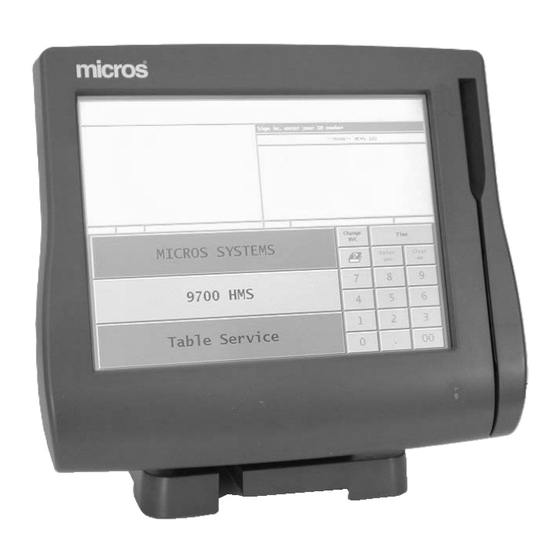
The following section describes the hardware and software features of the Workstation 4. The MICROS Workstation 4 is a diskless Windows CE client, based on a highly integrated AMD Geode SC3200 processor. It is enclosed in a low profile case design with a self-contained power supply. A number of installation, mounting, and customer display options are available, detailed in the following pages. -
Page 13: Compact Flash (Cf) Personality Card
An 802.11b wireless version of the WS4 is available. Reset Switch The Reset Switch can be activated by inserting a paper clip into the access hole. Figure 1-2: The Workstation 4 CF and PCMCIA Slots Workstation 4 Setup Guide... -
Page 14: Workstation Mountnig Options
What is The Workstation 4? The System Workstation Mounting Options A number of mounting options are available for the Workstation 4, as shown in the following pages. The Adjustable Stand The Adjustable Stand, shown in Figure 1-3, converts the low profile WS4 into an adjustable display design. -
Page 15: Wall Mount Bracket
What is The Workstation 4? The System Cable management is accomplished by bundling cables with tie wraps, then routing the bundle through a channel in the stand where they can exit from the side, rear, or bottom as shown in Figure 1-4, below. -
Page 16: Pole Stand
What is The Workstation 4? The System Pole Stand Yet another option for mounting the WS4 is the Pole Mount Stand. On the left of Figure 1-6, the components of the Pole Stand are show, and on the right of the illustration shows the KWS4 mounted on the pole stand. -
Page 17: Adjustable Mounting Arm
What is The Workstation 4? The System Adjustable Mounting Arm The Adjustable Mounting Arm is yet another option for installing the WS4, shown in the illustration below. Figure 1-7: The Adjustable Mounting Arm It can be used to mount the WS4 to a counter surface, wall, or under a shelf. -
Page 18: Customer Display Options
The System Customer Display Options A variety of integrated and pole mount Customer Display options are available for the Workstation 4, described in the following pages. Part Numbers can be found in the WS4 PMA. VFD Customer Display This customer display is composed a 2 Line, 20 Character Vacuum Fluorescent Display (VFD). -
Page 19: Lcd Customer Display
What is The Workstation 4? The System Optional LCD Customer Display A pair of new LCD based Customer Display options are scheduled for release in mid-2004. Each is based on a 240x64 monochrome STN LCD and a companion LCD Control Board. -
Page 20: Software Components
CPU requirements are substantially less than a traditional desktop operating system. POS Application The Workstation 4 is a hardware platform, capable of supporting one of several MICROS POS Applications and possibly third party applications. Throughout this manual, the term ‘POS Application’ is used somewhat generically, and could in fact apply to any of the following software products. -
Page 21: Micros Client Application Loader
MICROS Client Application Loader (CAL) The CAL plays a key role in managing the installation and ongoing maintenance of the Workstation 4 POS application software. The CAL consists of two parts. One part resides on the WS4, (CAL Client) and the second part resides on the system server (CAL Server). -
Page 22: Pos Application Update
What is The Workstation 4? Software Components POS Application Update An update to the POS application becomes available. The updated application files are staged on the system server and the configuration file is modified. Each CAL Client periodically checks with the CAL Server to see if updates are available and recognizes the updated configuration file. -
Page 23: Workstation Personality Swap
Workstation 4 Diagnostics Based on DEMODIAG, the hardware level diagnostics program for the PCWS Eclipse, the Workstation 4 Diagnostics resides on the Disk On Chip in the \Utilities folder. This program is documented in Chapter 4. Workstation 4 Setup Guide... -
Page 24: Memory Architecture
The DOC is currently a 32M device factory populated in a 32-pin Dual In Line Package (DIP) socket. Larger sizes may be used in the future. The DOC represents the non-removable half of the Workstation 4 mass storage solution. Windows CE views the DOC as a Windows file system. In Windows Explorer or My Computer, it appears as ‘\DOC’. -
Page 25: Compact Flash (Cf) Card
What is The Workstation 4? Memory Architecture The contents of this device are shown in Figure 1-13, below. Figure 1-13: WS4 Disk On Chip Contents • The Windows CE .NET image resides in a hidden partition and includes a copy of the default system registry. -
Page 26: Sdram - Working System Ram
What is The Workstation 4? Memory Architecture • Working from left to right in the illustration, the OS update image will be present only if the CAL detects that a newer version of Windows CE has been staged on the system server and places it on the CF Card. - Page 27 Even though the Workstation 4 is diskless in the classical sense, the combination of the Disk On Chip and CF card provide a mass storage solution to preserve application and registry settings that require a lifetime that extends across system reboots.
-
Page 28: Power Managment States
What is The Workstation 4? Power Management States Power Management States This section introduces the Windows CE power management state nomenclature used by the WS4 and describes how each state is displayed on the WS4 Operator LED. References to Windows CE power management states are specified in bold capitol letters, e.g.,... -
Page 29: Workstation 4 Power Management State Table
What is The Workstation 4? Power Management States Workstation 4 Power Management State Table Current Event Source Scenario New State 1-11 State UNPLUGGED NOPOWER AC Power AC Power becomes available and the last recorded state was not the ON or SUSPEND state. -
Page 30: Workstation 4 Power Management State Diagram
What is The Workstation 4? Power Management States Workstation 4 Power Management State Diagram Figure 1-17 shows the workstation power states. Numbers in bubbles correspond to the left column in Figure 1-16. Figure 1-17: WS4 Power Management State Diagram 1-20... -
Page 31: Specifications
What is The Workstation 4? Specifications Specifications The Workstation 4 conforms to the following specifications. Specification Parameters Processor AMD Geode SC3200 WebPad on a Chip Cache 16KB Unified L1 Cache (No L2 Cache) Display 12.1” Active LCD Panel (800x600) Touchscreen... -
Page 32: Approvals
What is The Workstation 4? Approvals Approvals The Workstation 4 meets the following safety and environmental certifications. Expiration Directive Specification Year Comments Date SAFETY : EN60950 2000 7/1/06 EMC : EN 55022 1998 Current A1: 2000 (Radiated) EN 55024 1998... -
Page 33: In This Chapter
In this chapter Disassembling the Workstation 4............2-2 System Board ..................2-7 LCD/Touchscreen and Mag Stripe Reader Assembly ..... 2-14 Hardware Updates................ -
Page 34: Chapter 2 - What's Inside
What’s Inside? Disassembling the Workstation 4 Disassembling the Workstation 4 The following procedure describes how to disassemble the workstation and access the internal components. SHOCK HAZARD When the AC Power Cable is connected to the workstation, hazardous AC and DC voltages are present in the power supply. - Page 35 What’s Inside? Disassembling the Workstation 4 3. Loosen the two captive screws from the under side of the unit as shown in Figure 2-1 4. Remove the top cover from the base. To avoid damaging the hinges on the rear of the base, push the top cover towards the rear of the base a little to release them, then lift up.
- Page 36 What’s Inside? Disassembling the Workstation 4 7. Remove the remaining cables between the top cover and the base. If a Samsung LCD is installed, refer to Figure 2-3. If a Sharp LCD is installed, refer to Figure 2-4. Use a flat bladed screwdriver to release the Magnetic Stripe Reader Cable modular connector from its system board socket.
- Page 37 What’s Inside? Disassembling the Workstation 4 Figure 2-4: Removing Cables from the Top Cover - Sharp LCD 9. Remove the RF shield. First, remove the five screws shown in Figure 2-5 Figure 2-5: Removing the RF Shield screws Workstation 4 Setup Guide...
- Page 38 What’s Inside? Disassembling the Workstation 4 10. Remove the LVDS cable and toroid from the clips on the RF shield. Remove the toroid from the LVDS cable by releasing the latch as shown in Figure 2-6. Figure 2-6: Removing the LVDS Cable from the Toroid 11.
-
Page 39: System Board
This section shows the system board components, connectors, and jumpers. A block diagram and brief technical description is also included. Main Components Figure 2-8 shows the major components of the Workstation 4 system board. Figure 2-8: Workstation 4 System Board - Main Components Workstation 4 Setup Guide... -
Page 40: Connectors
What’s Inside? System Board Connectors Figure 2-9 shows the Workstation 4 System Board connectors. Figure 2-9: Workstation 4 System Board Connectors Workstation 4 Setup Guide... -
Page 41: Jumpers And Switches
What’s Inside? System Board Jumpers and Switches Figure 2-10 points out the system board jumpers and switches. Figure 2-10: System Board Jumpers and Switches Workstation 4 Setup Guide... -
Page 42: Workstation 4 Block Diagram
What’s Inside? System Board Workstation 4 Block Diagram Figure 2-11 shows a block diagram of the Workstation 4, including the system board, internal power supply, as well as the Touch Screen and LCD. Figure 2-11: Workstation 4 Block Diagram Advanced Micro Devices (AMD) Geode SC3200 The SC3200 is now a member of the Advanced Micro Devices (AMD) WebPAD on a Chip family of highly integrated x86 system devices. - Page 43 10BaseT (IEEE 802.3) or 100BaseT (IEEE 802.3u) twisted pair cable interface. • 10/100 Ethernet Controller - Twisted Pair Cabling • PCI Interface with Bus Master Capability • EEPROM stores MAC address and vendor ID data • Wake On LAN Support Workstation 4 Setup Guide 2-11...
- Page 44 Application Loader (CAL) places a copy of the operating system image file (NK.BIN) on the CF card. When the workstation restarts, the Boot Loader detects the file and copies it over the existing OS image on the DOC. 2-12 Workstation 4 Setup Guide...
- Page 45 This device controls the POS features of the workstation including Cash Drawers and Backlight brightness. In addition, it manages the Power and Reset switches, and provides control signals to the on-board power supply regulators to control the WS4 power management states. Workstation 4 Setup Guide 2-13...
-
Page 46: Lcd/Touchscreen And Mag Stripe Reader Assembly
LTM121SI-T01 LCD panel used in production units up to July-August 2004. The lower half shows the replacement, a Sharp LQ121S1LG41. Note the absence of the LVDS receiver board on the Sharp LCD; the equivalent circuitry is built-into the panel. Figure 2-12: Top Cover Assembly 2-14 Workstation 4 Setup Guide... - Page 47 The mag card reader cover is shaped in the form of a trough to divert liquid spills into a slot in the base, away from the system board. Workstation 4 Setup Guide 2-15...
-
Page 48: Hardware Updates
What’s Inside? Hardware Updates Hardware Updates This section includes procedures for removing and replacing the Workstation 4 options. CF Daughter Card The CF Daughter Card is mounted to the base of the workstation with three stand-off, two of which are mounted to the base and the third mounted to system board. -
Page 49: Optional Pcmcia Daughter Card
9. Place the unit face down and connect the antenna to the card. 10. Route the antenna lead through the slot in the bracket supplied in the kit, then install the bracket with two hex screws. Workstation 4 Setup Guide 2-17... -
Page 50: Rear Lcd Customer Display
4. Obtain display interface cable P/N 400416-007. 5. Remove the RF shield cover as described on page 2-2. 6. Attach 400416-007 to System Board connector J1. Figure 2-16. Figure 2-16: Attaching the Rear LCD Cable to the System Board 2-18 Workstation 4 Setup Guide... - Page 51 RES or L&E, however, the 2x20 VFD emulation is supported. Instructions for upgrading the WS4 to the GR1.2 software platform can be found in FB004-001. This document and the GR1.2 software platform files can be found in the hardware support section at www.micros.com. Workstation 4 Setup Guide 2-19...
-
Page 52: Pole Lcd Customer Display
This procedure describes how to install the Pole LCD Customer Display on the Workstation 4. The pole version is provided as a kit consisting of the LCD Display Assembly /w cable, pole, base, extension cable, and nut. Due to the varying thickness and materials used on the counter surface, the installer must provide mounting hardware for the base. - Page 53 POS Applications such as RES or L&E, however, the 2x20 VFD emulation is supported. Instructions for upgrading the WS4 to the GR1.2 software platform can be found in FB004-001. This document and the GR1.2 software platform files can be found in the hardware support section at www.micros.com. Workstation 4 Setup Guide 2-21...
-
Page 54: Disk On Chip
Figure 2-21 show how to use a flat blade screw driver to gently lift one side of the DOC, then the other before removing the DOC from its socket. Figure 2-21: Disk On Chip Removal 2-22 Workstation 4 Setup Guide... -
Page 55: Reassembling The Ws4
The touchscreen extension cable should project from the opening in the front of the shield. The backlight cable should exit the shield through the cut-out on the right side. Figure 2-22: Routing cables through the RF Shield Workstation 4 Setup Guide 2-23... - Page 56 LVDS cable to the LVDS Receiver Board on the Samsung LCD (Figure 2-24), or directly to the Sharp LCD Panel (Figure 2-25), and the Backlight Cable to the Backlight Inverter Board. 2-24 Workstation 4 Setup Guide...
- Page 57 Figure 2-24: Connecting Cables to the Top Cover - Samsung LCD Figure 2-25: Connecting Cables to the Top Cover - Sharp LCD Workstation 4 Setup Guide 2-25...
- Page 58 7. Before closing the cover, place the toroid on the mag stripe reader cable in the cable clamps mounted to the shield. Figure 2-26. Figure 2-26: Securing the Mag Card Reader Cable to the RF Shield 8. Tighten the cover screws to secure the top cover to the base. 2-26 Workstation 4 Setup Guide...
- Page 59 Chapter 3 Installing and Operating the Workstation 4 This chapter describes how to install and the operate the Workstation 4. In this chapter Care and Handling................3-2 The IO Panel..................3-5 Installation ..................3-7 Operation ..................3-10 Personality Swap................3-16 Workstation 4 Setup Guide...
-
Page 60: Care And Handling
Liquid spillage can cause damage to the circuits in the unit. Do not place the equipment near food preparation areas, dish racks, or water stations. The Workstation 4 LCD includes a gasket seal around the touchscreen which may afford some protection from liquid spillage. -
Page 61: Noise Induction
However, tile or anti-static carpet should still be employed in areas near the workstation. Temperature and Humidity The Workstation 4 can operate in temperatures between 32°F and 113°F (0°C to 45°C). A constant humidity between 40% and 90% is required for proper operation of the equipment. -
Page 62: Lcd/Touchscreen
Installing and Operating the Workstation 4 Care and Handling LCD/Touchscreen The touchscreen surface can be cleaned using any common household glass cleaner applied with a clean cotton cloth. Always spray the cloth with the cleaner and then use the cloth to clean the touchscreen. -
Page 63: The Io Panel
Card standard, offering higher levels of performance and conforming to an established physical form factor. Currently, PCMCIA device driver support in Windows CE is limited. Consult the Workstation 4 PMA or your MICROS representative for more information about compatible PCMCIA cards. Compact Flash (CF) The Compact Flash Card (CF) is factory populated on a daughter card and is accessible from the I/O Panel. -
Page 64: Rs232 (Com1)
12Mb per second. All USB devices are plug and play compatible and can be attached to the workstation when the power is on. Consult the Workstation 4 PMA or your MICROS representative for more information about compatible USB devices. Cash Drawers 1 and 2 These connectors support standard and low profile MICROS cash drawers with DIN style connectors. -
Page 65: Installation
Installing and Operating the Workstation 4 Installation Installation This section discusses the recommended method of cabling the workstation when used with the Adjustable Stand. Cabling the Workstation This procedure describes how to cable the WS4 and attach it to the optional adjustable stand. - Page 66 Installing and Operating the Workstation 4 Installation 3. Line the four inside plastic hooks on the workstation with the four rectangular holes on the stand and place the unit on the stand as shown in Figure 3-2. The workstation will slide down and lock into place.
- Page 67 Installing and Operating the Workstation 4 Installation 6. Connect the AC power cord to an electrical outlet installed in accordance with the appropriate site prep guide. See the Starting the Workstation for the first time procedure. Workstation 4 Setup Guide...
-
Page 68: Operation
NOPOWER SUSPEND power states. Figure 3-4 points out the location of the Workstation 4 Power Switch, Operator LED, Magnetic Card Reader, and the Operator LCD. Figure 3-4: Workstation 4 Operator Features Operator LCD The Operator LCD is an 12.1”... -
Page 69: Turning The Workstation From Nopower To On
Figure 3-5. A progress bar centered under the logo indicates that the workstation is proceeding with the boot process. The Windows CE operating system will start in approximately 60 seconds. Figure 3-5: Workstation 4 Boot Splash Screen • When the workstation completes booting to the operating system, the Operator LED turns solid Green. -
Page 70: Starting The Workstation For The First Time
1. Double click the server entry. This will connect you to the device database and display a list of pre-programmed Workstation 4s. See your application programming documentation. 2. Select your Workstation 4 from the list. Double-click the entry. • Each workstation is pre-programmed with a workstation name, IP address, and other application related settings. -
Page 71: Using The Magnetic Strip Card
Using the Magnetic Stripe Card The Workstation 4 Magnetic Stripe Reader is mounted on the right side of the top cover as shown in Figure 3-6, below. A symbolic representation of how the card should be inserted is embossed on the cover. -
Page 72: Getting To Know The Compact Flash Card
A CF Card must be installed or the WS4 will not start. A POST error will occur. See Chapter 4. • The Workstation 4 currently ships with a 64M CF Card. Larger sizes can be used, but please check the Approved CF Card List on the Hardware Support section of the web site. -
Page 73: Calibrating The Touchscreen
Installing and Operating the Workstation 4 Operation Calibrating The Touchscreen Calibrating the touchscreen is the process of aligning the touchscreen glass with the underlying video display. When to Calibrate the Touchscreen • When installing a new workstation. The first time a WS4 is powered up from the factory, the Touchware Properties Utility starts. -
Page 74: Personality Swap
If required, see page 3-14 to learn more about the CF card. Tools Required • 2.5mm hex wrench. Included with each Workstation 4 in the loose parts kit. • Small or Medium Wire Cutters. Most installations use tie wraps to secure cables to the cable cleats at the I/O panel. - Page 75 Installing and Operating the Workstation 4 Personality Swap 3. Insert the hex wrench into the bracket screws and turn it counter clock-wise to remove each screw. 4. Remove the bracket. Set the bracket and screws aside for the moment. •...
- Page 76 Installing and Operating the Workstation 4 Personality Swap To assist in orienting the card as you install it, a label similar to that shown in Figure 3-9 will be added to the CF card after July 2003. Note the arrow showing the proper orientation of the card.
- Page 77 Installing and Operating the Workstation 4 Personality Swap 7. Install the personality card removed from the inoperative WS4. Refer to Figure 3-11, it displays a series of illustrations describing how insert the card. Figure 3-11: Inserting the CF Card Workstation 4 Setup Guide...
- Page 78 Installing and Operating the Workstation 4 Personality Swap Starting at the top of Figure 3-11, position the CF card as shown with the lip and label facing you, then insert it into the guides. When the card is properly aligned in the guides as shown in the middle illustration, rotate it to the position shown in the middle illustration, then push the card in until it is fully inserted.
-
Page 79: Chapter 4 - Workstation 4 Diagnostics
Chapter 4 Workstation 4 Diagnostics This chapter includes diagnostics information on the Workstation 4. In this chapter Basic Troubleshooting ............... 4-2 Power On-Self Test (POST) Errors............ 4-3 Workstation 4 Diagnostics Utility............4-5 Workstation 4 Setup Guide... -
Page 80: Basic Troubleshooting
Workstation 4 Diagnostics Basic Troubleshooting Basic Troubleshooting This section provides a brief troubleshooting chart for the Workstation 4. Problem Possible Cause Solution WS4 is dead. Operator LED No Power to WS4 Be sure AC power cable is Indicator is Off. Operator... -
Page 81: Power On Self Test (Post) Errors
DOC present, but OS image not found Solid Short-Long-Short Missing or defective DOC 0.25Hz Short-Short Missing Compact Flash Card 0.25Hz Long-Short Defective SDRAM (DIMM1) 0.25Hz Short-Long Defective Touchscreen Controller U40 0.25Hz Long-Short-Long Defective EEPROM U21 0.25Hz Long-Long PCI Bus Error 0.25Hz Workstation 4 Setup Guide... - Page 82 This error indicates a problem was found on the PCI Bus and could point to any of the following devices. • Ethernet Controller and Serial EEPROM. • USB Controller. • TFT Video Controller. • IDE Controller. • Audio Controller. Workstation 4 Setup Guide...
-
Page 83: Workstation 4 Diagnostics Utility
Workstation 4 Diagnostics Utility Workstation 4 Diagnostics Utility The Workstation 4 includes a diagnostics utility located on the Disk On Chip. Based on the DEMODIAG utility found in the MICROS PC Workstations, the WS4 Diagnostics Utility includes a comprehensive test of the internal hardware and peripherals including IDN printing devices. -
Page 84: The System Information Screen - Hardware Components
Workstation 4 Diagnostics Workstation 4 Diagnostics Utility System Information Screen - Hardware Components When the WS4 Diagnostics Utility is started, it displays the System Information screen, shown in Figure 4-1, below. The following section details each of the hardware components found on this screen. - Page 85 Workstation 4 Diagnostics Workstation 4 Diagnostics Utility CPU Type All current and future Workstation 4 system boards run the AMD Geode SC3200. AMD purchased the National Semiconductor Corp. Geode embedded processor line in 2003. RAM Space Available This field displays the amount of available RAM, located in the single DIMM installed on the system board.
- Page 86 Workstation 4 Diagnostics Workstation 4 Diagnostics Utility CF Space Available This field displays the space available on the CF Card. The value displayed on your WS4 will not always agree with that shown. Figure 4-1 displays the available space on a factory fresh 64M CF card before the POS application and support files are installed.
- Page 87 Figure 4-2: The System Information Screen (Software Platform GR 1.0) UWS4.DLL This file contains the Workstation 4 API, or Application Programming Interface. POS Applications use the API to access hardware such as the Cash Drawers, Mag Stripe Reader, and IDN Interface. The GR 1.2 platform updates uws4.dll with many new features to support the graphics based LCD customer...
- Page 88 Workstation 4 Diagnostics Workstation 4 Diagnostics Utility PRD.DLL The PRD, or Persistent Registry Driver manages the WS4 persistent registry. When the workstation boots and starts WinCE, the PRD retrieves the persistent registry from the CF Card and places it in RAM as the working registry. As the...
- Page 89 Workstation 4 Diagnostics Workstation 4 Diagnostics Utility To use the soft keyboard, touch the pencil icon once, then touch the ‘LargeKB’ entry from the menu that appears. The keyboard can be repositioned by pressing and holding the gray bar at the top of the keyboard with your finger, and dragging it to the desired position.
-
Page 90: Workstation 4 Wipe Compact Flash (Wcf) Utility
Workstation 4 Diagnostics Workstation 4 Wipe Compact Flash (WCF) Utility Workstation 4 Wipe Compact Flash (WCF) Utility In addition to the Diagnostics Utility, the \DOC\Utilies folder also contains WCF.EXE, the Wipe Compact Flash utility. Originally developed for the WS4 production line, it has also been useful during the initial testing of Windows CE and POS Applications. - Page 91 POS features of the Workstation 4. For example, to open a cash drawer, the programmer calls an API function.
- Page 92 LED and controlling backlight brightness. Abbreviation for Client Application Loader. The MICROS CAL is a software utility that assists in the installation of the Workstation 4 application software, then manages the ongoing maintenance of the operating system and application software. The CAL consists of two parts, one part resides on the WS4 client and the second part resides on the system server.
- Page 93 WS4 Glossary CF cards are available in sizes ranging from 8M to 1G. The Workstation 4 currently uses a 32M CF Card installed in an accessible but secure location near the I/O panel connector. Larger sizes may used in the future. In the WS4 memory architecture, the CF card contains workstation 4 ‘personality’.
- Page 94 LEDs are available in many colors including IR, and are typically used as power or status indicators. The Workstation 4 Operator LED is a two color device, modified to display Green, Amber, and Red colors. Each of the three colors can be combined with 4 unique blink rates to provide twelve discreet indications.
- Page 95 Abbreviation for Magnetic Stripe Reader. An MSR contains a transducer that reads the data from multiple tracks on a mag stripe card. The workstation 4 is equipped with a 3-track MSR. See also: MAGTEK Mode and Special Mode. MAGTEK Mode MAGTEK mode emulates the output from the MAGTEK series of card readers manufactured by MAGTEK, Inc.
- Page 96 A generic term for a device that stores information in a form that the CPU can recognize and manipulate. Memory appears in several forms, each of which has a specific role in the Workstation 4. A distinction must be made between the primary and secondary storage in microprocessor based systems.
- Page 97 USB ports. POST Abbreviation for Power On Self Test. In the Workstation 4, the POST is built into the Boot Loader, which executes each time the workstation is powered up. It checks for the presence of the Disk On Chip and Compact Flash Card, checks several key hardware circuits.
- Page 98 Electronics Industry Association and Telecommunications Industry Association. A full-duplex version of RS422 is used by the Workstation 4 to drive IDN printing devices. The workstation has two RS422 ports. Abbreviation for Real Time Clock. The RTC is connected to a battery and separate crystal oscillator to maintain time-keeping when the workstation is unplugged or turned-off.
- Page 99 MSR data for processing. See Also: MAGTEK Mode. System Board The motherboard or mainboard for the Workstation 4. The System Board contains the majority of the workstation circuitry including the CPU, Chipset, SDRAM, Disk On Chip, Compact Flash, and Input/Output Ports.
- Page 100 1.5MB/s or 12 MB/s over a daisy chain of up to 128 peripheral devices. The WS4 includes two USB 1.0 compatible ports. Currently, only a USB keyboard and mouse are supported. Glossary-10 Workstation 4 Setup Guide...
- Page 101 Equipment Dimensions In this appendix Workstation 4 - Low Profile ............A-2 Workstation 4 - LP /w Integrated LCD Customer Display ..A-3 Workstation 4 on Adjustable Stand ..........A-4 WS4 on Adjustable Stand with Rear LCD Customer Display..A-5 Workstation 4 on Adjustable Stand /w VFD Customer Display .. A-6 Workstation 4 on Wall Mount Stand..........
-
Page 102: Workstation 4 - Low Profile
Equipment Dimensions Workstation 4 - Low Profile Workstation 4 - Low Profile Workstation 4 Setup Guide... -
Page 103: Workstation 4 - Low Profile With Rear Lcd Customer Display
Equipment Dimensions Workstation 4 - Low Profile with Rear LCD Customer Display Workstation 4 - Low Profile with Rear LCD Customer Display Workstation 4 Setup Guide... -
Page 104: Workstation 4 On Adjustable Stand
Equipment Dimensions Workstation 4 on Adjustable Stand Workstation 4 on Adjustable Stand Workstation 4 Setup Guide... -
Page 105: Ws4 On Adjustable Stand With Rear Lcd Customer Display
Equipment Dimensions WS4 on Adjustable Stand with Rear LCD Customer Display WS4 on Adjustable Stand with Rear LCD Customer Display Workstation 4 Setup Guide... -
Page 106: Workstation 4 On Adjustable Stand With Vfd Pole Display
Equipment Dimensions Workstation 4 on Adjustable Stand with VFD Pole Display Workstation 4 on Adjustable Stand with VFD Pole Display Workstation 4 Setup Guide... -
Page 107: Workstation 4 On Wall Mount Stand
Equipment Dimensions Workstation 4 on Wall Mount Stand Workstation 4 on Wall Mount Stand Workstation 4 Setup Guide... -
Page 108: Lcd Pole Display
Equipment Dimensions LCD Pole Display LCD Pole Display Workstation 4 Setup Guide... -
Page 109: Cash Drawer
Equipment Dimensions Cash Drawer Cash Drawer Workstation 4 Setup Guide... -
Page 110: Cash Drawer, Low Profile
Equipment Dimensions Cash Drawer, Low Profile Cash Drawer, Low Profile A-10 Workstation 4 Setup Guide... -
Page 111: Vfd Pole Display
Equipment Dimensions VFD Pole Display VFD Pole Display Workstation 4 Setup Guide A-11... - Page 112 Equipment Dimensions VFD Pole Display A-12 Workstation 4 Setup Guide...
-
Page 113: Appendix B: Connector And Cable Diagrams
4 I/O Panel connectors, system board connectors, and commonly used hook-up cables. A description of how each cable or connector is used is provided. In this appendix IO Panel Connectors ...............B-2 System Board Connectors.............. B-7 Hook-up Cables ................B-8 Workstation 4 Setup Guide... -
Page 114: Io Panel Connectors
The following connectors are located on the WS4 IO Panel. RS422-A (COM4) and RS422-B (COM5) The Workstation 4 includes a pair of these connectors wired identically. Each may be used in one of three different configurations, two for RS422 and one for RS232. -
Page 115: Lcc
8700 installations was pending at the time this manual was released. Figure B-2: LCC Connector Configured in LCC(-) mode RS232 The RS422-A (COM4) and RS422-B (COM5) ports include a basic RS232 interface. This configuration is shown in below. Figure B-3: LCC Port Configured for RS232 Workstation 4 Setup Guide... -
Page 116: 10/100 Ethernet Connector
The pin-out for the 10/100 Ethernet port is shown in Figure B-4, below. Figure B-4: 10/100 Ethernet Connector Diagram RS232 Connector A single DB9F RS232 connector assigned to COM1 is provided. The pin-out is shown below. Figure B-5: DB9 RS232 Connector Diagram Workstation 4 Setup Guide... -
Page 117: Usb Connectors
USB Connectors A pair of USB ports are located on the IO panel, shown in Figure B-6, below. Figure B-6: Universal Serial Bus Connector Diagram Cash Drawer 1 and 2 Connectors Figure B-7: Cash Drawer Connector Diagram Workstation 4 Setup Guide... -
Page 118: Ps2 Mouse/Keyboard Connectors
PS2 Mouse/Keyboard Connectors Figure B-8: PS2 Mouse and Keyboard Connector Diagrams Remote Customer Display Connector This port supports either the 2x20 VFD customer display or the graphics based LCD customer display. Figure B-9: Customer Display Connector Diagram Workstation 4 Setup Guide... -
Page 119: System Board Connectors
Connector and Cable Diagrams System Board Connectors System Board Connectors This section details connectors located on the Workstation 4 system board. Magnetic Stripe Interface The internal magnetic card reader connector is CN10, located on the system board. The pin-outs for this connector are shown in Figure B-10,... -
Page 120: Hook-Up Cables
Hook-up Cables The following pages show wiring diagrams of various hook-up cables that may be used with the Workstation 4. RS232 from the RS422-A and RS422-B Ports Figure B-11 shows a cable that includes the RS232 signals from RS422-A and RS422-B ports to a DB9 male connector. -
Page 121: Lcd Customer Display Cables
When the LCD customer display is attached directly to the rear of the workstation, this cable plugs into the system board cable shown in Figure B-13. When the LCD customer display assembly is mounted on the pole, this cable attaches to the cable shown in Figure B-15, below. Workstation 4 Setup Guide... -
Page 122: Remote Pole Lcd Customer Display
Display kit. It attaches between the 4-pin DIN customer display connector on a WS4 or KWS4 IO Panel, up through the pole to mate with the cable from the LCD Display Assembly shown in Figure B-14. Figure B-15: Remote Pole LCD Customer Display Assembly B-10 Workstation 4 Setup Guide... -
Page 123: Ethernet
Figure B-16 shows a diagram of a standard Cat 5 Ethernet hook-up cable. This cable would be connected from a workstation or server to the system hub. Figure B-16: EIA/TIA-568-A Cat 5 Ethernet Hook-up Cable Diagram Workstation 4 Setup Guide B-11... - Page 124 This cable can be used when only two devices must be connected. For example it can be used to connect two workstations, or a server connected to a single client. Figure B-17: Cat 5 Ethernet Hook-up Cable Diagram (cross-over) B-12 Workstation 4 Setup Guide...
-
Page 125: 8-Pin To 6-Pin Hook-Up Rs422 Cable (300319-001
This cable brings out the RS422 signals from the 8-pin LCC/RS232 connector to a 6-pin wall plate or directly to the 6-pin connector located on the IDN device. Figure B-18: 8-Pin to 6-Pin RS422 Hook-up Cable Diagram Workstation 4 Setup Guide B-13... -
Page 126: Cash Drawer Extension Cable
Connector and Cable Diagrams Hook-up Cables Cash Drawer Extension Cable B-14 Workstation 4 Setup Guide... -
Page 127: Appendix C: Fcc/Doc Statement
If this equipment appears to cause interference the user could consult the installer/dealer or an experienced radio television technician. Workstation 4 Setup Guide... - Page 128 A booklet prepared by the Federal Communications Commission entitled "How to Identify and Resolve Radio - TV Interference Problems" may be useful. This booklet may be ordered from the Superintendent of Documents, U.S. Government Printing Office, Washington D.C. with stock number #004-000-00345-4.
Need help?
Do you have a question about the Workstation 4 and is the answer not in the manual?
Questions and answers