Sign In
Upload
Manuals
Brands
MICRO-EPSILON Manuals
Accessories
IFD2410-3
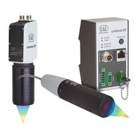
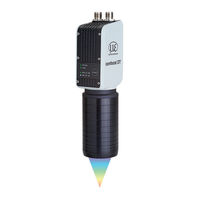
MICRO-EPSILON IFD2410-3 Distance Sensor Manuals
Manuals and User Guides for MICRO-EPSILON IFD2410-3 Distance Sensor. We have
2
MICRO-EPSILON IFD2410-3 Distance Sensor manuals available for free PDF download: Operating Instructions Manual, Quick Manual
MICRO-EPSILON IFD2410-3 Operating Instructions Manual (178 pages)
Brand:
MICRO-EPSILON
| Category:
Measuring Instruments
| Size: 21 MB
Table of Contents
Table of Contents
3
1 Safety
9
Symbols Used
9
Warnings
9
Notes on Product Marking
10
Notes on CE Marking
10
Notes on UKCA Marking
10
Intended Use
10
Proper Environment
10
2 Functional Principle, Technical Data
11
Short Description
11
Measuring Principle
11
Term Definitions, Glossary
12
Technical Data for Confocaldt IFD2410/2415
13
Technical Data Confocaldt IFD2411
14
3 Delivery
15
Scope of Delivery Confocaldt IFD2410/2415
15
Scope of Delivery Confocaldt IFD2411
15
Storage
15
4 Mounting
16
Preliminary Remarks
16
Confocaldt IFD2410/2415
16
Circumferential Clamping
16
Direct Screw Connection
17
Electrical Connections, Pin Assignment
18
Grounding Concept, Shielding
19
Supply Voltage (Power)
19
Rs422
20
Ethernet, Ethercat
20
Analog Output
21
Multifunction Inputs
21
Switching Outputs (Digital I/O)
22
Synchronization (Inputs/Outputs)
23
4.2.11.1 General
23
4.2.11.2 Internal Synchronization
23
4.2.11.3 External Synchronization
24
Triggering
25
4.2.12.1 General
25
4.2.12.2 Triggering with Multifunction Input
25
4.2.12.3 Triggering with Synchronization Input
25
Triggering with Input Encoder 1
25
Encoder Inputs
26
Confocaldt 2411
27
IFC2411 Controller
27
Sensor Cable, Optical Fiber
27
Dimensional Drawing of Sensors
29
Fastening, Mounting Adapter
29
General
29
Circumferential Clamping
29
Electrical Connections, Pin Assignment
31
Grounding Concept, Shielding
31
Supply Voltage (Power)
32
Rs422
32
Ethernet, Ethercat
32
Analog Output
33
Multifunction Input
33
Synchronization (Inputs/Outputs)
34
4.3.12.1 General
34
4.3.12.2 Internal Synchronization
34
4.3.12.3 External Synchronization Controller
35
Triggering
36
4.3.13.1 General
36
4.3.13.2 Triggering with Multifunction Input
36
4.3.13.3 Triggering with Synchronization Input
36
Triggering with Input Encoder 1
37
Encoder Input
37
Handling of the Plug-In Screw Terminals
37
Dark Correction IFD2415
37
Leds
38
Correct and Multifunction Key
38
5 Commissioning
39
Communication Options
39
Access Via Web Interface
40
Positioning the Target
41
Select Sensor
41
Presets, Setups, Measurement Configuration Selection
42
Video Signal
43
Signal Quality
44
Distance Measurement with Website Display
45
Save/Load Settings
47
Dark Correction
49
6 Set Sensor Parameters, Web Interface
51
Inputs
51
Synchronization
51
Encoder Inputs
51
Overview, Menu
51
Number of Encoders
51
Interpolation
52
Maximum Value
52
Effect of Reference Track
52
Set to Value
52
Reset Reference Marker
52
Level Function Inputs
53
Terminating Resistor
53
Data Recording
54
Measuring Rate
54
Triggering Data Acquisition
55
General
55
Triggering Measured Value Acquisition
55
Trigger Time Difference
56
Reset Counter
56
Range of Interest Masking
56
Exposure Mode
57
Peak Separation
58
Peak Modulation
58
Detection Threshold
58
Number of Peaks, Peak Selection
59
Material Selection
60
Signal Processing, Calculation
61
Data Source, Parameters, Calculation Programs
61
Definitions
62
Measurement Averaging
63
Post-Processing
66
Zeroing, Mastering
66
Statistics
68
Data Reduction, Output Data Rate
69
Error Handling (Hold Last Value)
69
Outputs
70
Interface RS422
70
Ethernet Setup Mode
70
Rs422
70
Analog Output
71
Calculating Measured Value from Current Output
71
Calculation Measured Value from Voltage Output
72
Data Output
72
System Settings
73
Web Interface Unit
73
Key Lock
73
Loading and Saving
73
Access Authorization
73
Reset System
74
Light Source
74
Boot Mode
74
7 Thickness Measurement, One-Sided, Transparent Target
75
Requirement
75
Preset
75
Material Selection
75
Video Signal
76
Signal Processing
76
Measurement Chart
77
8 Ethercat Documentation
78
General
78
Introduction
78
Structure of Ethercat® Frames
78
Ethercat® Services
78
Addressing and Fmmus
79
Sync Manager
79
Ethercat State Machine
79
Canopen over Ethercat
80
Process Data PDO Mapping
80
Service Data SDO Service
80
Coe - Object Directory
81
Communication Specific Standard Objects
81
Overview
81
Object 1001H: Device Type
81
Object 1008H: Manufacturer Device Name
81
Object 1009H: Hardware Version
81
Object 100Ah: Software Version
81
Object 1018H: Device Identification
81
Txpdo Mapping IFD2410, 2411
82
Txpdo Mapping IFD2415
91
Example of Txpdo Mapping
104
8.3.1.10 Object 1C00H: Synchronous Manager Type
105
8.3.1.11 Object 1C12H: Rxpdo Assign
105
8.3.1.12 Object 1C13H: Txpdo Assign
105
8.3.1.13 Object 1C32H: Sync Manager Output Parameters
106
8.3.1.14 Object 1C33H: Sync Manager Input Parameters
106
Manufacturer Specific Objects
107
Overview
107
Object 3001H: User Level
108
Object 3005H: Information on the Ifd241X (Further)
108
Object 3011H: Correction, Channel 1
108
Object 3020H: Load, Save, Factory Setting
109
Object 3021H: Preset
109
Object 3022H: Measurement Settings
109
Object 303Fh: Error Ifd241X
110
Object 3101H: Reset
110
8.3.2.10 Object 3105H: Factory Settings
110
8.3.2.11 Object 3107H: Reset Counter
110
Object 3133H: LED Light Source Channel 1
110
Object 3150H: Error Ifd241X Channel 1
110
Object 3152H: Sensor Selection Channel 1
111
8.3.2.15 Object 3153H: Sensor Table
111
Object 3156H: Multilayer Options for Channel 1
111
Object 3161H: Peak Selection Channel 1
111
Object 3162H: Peak Options Channel 1
112
8.3.2.19 Object 31B0H: Digital Interfaces
112
8.3.2.20 Object 31B1H: Interface Selection
112
8.3.2.21 Object 31B2H: Error Handling
112
8.3.2.22 Object 31B3H: Data Reduction
112
8.3.2.23 Object 31D0H: Analog Output
113
Object 31F3H: Switching Output 1
114
8.3.2.25 Object 31F5H: RS422 Output
115
Object 3250H: Exposure Mode Channel 1
115
8.3.2.27 Object 3251H: Measuring Rate
115
8.3.2.28 Object 34A0H: Keylock
115
8.3.2.29 Object 35A0H: Encoder
116
8.3.2.30 Object 35B0 Triggering
116
8.3.2.31 Object 35B1 Synchronization
117
Object 3711H: Range of Interest Masking Channel 1
117
8.3.2.33 Object 3800H: Material Information
117
8.3.2.34 Object 3802H: Edit Material Table
118
8.3.2.35 Object 3803H: Existing Materials
118
Object 3804H: Select Material for Channel 1
118
8.3.2.37 Object 3A00H: Mastering, Zeroing
118
8.3.2.38 Object 3A10H: Statistics
119
Object 3C00H: Measured Value Calculation Channel 1
120
8.3.2.40 Object 3Cbfh: Sys Signals
121
8.3.2.41 Object 3E00: User Signals
121
Mappable Objects - Process Data
122
Object 6000, 6001: Distance Value
122
Object 6010, 6011: Intensity
122
Object 6030: Exposure Time
123
Object 6050, 6051, 6052: Encoder
123
Object 6060: Peak Symmetry
123
Object 7000: Measured Value Counter
124
Object 7001: Timestamp
124
Object 7002: Measuring Rate
124
Object 7C00: Calculated Process Data
125
Error Codes for SDO Services
125
Oversampling
126
Calculation
128
Setting a Filter
128
Thickness Calculation
128
Operational Modes
129
Free Run
129
Distributed Clocks SYNC0 Synchronization
129
SM2/SM3 Synchronization
129
Update
129
Update Via Foe
129
Update Via Eoe
129
Meaning of Leds in Ethercat Operation
130
Ethercat Configuration with the Beckhoff Twincat© Manager
131
9 Error, Repair
133
Web Interface Communication
133
Changing the Sensor Cable on the Sensors
133
Replacing the Protective Glass on the Sensors
133
10 Software Support with Medaqlib
134
11 Disclaimer
134
12 Service, Repair
135
13 Decommissioning, Disposal
136
Appendix
137
A 1 Optional Accessories, Services
137
A 1.1 Optional Accessories Confocaldt IFD2410/2415
137
A 1.2 Optional Accessories Confocaldt IFD2411
137
A 1.3 Services
137
A 2 Factory Settings
138
A 2.1 Confocaldt IFD2410/2415
138
A 2.2 Confocaldt IFD2411
138
A 3 Adjustable Mounting Adapter JMA-XX
139
A 3.1 Functions
139
A 3.2 Sensor Mounting, Compatibility
139
A 3.3 Mounting
139
A 3.4 Dimensional Drawing of Mounting Adapter
139
A 3.5 Perpendicular Alignment of Sensor
140
A 4 Cleaning Optical Components
141
A 4.1 Contamination
141
A 4.2 Tools and Cleaning Agents
142
A 4.3 Sensor Protective Glass
142
A 4.4 Interface between Controller and Sensor Cable
143
A 4.5 Interface between Sensor Cable and Sensor
144
A 4.6 Preventive Protection
144
A 5 ASCII Communication with Controller
145
A 5.1 General
145
A 5.2 Commands Overview
145
A 5.3 General Commands
148
General
148
A 5.3.1.1 Help
148
Controller Information
148
Reply Type
148
Parameter Overview
148
A 5.3.1.5 Synchronization
149
A 5.3.1.6 Termination Resistor at Sync/Trig
149
A 5.3.1.7 Boot Sensor
149
A 5.3.1.8 Reset Counter
149
A 5.3.2 User Level
150
A 5.3.2.1 Change User Level
150
A 5.3.2.2 Switch to User Level
150
A 5.3.2.3 User Level Query
150
A 5.3.2.4 Set Standard User
150
A 5.3.2.5 Change Password
150
A 5.3.3 Level of Multifunction Inputs
150
Sensor
151
A 5.3.4.1 Information on Calibration Tables
151
A 5.3.4.2 Sensor Information
151
Dark Correction
151
Led
151
A 5.3.4.5 Control Input Measurement Light Source
151
Triggering
152
A 5.3.5.1 Select Trigger Source
152
A 5.3.5.2 Output of Triggered Values, With/Without Averaging
152
Trigger Type
152
A 5.3.5.4 Active Level of Trigger Input
152
A 5.3.5.5 Software Trigger Pulse
152
A 5.3.5.6 Number of Measured Values to be Output
152
A 5.3.5.7 Level Section Trigger Input Trigin
153
A 5.3.5.8 Step Size Encoder Triggering
153
A 5.3.5.9 Minimum Encoder Triggering
153
A 5.3.5.10 Maximum Encoder Triggering
153
Encoder
153
A 5.3.6.1 Number of Available Encoders
153
A 5.3.6.2 Encoder Interpolation Depth
153
A 5.3.6.3 Effect of Reference Track
153
A 5.3.6.4 Encoder Value
154
A 5.3.6.5 Set Encoder Value Via Software
154
A 5.3.6.6 Reset Detection of First Reference Marker
154
A 5.3.6.7 Maximum Encoder Value
154
A 5.3.6.8 Number of Active Encoders
154
A 5.3.7 Setting the RS422 Baud Rate
155
A 5.3.8 Parameter Management, Load/Save Settings
156
A 5.3.8.1 Load / Save Connection Settings
156
A 5.3.8.2 Show Changed Parameters
156
A 5.3.8.3 Export Parameter Sets to PC
156
A 5.3.8.4 Import Parameter Sets from PC
156
Factory Settings
156
A 5.3.8.6 Editing, Storing, Displaying, Deleting Measurement Settings
157
A 5.3.9 Measurement
157
A 5.3.9.1 Peak Count
157
A 5.3.9.2 Peak Selection
157
A 5.3.9.3 Number of Peaks and Switching Refractivity Correction On/Off
158
A 5.3.9.4 Exposure Mode
158
A 5.3.9.5 Measuring Rate
158
A 5.3.9.6 Exposure Time
158
A 5.3.9.7 Range of Interest (ROI)
158
A 5.3.9.8 Minimum Threshold Peak Detection
158
Peak Modulation
159
A 5.3.10 Material Database
159
A 5.3.10.1 Material Table
159
A 5.3.10.2 Select Material
159
A 5.3.10.3 Show Material Property
159
A 5.3.10.4 Existing Material in Controller
159
A 5.3.10.5 Protected Materials in Controller
159
A 5.3.10.6 Edit Material Table
160
A 5.3.10.7 Delete a Material
160
A 5.3.10.8 Add Material
160
A 5.3.11 Edit Measured Value
160
A 5.3.11.1 Statistical Calculations
160
A 5.3.11.2 List of Statistics Signals
160
A 5.3.11.3 Selection of Statistics Signal
161
A 5.3.11.4 List of Possible Statistics Signals to Select
161
A 5.3.11.5 List of Possible Signals to be Parameterized
161
A 5.3.11.6 Parameterization of Master Signals
161
A 5.3.11.7 List of Possible Signals for Mastering
161
A 5.3.11.8 Mastering / Zeroing
161
A 5.3.11.9 Signal for Mastering with External Source
162
A 5.3.11.10 Mastering with External Source
162
A 5.3.11.11 Example of Mastering
162
A 5.3.11.12 Calculation in Channel
164
A 5.3.11.13 List of Possible Calculation Signals
164
A 5.3.11.14 Two-Point Scaling Data Outputs
164
A 5.3.12 Data Output
165
A 5.3.12.1 Digital Output Selection
165
A 5.3.12.2 Output Data Rate
165
A 5.3.12.3 Reduction Counter for Output of Measured Values
165
A 5.3.12.4 Error Handling
165
A 5.3.13 Selection of Measured Values to be Output
166
A 5.3.13.1 General
166
A 5.3.13.2 Data Selection for RS422
166
A 5.3.13.3 List of Possible Signals for RS422
166
A 5.3.13.4 List of Selected Signals, Sequence Via Rs422
166
A 5.3.14 Switching Outputs
166
A 5.3.14.1 General
166
A 5.3.14.2 Error - Switching Outputs
166
A 5.3.14.3 List of Possible Signals for Error Output
166
A 5.3.14.4 Set Signal to be Evaluated
166
A 5.3.14.5 Set Limit Values
167
A 5.3.14.6 Set Value
167
A 5.3.14.7 Switching Behavior of Error Outputs
167
A 5.3.14.8 Switching Hysteresis of Error Outputs
167
A 5.3.15 Analog Output
167
A 5.3.15.1 Data Selection
167
A 5.3.15.2 List of Possible Signals for Analog Output
167
A 5.3.15.3 Output Range
167
A 5.3.15.4 Set Scaling for DAC
168
A 5.3.15.5 Set Scaling Range
168
A 5.3.16 System Settings
168
A 5.3.16.1 Key Lock
168
A 5.3.16.2 Switch Ethercat to Ethernet Setup Mode
168
A 5.4 Measured Value Format
169
A 5.4.1 Structure
169
A 5.4.2 Video Signal
169
A 5.4.3 Exposure Time
169
A 5.4.4 Encoder
169
A 5.4.5 Measured Value Counter
170
Timestamp
170
A 5.4.7 Measuring Data (Distances and Intensities)
170
A 5.4.8 Trigger Time Difference
170
A 5.4.9 Differences (Thicknesses)
170
A 5.4.10 Statistical Values
170
A 5.4.11 Peak Symmetry
170
A 5.5 Measuring Data Formats
171
A 5.5.1 Data Format RS422 Interface
171
A 5.5.1.1 Video Data
171
Measured Values
171
A 5.6 Warning and Error Messages
173
A 6 Switch between Ethercat and Ethernet Setup Mode
175
A 7 Switching between Ethernet Setup Mode and Ethercat
175
Telnet
176
General
176
A 8.2 Establishing the Connection
176
A 8.3 Help on a Command
177
A 8.4 Error Messages
177
Advertisement
MICRO-EPSILON IFD2410-3 Quick Manual (28 pages)
Brand:
MICRO-EPSILON
| Category:
Accessories
| Size: 3 MB
Table of Contents
Table of Contents
2
General
3
Symbols Used
3
Warnings
3
Intended Use
4
Proper Environment
4
Glossary
4
Mechanical Fastening
5
Preliminary Remarks
5
Circumferential Clamping
5
Direct Fastening
6
Electrical Connections
7
Supply Voltage
9
RS422 Connection with USB Converter IF2001/USB
9
Sensor Leds
10
Correct Button
11
Start of Measuring Range
11
Initial Operation
12
Switch between Ethercat and Ethernet Setup Mode
13
Access Via Web Interface
14
Positioning the Target
15
Presets, Setups, Measurement Configuration, Signal Quality
16
Checking the Video Signal, Peak Selection
18
Distance Measurement with Website Display
19
One-Sided Thickness Measurement, Transparent Target
21
Preset Selection
21
Material Selection
21
Video Signal
22
Measurement Chart for Thickness Measurement
23
Switch between Ethernet Setup Mode and Ethercat
24
Ethercat
25
Preliminary Remarks
25
Parameter Setting Via Ethercat
25
Saving the Settings, Continuing Ethercat Mode
26
Service, Repair
27
Disclaimer
27
Decommissioning, Disposal
28
Advertisement
Related Products
MICRO-EPSILON IFD2410-1
MICRO-EPSILON IFD2410-6
MICRO-EPSILON IFD2415-1
MICRO-EPSILON IFD2415-3
MICRO-EPSILON IFD2415-10
MICRO-EPSILON ILD1700-20LL
MICRO-EPSILON ILD2200-10
MICRO-EPSILON optoNCDT ILR 110 series
MICRO-EPSILON ILD2300-20LL
MICRO-EPSILON ILD2310-50BL
MICRO-EPSILON Categories
Measuring Instruments
Accessories
Industrial Equipment
Controller
Security Sensors
More MICRO-EPSILON Manuals
Login
Sign In
OR
Sign in with Facebook
Sign in with Google
Upload manual
Upload from disk
Upload from URL