
Related Manuals for MICRO-EPSILON confocalDT 2410 EtherCAT


Summary of Contents for MICRO-EPSILON confocalDT 2410 EtherCAT
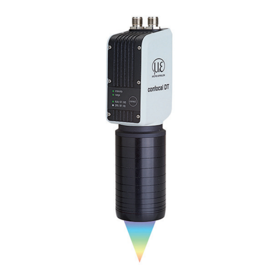
- Page 1 Quick Manual confocalDT 2410/2415 EtherCAT IFD2410-1 IFD2415-1 IFD2410-3 IFD2415-3 IFD2410-6 IFD2415-10...
-
Page 2: Table Of Contents
94496 Ortenburg / Germany Beckhoff Automation GmbH, Germany. You can find more information about the measuring system Tel. +49 (0) 8542 / 168-0 Fax +49 (0) 8542 / 168-90 in the operating instructions. They are available online at: e-mail info@micro-epsilon.com www.micro-epsilon.de/download/manuals/man-- www.micro-epsilon.com confocalDT-2410-2411-2415--en.pdf... -
Page 3: General
General General Symbols Used The following symbols are used in this document: Indicates a hazardous situation which, if not avoided, may result in minor or moderate injury. Indicates a situation that may result in property damage if not avoided. Indicates a user action. Indicates a tip for users. -
Page 4: Intended Use
General Intended Use - The measuring system is designed for use in an industrial environment. It is used for ƒ displacement, distance, movement and thickness measurement, ƒ measuring the position of parts or machine components - The measuring system must only be operated within the limits specified in the technical data. The measuring system must only be used in such a way that no persons are endangered or machines are dam- aged in the event of malfunction or total failure of the sensor. -
Page 5: Mechanical Fastening
Circumferential clamping with MA240x mounting ring, consisting of mounting block and mounting ring MA2400-27 ø27 ø46 19.75 (.78) MA2405-34 ø34 ø50 22 (.87) Micro-Epsilon recommends circumferential clamp- MA2405-54 ø54 ø70 32 (1.26) Mounting block and MA240x mounting ring confocalDT 2410/2415 Page 5... -
Page 6: Direct Fastening
Mechanical Fastening Direct fastening 48 (1.89) Mount the sensor via three M3 screws. ±0.1 63 (2.48) ±0.1 1,0 Nm max. 8 confocal DT Screwing depth Screw Tightening torque Minimum Maximum ISO 4762 3 pc. Mounting conditions IFD2410- IFD2415- free aperture 29.5 (1.16) Dimensional drawing IFD2410 / IFD2415 Dimension in mm (inch) -
Page 7: Electrical Connections
Mechanical Fastening Electrical Connections The PC2415-1/Y cable is IF2001/USB PC2415-x/OE included in delivery. Characteristics PC2415-1/Y: - Power supply PC2415-x PC2415-1/Y - Ethernet - RS422 and synchroniza- tion or encoder RS422 / Encoder Other cables are available as Synchronization / optional accessory. PS 2020 Ref. - Page 8 Mechanical Fastening Characteristics SC2415-x/OE: - Analog output Analog output - Switching outputs Digital I/O - Encoder SC2415-x/OE The SC2415-x/OE cable is optionally Encoder available. A, B The GND connections of the switching outputs are separated from supply GND 17-pin connector sensor SC2415-x/OE by filters.
-
Page 9: Supply Voltage
Voltage supply only for measuring devices, not to be used for drives or similar sources of impulse interference at the same time. MICRO-EPSILON recommends using an optional available power supply unit PS2020 for the sensor. Only turn on the power supply after wiring has been completed. -
Page 10: Sensor Leds
Sensor LEDs Sensor LEDs Color Status Meaning flashes Dark signal acquisition in progress lights up Signal saturated Intensity Yellow lights up Signal too low intensity Green lights up Signal OK range flashes Dark signal acquisition in progress lights up No target present, outside of measuring range Range Yellow lights up... -
Page 11: Correct Button
Sensor LEDs Correct Button Correct button is assigned multiple functions. As standard, the button is assigned the dark reference function. Dark reference Starts dark referencing Function Reset the device and measurement settings to Factory setting factory settings. The selected function is indicated by the flashing/illuminated Range and Intensity LEDs. Factory Dark reference setting... -
Page 12: Initial Operation
Switch to the Ethernet setup mode. Connect the sensor, e.g. via an IF2001/ Enable the EoE in your PLC USB RS422 converter from Micro-Epsilon software. Details can be found in section Switch via USB to a PC. Virtual Ethernet Port is a between EtherCAT and Ethernet Start the sensorTOOL program. -
Page 13: Switch Between Ethercat And Ethernet Setup Mode
Initial Operation Switch between EtherCAT and Ethernet Setup Mode The sensor starts in the last stored operating mode. Factory setting is EtherCAT. Access via Ethernet is possible in the Ethernet setup mode. Press and hold the Correct button on the sensor before switching on the power supply on the sensor. Release the button again as soon as the Intensity LED flashes yellow. -
Page 14: Access Via Web Interface
Initial Operation Access via Web Interface For configuration, you can switch between the video sig- nal and a display of the measured values over time. The Start the web interface of the sensor, see section appearance of the websites depends on the functions. Initial Operation. -
Page 15: Positioning The Target
Initial Operation The vertical navigation is contextual to the selection in the horizontal navigation and contains the following functions for the Home menu: - The Search settings function permits time-saving access to functions and parameters. - Measurement configuration. Allows a selection of predefined measure- ment settings. -
Page 16: Presets, Setups, Measurement Configuration, Signal Quality
Initial Operation Presets, Setups, Measurement Configuration, Signal Quality Definition - Preset: Manufacturer-specific program with settings for frequent measurement tasks; cannot be overwritten - Setup: User-specific program with relevant settings for a measurement task - Initial setup at boot (sensor start): a favorite can be selected from the setups, which is automatically activated at sensor start. - Page 17 Initial Operation For all presets, the measurement task can be individually adapted via the Signal quality slider. Reducing the measuring rate increases the exposure time for the line and thus improves the measurement quality. Measuring rate Averaging Description 0.2 kHz Static Three predefined basic settings (Static, Balanced Moving, 128 values...
-
Page 18: Checking The Video Signal, Peak Selection
Initial Operation Checking the Video Signal, Peak Selection The video signal in the graph window displays the spectral distribution of the pixels in the receiving row. The peaks are counted starting at the start of the measuring range toward the end of the measuring range. The corresponding measured value is marked by a vertical line (peak marking). -
Page 19: Distance Measurement With Website Display
Distance Measurement with Website Display Distance Measurement with Website Display Align the sensor perpendicularly to the object to be measured. Then, move the sensor (or the target) closer and closer to the start of the measuring range of the relevant sensor. As soon as the object is within the measuring field of the sensor, the sensor’s Range LED lights up (green or yellow). - Page 20 Distance Measurement with Website Display 1 Stop pauses the chart; you can still use the data selection and zoom functions. Save opens a Windows selection dialog for the file name and storage location to save the last 10,000 values in a CSV file (separation using semico- lon).
-
Page 21: One-Sided Thickness Measurement, Transparent Target
One-Sided Thickness Measurement, Transparent Target One-Sided Thickness Measurement, Trans- parent Target Preset Selection The sensor evaluates two signals reflected on the sur- faces. Based on these two signals, the sensor calculates Switch to the Home menu. the distances from the surfaces and, from this, derives Select One-sided thickness measurement in the thickness. -
Page 22: Video Signal
One-Sided Thickness Measurement, Transparent Target Video Signal If a surface of the target lies outside the measuring range, the sensor will send only one signal for the displacement, intensity and center of gravity. This may also occur if a signal is below the detection threshold. Two boundary surfaces are active when the correct thickness of a transparent material is measured. -
Page 23: Measurement Chart For Thickness Measurement
One-Sided Thickness Measurement, Transparent Target Measurement Chart for Thickness Measurement Switch to the Measurement chart tab and select Mess as the chart type. The web page shows the two distances and the thickness Ch01Thick12 (difference between 01DIST2 and 01DIST1) graphically and numerically. Optionally, the intensities of both peaks (Peak 1 = near, Peak 2 = far) can also be displayed. -
Page 24: Switch Between Ethernet Setup Mode And Ethercat
Switch between Ethernet Setup Mode and EtherCAT Switch between Ethernet Setup Mode and EtherCAT The sensors start in the last stored operating mode. With the Correct button, you can set the sensor to the EtherCAT operating mode. Press and hold the Correct button on the sensor before switching on the power supply on the sensor. Release the button again as soon as the Intensity LED flashes yellow. -
Page 25: Ethercat
EtherCAT EtherCAT Preliminary Remarks The sensor starts with the last stored operating mode. Standard is EtherCAT. You can program the sensor via SDOs. In Ethernet setup mode or with active EoE, programming is alternatively possible via Telnet or the web interface, see the sections Initial Operation, Distance Measurement and One-sided thickness measurement. -
Page 26: Saving The Settings, Continuing Ethercat Mode
EtherCAT Saving the Settings, Continuing EtherCAT Mode Programming via SDOs Programmierung über Webinterface Ethernet-Setup-Mode Ethernet over EtherCAT (EoE) Changes to the device settings: - Programming via web interface or on com- - Programming via web inter- mand level e.g. with Telnet face or on command level e.g. -
Page 27: Service, Repair
MICRO-EPSILON or to your distribu- tor/retailer. MICRO-EPSILON undertakes no liability whatsoever for damage, loss or costs caused by or related in any way to the product, in particular consequential damage, e.g., due to... -
Page 28: Decommissioning, Disposal
- A list of national laws and contacts in the EU member states can be found at https://ec.europa.eu/environment/topics/waste-and-recycling/waste-electrical-and-electronic-equipment-weee_en. Here you can inform yourself about the respective national collection and return points. - Old devices can also be returned for disposal to MICRO-EPSILON at the address given in the imprint at https://www. micro-epsilon.de/impressum/.
Need help?
Do you have a question about the confocalDT 2410 EtherCAT and is the answer not in the manual?
Questions and answers