Sign In
Upload
Manuals
Brands
Maretron Manuals
Controller
MPOWER CLMD16
Maretron MPOWER CLMD16 Load Controller Manuals
Manuals and User Guides for Maretron MPOWER CLMD16 Load Controller. We have
4
Maretron MPOWER CLMD16 Load Controller manuals available for free PDF download: User Manual, Configuration Manual, Quick Start Manual
Maretron MPOWER CLMD16 User Manual (85 pages)
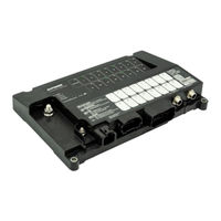
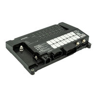
16Channel DC Load Controller Module
Brand:
Maretron
| Category:
Controller
| Size: 3 MB
Table of Contents
Table of Contents
2
Introduction
7
Clmd16 Features
8
Theory of Operation
9
Clmd 16 Hardware Description
10
Installation
11
Unpacking the Box
11
Choosing a Mounting Location
11
Mounting the Clmd16
11
Connecting the Clmd16
11
Main DC (+) Connection
13
Main DC (-) Connection
15
Iring J1 - J3 Connectors
16
Wiring a Harness Directly to J1-J3
16
Connecting J1-J3 Using Maretron Accessory Cable Assemblies
18
"J1" (25 Amp Breaker) Position Description
19
"J2" (12 Amp Breaker) Position Description
19
"J3" (General Purpose / Analog) Position Description
20
Checking Connections
20
Nmea 2000® Connections
21
Breaker (Output) Features
22
Soft Start
22
Pulse Width Modulation (Pwm)
22
Paralleling Breakers
23
Half Bridge Operation
24
Full Bridge Operation
24
Load Shedding
26
Overcurrent Protection
27
Binary Event Monitor
28
Switching Application
30
Counters
30
Timer Delay
32
Flash
32
Latches
33
Set/Reset Latch
34
Toggle
34
Toggle Latch
35
Logic
35
Alarm Output
36
Available Signals
37
Configuring the Clmd16
37
General Tab
38
Label
38
Instance
38
Breaker #(N)
39
Label
39
State
39
Default State
39
Default Lock State
39
Type
39
Current Rating
40
Instantaneous Pickup
40
Short Time Pickup
40
Input Signal
40
PWM Counter
40
Long Time Delay
40
Voltage
40
Current
41
Status
41
Tripped
41
Thermal Protection
41
Load Shed
41
Hardware Fault
41
Short to Ground
41
Short to Battery
41
Over Current
41
Open Circuit
42
Breaker Locked
42
Control Tab
43
Alarm Tab
44
Alarm Enable Signal
44
Advanced Tab
45
Device Instance
46
Location Address
46
Model Version
47
Temperatures
47
Temp 12A Groups 1 to 3
47
Temp 25A Group
47
Temp MCU
47
Supply Voltage
47
Input Supply
47
Over Voltage Fault
47
Under Voltage Fault
47
Execution Time Metrics
47
Unit Status
48
Over Current Fault
48
Runtime Metrics
48
Run Time
48
Commissioned Time
48
Counter Tab
49
Increment Signal
49
Decrement Signal
50
Reset Signal
50
Counter Type
50
Min Set Point
51
Max Set Point
51
Press Step Size
51
Hold Step Size
51
Hold Step Time
51
Hold Period
51
Active Threshold
51
Flash Tab
52
On Period
52
Off Period
52
Number of Cycles
53
Enable Signal
53
Grouping Tab
54
Groups 1 through 4
54
Group 1
54
Group 2
55
Group 3
55
Group 4
55
Inputs Tab
56
Input # (N)
57
Label
57
On Level(S)
58
Analog Reference
58
State
58
Voltage/Resistance/Current
58
High Threshold
58
High Hysteresis
58
Low Threshold
59
Low Hysteresis
59
Tanks Tab
59
Enable
60
Label
60
Pressure
60
Tank Capacity
60
Tank Number
60
Tank Type
60
Data Damping Period
61
Realtime Resistance
61
Realtime Current
61
Tank Levels Calibration
61
Manual Table
61
Fluid Density
62
Number of Table Entries
62
Current Tank Calibration
62
Step Fill Table
63
Latch Tab
65
Set Signal
65
Reset Signal
65
Load Shedding Tab
66
Channel (X) Priority
66
Medium Priority Deactivate Loads below
67
Medium Priority Activate Loads above
67
Low Priority Deactivate Loads below
67
Low Priority Active Loads above
67
Voltages above Must Follow These Rules
67
Logic Tab
68
Input a
69
Input B
69
Input C
69
Lookup Table
69
Timer Tab
70
Delay Signal
70
Delay Type
71
Delay Time
71
Toggle Tab
72
Toggle Signal
72
Discrete I/O Tab
73
Data Instance
73
Indicator
74
Installation Description Tab
74
Operating the Clmd16
75
Led Indicators
75
Diag
75
Can-A
75
Can-B
75
Power
75
Breaker Status Led Indicators
76
Override Switches
76
Maintenance
76
Troubleshooting
77
Technical Specifications
78
Certifications
78
Nmea 2000 ® Parameter Group Numbers (Pgn S )
78
Electrical
79
Mechanical
79
Environmental
80
Environmental Testing
80
Technical Support
81
Maretron (2 Year) Limited Warranty
81
Warranty Return Procedure
82
Appendix A - NMEA 2000 Interfacing
83
Clmd16 Nmea 2000 ® Periodic Data Transmitted Pgn S
83
PGN 127500 - Load Controller Connection State/Control
83
Pgn 127501 - Binary Status Report
83
Pgn 130314 - Actual Pressure
84
Pgn 127505 - Fluid Level
84
PGN 127751 - DC Voltage/Current
85
Advertisement
Maretron MPOWER CLMD16 User Manual (90 pages)
16 Channel DC Load Controller Module
Brand:
Maretron
| Category:
Control Unit
| Size: 4 MB
Table of Contents
Table of Contents
2
Introduction
6
Firmware Revision
6
CLMD16 Features
7
Theory of Operation
8
CLMD16 Hardware Description
9
Figure 1 - Hardware Description Front View
9
Figure 2 - Hardware Description Bottom View
9
Installation
10
Unpacking the Box
10
Choosing a Mounting Location
10
Mounting the CLMD16
10
Connecting the CLMD16
10
Main DC (+) Connection
11
Figure 3 - Required Connections
11
Main DC (-) Connection
13
Wiring J1 - J3 Connectors
13
Figure 4 - Required Deutsch Wire Crimping Tools
15
Figure 5 - Accessory Cable Assemblies
17
Figure 6 - Recommended Cable Assembly Connection Example
18
Checking Connections
20
NMEA 2000 Connections
21
Labeling CLMD16
21
Figure 7 - NMEA 2000 Connectors
21
Figure 8 - Populating Label Contents
22
Breaker (Output) Features
23
Overcurrent Protection
23
Figure 9 - Preparing Label Template
23
Figure 10 - Current Vs Time Graph
24
Soft Start
25
Pulse Width Modulation (PWM)
25
Figure 11 - Soft Start Voltage Ramp
25
Soft Turn on / off
26
Paralleling Breakers
26
Full Bridge Operation
27
Figure 12 - Paralleled Breakers Connection Recommendation
27
Figure 13 - Full Bridge Operation Concept
28
Load Shedding
29
Input Monitor
30
High, Low and Float Thresholds
30
Input Hysteresis
30
Figure 14 - Input Monitor Hysteresis
31
Reference Ground
32
Input Voltage Broadcast
32
Switching Application
32
Counters
32
Timer
34
Flash
34
Latch
35
Toggle
36
Logic
37
Alarm Output
38
Group Switching
38
Available Signals
39
Configuring the CLMD16
39
General Tab
40
Figure 15 - General Configuration Tab Dialog Box
40
Control Tab
45
Figure 16 - Control Tab Dialog Box
45
Alarm Tab
46
Figure 17 - Alarm Configuration Tab Dialog Box
46
Advanced Tab
47
Figure 18 - Advanced Configuration Tab (Upper Portion) Dialog Box
47
Figure 19 - Advanced Configuration Tab (Lower Portion) Dialog Box
48
Counter Tab
51
Figure 20 - Counter Configuration Tab Dialog Box
51
Flash Tab
54
Figure 21 - Flash Configuration Tab Dialog Box
54
Grouping Tab
55
Figure 22 - Grouping Configuration Tab Dialog Box
55
Inputs Tab
57
Figure 23 - Inputs Configuration Tab Dialog Box
57
Figure 24 - Inputs Configuration Tab (Resistive Input and Current Loop Channels Dialog Box)
58
Tanks Tab
60
Figure 25 - Tanks Configuration Tab Dialog Box
60
Tank Levels Calibration
62
Figure 26 - Current Loop Manual Table Calibration Tank, Initial Window Dialog Box
63
Figure 27 - Current Loop Step Fill Calibration Tank, Initial Window Dialog Box
64
Figure 28 - Current Loop Step Fill Tank Calibration Dialog Box
65
Figure 29 - Current Loop Tank Fill Confirmation Dialog Box
65
Latch Tab
66
Figure 30 - Latch Configuration Tab Dialog Box
66
Load Shedding Tab
67
Figure 31 - Load Shedding Configuration Tab Dialog Box
68
Logic Tab
69
Figure 32- Logic Confirmation Tab Dialog Box
70
Timer Tab
71
Figure 33 - Timer Configuration Tab Dialog Box
71
Toggle Tab
73
Figure 34 - Toggle Configuration Tab Dialog Box
73
Discrete I/O Tab
74
Figure 35 - Discrete I/O Configuration Tab Dialog Box
74
Group Switching Tab
75
Figure 36 - Group Switching Dialog Box
75
Installation Description Tab
76
Figure 37 - Installation Description Tab Dialog Box
77
Operating the CLMD16
78
LED Indicators
78
Diag
78
Can-A
78
Can-B
78
Power
78
Breaker Status LED Indicators
79
Override Switches
79
Maintenance
80
Troubleshooting
80
Technical Specifications
81
Certifications
81
NMEA 2000 Parameter Group Numbers
82
Electrical
83
Mechanical
83
Environmental
84
Environmental Testing
84
Technical Support
84
Maretron (2 Year) Limited Warranty
85
Warranty Return Procedure
86
Appendix A - NMEA 2000 Interfacing
87
Maretron MPOWER CLMD16 Configuration Manual (58 pages)
16 Channel DC Load Controller Module
Brand:
Maretron
| Category:
Controller
| Size: 2 MB
Table of Contents
Table of Contents
2
Requirements
5
Configuration Tools
5
CLMD16 Software Update
5
Configuration Concept
6
Understanding "Toggle" & "Momentary" Input Types
7
Switching Application Elements Definition
7
Input Signal Selection
9
Counter Element
10
Flash Element
10
Latch Element
11
Logic Element
11
Timer Element
12
Toggle Element
12
Toggle Mode" and "Manual Mode
13
Toggle Mode
13
Manual Mode
13
Configuring Hardwired Input Channels
14
Configuring Discrete I/O Input Channels
16
Configurating Output Channels
17
Configurating Tank Level Inputs
18
Configuration of Common Circuit Types
19
Applying a Physical Momentary or Sustained Contact Input Signal to Switch a Load
19
Momentary Operation of a Load from Multiple Input Sources
20
Toggle a Load on / off from Multiple Momentary Input Sources
21
Toggle a Load on / off from Multiple Momentary Input Sources Plus a "Toggle Network Input
23
Navigation / Anchor Lights Toggle Logic Using Two Momentary Input Signals
25
Navigation / Steaming / Anchor Lights Toggle Logic Using Two Momentary Input Signals
28
Polarity Reversing (H-Bridge) or Motor Direction Control Circuit
31
Turning on Two Circuits with One Switch
32
Automatic Periodic Load Turn on
33
Turning on or off a Circuit Based on Fluid Level
35
Timed Delay Circuit Upon Input Detection
38
Load Timer Sequencing
40
One Button Smooth Scroll" Dimmer Circuit with One or more Momentary Input
43
Lighting Dimmer Circuit with a Momentary SPDT Switch
45
Single Input Load Control Sequence (CLMD16 Does Something Different each Time the same Button Is Pressed)
47
Speed Windshield Wiper Control
50
One Button Motor Speed Control (PWM)
54
For more Information
57
Advertisement
Maretron MPOWER CLMD16 Quick Start Manual (8 pages)
16 Channel DC Load Controller Module
Brand:
Maretron
| Category:
Controller
| Size: 2 MB
Advertisement
Related Products
Maretron MPOWER CLMD12
Maretron CLM100
Maretron MPower CLMD16-R
Maretron CKM Series
Maretron CKM12
Maretron Categories
Monitor
Gateway
Switch
Controller
Marine Equipment
More Maretron Manuals
Login
Sign In
OR
Sign in with Facebook
Sign in with Google
Upload manual
Upload from disk
Upload from URL