Maretron M-Power CLMD16 Configuration Manual
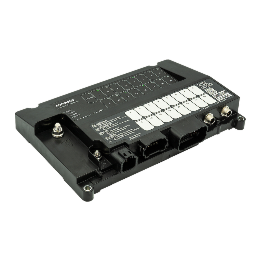
16 channel dc load controller module
Hide thumbs
Also See for M-Power CLMD16:
- Quick start manual (8 pages) ,
- User manual (85 pages) ,
- User manual (90 pages)
Table of Contents
Advertisement
Quick Links
Advertisement
Table of Contents

Subscribe to Our Youtube Channel
Related Manuals for Maretron M-Power CLMD16


Summary of Contents for Maretron M-Power CLMD16
- Page 1 ____________________________________________________________ CLMD16 16 Channel DC Load Controller Module Configuration Guide Revision 1.1 Copyright ©2020 Carling Technologies, Inc. 60 Johnson Ave. Plainville, CT 06062 USA All Rights Reserved https://www.maretron.com...
-
Page 2: Table Of Contents
____________________________________________________________ Revision History Revision Description 0.0 -0.1 Internal Review Initial Release Revised for use with CLMD16 Software Version 1.0.2.0 or above Table of Contents Requirements ................................1 Configuration Tools ............................. 1 CLMD16 Software Update ........................... 1 Configuration Concept ............................2 Switching Application Elements Definition ...................... - Page 3 ____________________________________________________________ Automatic Periodic Load Turn On ........................29 Turning On or Off a Circuit Based on Fluid Level ..................31 Timed Delay Circuit Upon Input Detection ...................... 34 Load Timer Sequencing ............................ 36 “One Button Smooth Scroll” Dimmer Circuit with One or More Momentary Input ........39 Lighting Dimmer Circuit with a Momentary SPDT Switch ................
- Page 4 This Page Intentionally Left Blank...
-
Page 5: Requirements
Configuration Tools This document outlines how to configure the CLMD16 using Maretron’s N2KAnalyzer® V3 software in conjunction with either a Maretron USB100 or a Maretron IPG100 connected to an active NMEA2000® network. For information on how to use Maretron’s N2KAnalyzer® V3 software or to download the latest version of Maretron’s N2KAnalyzer®... -
Page 6: Configuration Concept
3) NMEA 2000® 127500 Load Controller PGN messages which could come from a third party MFD (Multi-function Display) or any equipment running Maretron’s N2KView® software. The name of the channels used to receive these PGN messages are referred to as “Network Inputs 1-16”... -
Page 7: Switching Application Elements Definition
____________________________________________________________ Switching Application Elements Definition Understanding “Toggle” & “Momentary” Input Types In the following depictions you will see visual reference to what “Toggle” and “Momentary Inputs” mean to the Switching Application. It is important to understand that “Inputs” do not have to be a person pressing a switch but could be a signal becoming present. - Page 8 CLMD16 Configuration Guide___________________________________ Every time an Input becomes present or “Turns On” the Switching Application Toggle: changes state. CLMD16 Configuration Guide Rev.1.1...
-
Page 9: Input Signal Selection
____________________________________________________________ “Input Signal Selection” There is a list of input signals available to be used to activate the various “Switching Elements” these “Input Signals” consist of the following: Signal Name Description This connects the specified input to a constant Logic ‘0’ value None Selected Binary Event 1 through 12 Low The signal on binary event 1 through 12 is in the Low voltage... -
Page 10: Counter Element
CLMD16 Configuration Guide___________________________________ “Counter Element” This function is used to adjust incremental and decremental step points and gap sizes, Min. and Max set points, and user input signal delay parameters for CLMD16 output channels set to drive PWM (Pulse-Width Modulation). See following “Counter” dialog for a description of the basic “Counter”... -
Page 11: Latch Element
____________________________________________________________ “Latch Element” This function, unlike a “Toggle” signal where a single input can turn something both On and Off is exactly as it sounds, it “Latches” signals into an On state in where it requires another signal to “Unlatch” or turn Off. See following “Latch” dialog for a look at configuration input required for this feature. -
Page 12: Timer Element
CLMD16 Configuration Guide___________________________________ “Timer Element” The “Timer” element is used to delay functions for any set time up to 18 hours and 12 minutes per timer. See following “Timer” dialog for details on how to set-up a Timer Element. “Toggle Element” The “Toggle”... -
Page 13: Toggle Mode" And "Manual Mode
Mode” is not enabled and the CLMD16’s ECBs can be controlled by compatible third party MFDs and Maretron’s N2KView® software. Please note, the ECB control method from a compatible MFD will be limited to the MFD’s internal Switching Application software. The software used by third-party MFDs is usually limited to Toggle Operation whereas Maretron’s... -
Page 14: Configuring Hardwired Input Channels
CLMD16 Configuration Guide___________________________________ Configuring Hardwired Input Channels The CLMD16 has 11 hardwired input channels. Eight of these channels monitor potential connections to supply DC voltage, two monitor resistance to DC (-) and one is a current loop channel that will measure 4-20 mA DC (-) current. Each Input has “High Level” and “Low Level”... - Page 15 ____________________________________________________________ CLMD16 Configuration Guide Rev.1.1...
-
Page 16: Configuring Discrete I/O Input Channels
CLMD16 Configuration Guide___________________________________ Configuring Discrete I/O Input Channels The CLMD16 supports “Discrete I/O” inputs such as signals from Maretron’s CKM12 and VMM6 units. Configuring the CLMD16 to act upon “Discrete I/O” inputs starts first with choosing which “Discrete I/O’s” you want the CLMD16 to “watch for” or be assigned to act upon. -
Page 17: Configurating Output Channels
____________________________________________________________ Configurating Output Channels Where the CLMD16’s ECB profiles are configured, the “General Tab” should be the second if not first configuration point when configuring CLMD16 then visited again as the last stop to finalize the configuration. This method is recommended because the “General Tab” is where the ECB circuit names, and ECB “Type”... -
Page 18: Configurating Tank Level Inputs
CLMD16 Configuration Guide___________________________________ Configurating Tank Level Inputs The CLMD16 is able to broadcast up to three instances of tank level data via NMEA 2000® 127505 PGN. The following dialog(s) explain the parameters that will need to be configured for the tank level broadcast. By clicking on “Tank Levels Calibration”... -
Page 19: Configuration Of Common Circuit Types
____________________________________________________________ Configuration of Common Circuit Types Applying a Physical Momentary or Sustained Contact Input Signal to Switch a Load Applying a single momentary or sustained contact input signal to CLMD16 in order for the ECB output to replicate the input signal of “On” or “Off” is a one-step procedure. See following process to apply inputs to the CLMD16 ECBs. -
Page 20: Momentary Operation Of A Load From Multiple Input Sources
Note: a “Momentary Network Input” which could come from a third party MFD using 127500 Load Controller PGN or any equipment running Maretron’s N2KView® software could be externally applied to control the ECB directly (Shown in Red). -
Page 21: Toggle A Load On / Off From Multiple Momentary Input Sources
“Toggle Element” will be needed. Multi-Function Displays (MFDs) using 127500 Load Controller PGN or any equipment running Maretron’s N2KView® software could have direct access to the CLMD16’s ECB channels and the CLMD16 configuration will not be able to change the Digital Switching origination command for this type of equipment. - Page 22 CLMD16 Configuration Guide___________________________________ In the following circuit configuration example, there will be two momentary input sources used to switch a single CLMD16 load in a toggle fashion. One input is from a hardwired switch that has a momentary DC (-) signal called “Binary Event Low” and one input is a momentary Discrete I/O input called “Discrete I/O 1”, both will be used to toggle the single CLMD16 load.
-
Page 23: Toggle A Load On / Off From Multiple Momentary Input Sources Plus A "Toggle Network Input
MFD using 127500 Load Controller PGN or any equipment running Maretron’s N2KView® software. Because the ECB is in “Toggle Mode” the ECB’s “Input Signal” and “Toggle Network Input” will work in harmony with each other toggling the ECB On / Off. - Page 24 CLMD16 Configuration Guide___________________________________ Step 1: Assign inputs to a “Logic Element”. Where “0” is Off and “1” is On, configure the “Logic Output” in a manner to where if any input source is On, the “Logic Element’s Output” becomes active. Step 2: Place “Logic Output”...
-
Page 25: Navigation / Anchor Lights Toggle Logic Using Two Momentary Input Signals
____________________________________________________________ Navigation / Anchor Lights Toggle Logic using two Momentary Input Signals This circuit configuration type operates Navigation lights and Anchor light loads using two separate “Discrete I/O” (Momentary) inputs. One input for “Navigation Lights” and one for “Anchor Light”. When “Navigation Lights” input is commanded both “Navigation Lights” and “Anchor Light”... - Page 26 CLMD16 Configuration Guide___________________________________ Step 2: Place “Logic Output” signals into “Toggle Elements”. Step 3: Create an intervening “Logic Element” for the “Anchor Light” circuit. This “Logic Element” is used to ensure each time the “Navigation Lights” ECB (Breaker 1) is On the “Anchor Light” ECB (Breaker 2) will turn On as well.
- Page 27 ____________________________________________________________ Step 4: Place “Toggle Output” signal into “Navigation Lights” ECB and the intervening “Logic Output” signal into “Anchor Light” breaker inputs. Ensure “Toggle Mode” is Off. CLMD16 Configuration Guide Rev.1.1...
-
Page 28: Navigation / Steaming / Anchor Lights Toggle Logic Using Two Momentary Input Signals
Because a third party MFD using 127500 Load Controller PGN or any equipment running Maretron’s N2KView® software, by default, will have direct access to control the above- mentioned ECBs (#1 & 2) the “Navigation Lights Logic” circuit shown here will only operate via “Discrete I/O 1 &... - Page 29 ____________________________________________________________ Step 1: Choose appropriate output rules for the “Logic Elements”: In this example Discrete I/O 1 is “Navigation Lights” and Discrete I/O 2 is “Anchor Light”. Where 0 is Off and 1 is On, attention to the logic output correlation to the input combination (“Navigation / Anchor must be paid for proper operation.
- Page 30 CLMD16 Configuration Guide___________________________________ Step 2: Place “Logic Output” signals 1 and 3 into “Toggle Elements”. Step 3: Place “Toggle and Logic Output” signals into ECB “Input Signal” locations. Ensure “Toggle Mode” is Off. CLMD16 Configuration Guide Rev.1.1...
-
Page 31: Polarity Reversing (H-Bridge) Or Motor Direction Control Circuit
Because a third party MFD using 127500 Load Controller PGN or any equipment running Maretron’s N2KView® software, by default, will have direct access to control the above- mentioned ECBs (#1-3) the “Navigation Lights Logic” circuit shown here will only operate via “Discrete I/O 1 &... -
Page 32: Turning On Two Circuits With One Switch
CLMD16 Configuration Guide___________________________________ Turning On two Circuits with one Switch In the following example there is a single freshwater pump controlled by “Network Input” in a vessel however the end user desires to add another pump but wishes to continue to use only one switch to control both pumps. -
Page 33: Automatic Periodic Load Turn On
____________________________________________________________ Automatic Periodic Load Turn On This circuit example utilizes a “Flash Element” to operate a load called “Mast Strobe”. The following steps will outline how to configure this load to automatically turn On / Off with the frequency of On for 3 Sec. and Off for 2 Sec. triggered by a momentary input. Step 1: Assign Momentary Input to Toggle Element: In this example “Discrete I/O 8”... - Page 34 Because a third party MFD using 127500 Load Controller PGN or any equipment running Maretron’s N2KView® software, by default, will have direct access to control ECB #8 (Breaker #8), the “Flash Element” shown here will only operate via “Discrete I/O 8”. The same “Flash”...
-
Page 35: Turning On Or Off A Circuit Based On Fluid Level
____________________________________________________________ Turning On or Off a Circuit Based on Fluid Level In the following example there will be a freshwater pump load that turns Off based on tank level becoming low and restores functionality when filled back up. The freshwater pump in this example is connected to “ECB / Breaker 4”... - Page 36 CLMD16 Configuration Guide___________________________________ Step 2: Remembering our “Marker Point” of: “230 Ohms” the next step will be to navigate to the “Inputs Tab” and create a “Binary Event High Level” based on this “Marker Point”. The reason this is going to be a “High Level” indication is because the variable resistive sender Ohm level continuously goes higher as to tank level gets lower in fluid level.
- Page 37 ____________________________________________________________ Step 3: Next, an interjection of a “Logic Element” needs to be inserted into the freshwater pump circuit control. Find out what type of “Input Signal” is currently being used for the freshwater pump load. In this case it is “Network Input 4”. Remove “Network Input 4” and add an available “Logic Element”.
-
Page 38: Timed Delay Circuit Upon Input Detection
CLMD16 Configuration Guide___________________________________ Step 4: Now, Using the newly created “Binary Event High” signal, add this signal to the interjected “Logic Element” and place the original freshwater control “Input Signal” that was “Network Input 4” into the “Logic Element” as well. Select the logic element’s output parameters such that when the “Binary Event High”... - Page 39 Because a third party MFD using 127500 Load Controller PGN or any equipment running Maretron’s N2KView® software, by default, will have direct access to control ECB #4 (Breaker #4), the “Timer Element” shown here will only operate via “Discrete I/O 4”. The same “Timer”...
-
Page 40: Load Timer Sequencing
CLMD16 Configuration Guide___________________________________ Load Timer Sequencing In this example there will be a sequence of 2 timed events using “Timer Elements” to start the process of Priming, Pre-heating, and starting a Generator where these items must be handled in a manner of sequence. First sequence being to “Prime” and “Pre-Heat” and last sequence to “Start”. - Page 41 ____________________________________________________________ Step 2: Apply “Timer Outputs” to appropriate Breaker “Input Signals” for each sequence function ( Prime, Preheat, Start). Ensure “Toggle Mode” is off on each ECB. CLMD16 Configuration Guide Rev.1.1...
- Page 42 CLMD16 Configuration Guide___________________________________ CLMD16 Configuration Guide Rev.1.1...
-
Page 43: One Button Smooth Scroll" Dimmer Circuit With One Or More Momentary Input
Because a third party MFD using 127500 Load Controller PGN or any equipment running Maretron’s N2KView® software, by default, will have direct access to control all three ECBs shown in this example, the “Circuit Sequence” shown in this example will only operate via “Discrete I/O 5”. - Page 44 CLMD16 Configuration Guide___________________________________ Step 1: Apply the desired momentary inputs to control this circuit to a “Logic Element”. Where “0” is Off and “1” is On, configure the “Logic Output” in a manner to where if any input source is On the “Logic Element’s Output”...
-
Page 45: Lighting Dimmer Circuit With A Momentary Spdt Switch
____________________________________________________________ Note: The “One Button Smooth Scroll” shown in this example will only operate via “Discrete I/O 1” and “Binary event 1 Low”. When a “Counter” is selected the “One Button Smooth Scroll” behavior cannot be replicated by any equipment having direct control accessibility to the ECB via 127500 Load Controller PGN including N2KView®... - Page 46 CLMD16 Configuration Guide___________________________________ Step 1: Populate a “Logic Element” that contains both “Binary Event High” (Connected to DC+) and “Binary Event Low” (Connected to DC-) for the appropriate DC Input (In this example it is “Input 4”). Where “0” is Off and “1” is On, configure the “Logic Output” in a manner to where if any input source is On the “Logic Element’s Output”...
-
Page 47: Single Input Load Control Sequence (Clmd16 Does Something Different Each Time The Same Button Is Pressed)
____________________________________________________________ Step 3: Setup ECB parameters. Ensure “Toggle Mode” is On. Place the “Logic Output” into the “Input Signal” and be sure to select “PWM” as the ECB “Type” this will allow for the entry of the “Counter”. Note: If this circuit does not operate, please ensure parameter settings defining “Binary Event Low” and “Binary Event High”... - Page 48 CLMD16 Configuration Guide___________________________________ Step 1: Place circuit control input (Discrete I/O 1) into a “Toggle Element”, then add the output of the first “Toggle Element” into a second “Toggle Element” Step 2: Place the circuit control input into a “Latch Element”, “Set Signal”. The output of the first “Toggle Element”...
- Page 49 Because a third party MFD using 127500 Load Controller PGN or any equipment running Maretron’s N2KView® software, by default, will have direct access to control ECB #s 1 & 2 Separately (Breakers #1 & 2), the “Toggle Sequence” shown here will only operate via “Discrete I/O 1”.
-
Page 50: Speed Windshield Wiper Control
CLMD16 Configuration Guide___________________________________ 2 Speed Windshield Wiper Control In the following example there is a windshield wiper motor that accepts a DC (+) output for each speed. One for “Fast” and one for “Slow”. The windshield wiper system will need a “Park” signal (DC +) that will need to be applied when the wiper is not in “Slow”... - Page 51 ____________________________________________________________ Step 2: Place the “Logic Outputs” of the “Fast and Slow” speed ECBs into “Toggle Elements” CLMD16 Configuration Guide Rev.1.1...
- Page 52 CLMD16 Configuration Guide___________________________________ Step 3: Map the “Toggle Elements” and the single “Logic Element” into the ECBs “Input Signals”. ensure “Toggle Mode” is Off. Because damage to the motor can occur if operated incorrectly, it is best this circuit has “Manual Mode” enabled on its ECBs. This will prevent an MFD using 127500 Load Controller PGN to have direct access to control the ECBs.
- Page 53 ____________________________________________________________ Note: The same Windshield Wiper Control behavior may be able to be replicated inside the internal logic of equipment having direct control accessibility (N2KView®) or any third party MFD using 1275000 Load Controller PGN. If this logical circuit needs to be accessed by third party MFD, two combinatory “Logic Elements”...
-
Page 54: One Button Motor Speed Control (Pwm)
CLMD16 Configuration Guide___________________________________ One Button Motor Speed Control (PWM) In the following example there is a windshield wiper motor that is PWM compatible for speed control. The customer wants to have one Discrete I/O key that will turn the wiper motor On and Off and use the same key to adjust the speed at start-up. - Page 55 ____________________________________________________________ Step 2: Arrange the ECB parameters. For the ECB used as the speed control output to the motor, set the ECB to “PWM” type with the appropriate “Counter Element” assigned to the ECB. Ensure “Toggle Mode” is On for this ECB. Set the ECB parameters for the windshield wiper “Park” signal choosing an available “Logic Element”...
- Page 56 CLMD16 Configuration Guide___________________________________ Note: Because of the use of a “Counter Element” the same Windshield Wiper Control behavior will not be able to be replicated inside the internal logic of any equipment having direct control accessibility to the ECBs including N2KView® or any third party MFD using 1275000 Load Controller PGN.
-
Page 57: For More Information
____________________________________________________________ For more Information For further information about Maretron’s MPower Digital Switching solutions, please visit, https://www.maretron.com/ CLMD16 Configuration Guide Rev.1.1...
Need help?
Do you have a question about the M-Power CLMD16 and is the answer not in the manual?
Questions and answers