Sign In
Upload
Manuals
Brands
Intel Manuals
Server
MFSYS25V2
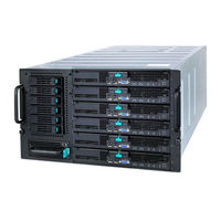
Intel MFSYS25V2 Manuals
Manuals and User Guides for Intel MFSYS25V2. We have
9
Intel MFSYS25V2 manuals available for free PDF download: Service Manual, User Manual, Specification, Tested Hardware And Operating System List, Configuration Manual
Intel MFSYS25V2 Service Manual (226 pages)
Modular Server System
Brand:
Intel
| Category:
Server
| Size: 16 MB
Table of Contents
Preface
3
About this Manual
3
Manual Organization
3
Safety Information
5
Important Safety Instructions
5
Consignes de Sécurité
5
Wichtige Sicherheitshinweise
5
Instrucciones de Seguridad Importantes
5
Warnings
6
Table of Contents
7
Modular Server System Features
17
Figure 1. Intel ® Modular Server System MFSYS25
17
Modular Server System Feature Overview
18
Figure 2. Intel ® Modular Server System MFSYS35
18
Intel® Modular Server Systems Content and References
19
Table 1. Modular Server System Features
19
Table 2. Intel ® Modular Server System MFSYS25 Contents
19
Table 3. Intel ® Modular Server System MFSYS25 Contents
20
Additional Information and Software
22
Table 4. Modular Server System References
22
Major Components
23
Front View
23
Figure 3. Front View of Intel
24
Figure 4. Front View of Intel ® Modular Server System MFSYS35
25
Rear View
27
Figure 5. Rear View of Server System
27
Front Chassis Connectors and Indicators
29
Compute Module Connectors and Indicators
30
Back Chassis Connectors and Indicators
31
Figure 8. Rear Chassis Connectors and Indicators
31
Rack Mount Options
32
Hardware Installations and Upgrades
33
Before You Begin
33
Tools and Supplies Needed
33
Chassis References
33
Installing the Intel ® Modular Server System MFSYS25/MFSYS35
33
In a Rack
33
Installation Guidelines
33
Installing Temporary Handles on System
34
Figure 9. Installing Temporary Handles
34
Mounting System in Rack
35
Hot-Swap Module Installation and Removal Guidelines
35
Replacing the Management Module
36
Removing the Management Module
36
Installing the Management Module
37
Figure 10. Removing the Management Module
37
Figure 11. Installing the Management Module
38
Installing and Removing an Ethernet Switch Module
39
Installing an Ethernet Switch Module
39
Removing an Ethernet Switch Module
40
Figure 12. Installing an Ethernet Switch Module
40
Figure 13. Removing an Ethernet Switch Module
41
Installing and Removing a Storage Control Module
42
Installing a Storage Control Module
42
Removing a Storage Control Module
43
Figure 14. Installing a Storage Control Module
43
Figure 15. Removing a Storage Control Module
44
Installing and Removing the Backup Battery
45
Installing a Backup Battery
45
Figure 16. Removing Top Cover from Storage Control Module
45
Removing a Backup Battery
46
Figure 17. Installing Backup Battery
46
Figure 18. Removing Top Cover from Storage Control Module
47
Installing and Removing a Power Supply Module
48
Figure 19. Removing Backup Battery
48
Figure 20. Removing Filler Module
49
Installing a Power Supply Module
49
Figure 21. Installing Power Supply Module
50
Removing a Power Supply Module
50
Replacing a Main Cooling Module
51
Figure 22. Removing a Power Supply Module
51
Figure 23. Removing a Main Cooling Module
52
Removing a Main Cooling Module
52
Installing a Main Cooling Module
53
Replacing the I/O Cooling Module
53
Figure 24. Installing a Main Cooling Module
53
Figure 25. Removing an I/O Cooling Module
54
Removing the I/O Cooling Module
54
Installing the I/O Cooling Module
55
Installing and Removing Hard Drives
55
Figure 26. Installing an I/O Cooling Module
55
Figure 27. Removing a 2.5-Inch Drive Carrier from a Drive Bay Module
56
Installing a 2.5-Inch Hard Drive into the Storage Bay
56
Figure 28. Installing Hard Drive into Drive Carrier
57
Figure 29. Attaching AXXTM3SATA to the Drive
58
Figure 30. Installing 2.5-Inch Drive Carrier in Drive Bay Module
59
Removing a 2.5-Inch Hard Drive from the Storage Bay
59
Figure 31. Removing a 2.5-Inch Drive Carrier from the Drive Bay Module
60
Figure 32. Removing Hard Drive from a Drive Carrier
61
Figure 33. Removing AXXTM3SATA from the Drive
62
Installing a 3.5-Inch Hard Drive into the Storage Bay
62
Figure 34. Removing a 3.5-Inch Drive Carrier from the Drive Bay Module
63
Figure 35. Installing Hard Drive into Drive Carrier
64
Figure 36. Installing 3.5-Inch Drive Carrier in Drive Bay Module
65
Removing a 3.5-Inch Hard Drive from the Storage Bay
65
Figure 37. Removing a 3.5-Inch Drive Carrier from the Drive Bay Module
66
Figure 38. Removing Hard Drive from a Drive Carrier
67
Installing and Removing an Intel® Compute Module
68
Installing an Intel® Compute Module
68
Figure 39. Installing an Intel® Compute Module
68
Removing an Intel® Compute Module
69
Figure 40. Removing an Intel® Compute Module
69
Removing and Installing the 2.5-Inch Hard Disk Drive Bay Module
70
Removing the 2.5-Inch Hard Disk Drive Bay Module
70
Installing the 2.5-Inch Hard Disk Drive Bay Module
71
Figure 41. Removing the 2.5-Inch Hard Disk Drive Bay Module
71
Figure 42. Installing the 2.5-Inch Hard Disk Drive Bay Module
72
Removing and Installing the 3.5-Inch Hard Disk Drive Bay Module
73
Removing the 3.5-Inch Hard Disk Drive Bay Module
73
Installing the 3.5-Inch Hard Disk Drive Bay Module
74
Figure 43. Removing the 3.5-Inch Hard Disk Drive Bay Module
74
Figure 44. Installing the 3.5-Inch Hard Disk Drive Bay Module
75
Replacing the Midplane
76
Removing the Midplane
76
Figure 45. Removing the Rear Module Cage
77
Figure 46. Removing the Midplane
78
Installing the Midplane
79
Figure 47. Installing the Midplane
79
Figure 48. Installing the Rear Module Cage
80
Using the Modular Server System
83
Minimum Hardware Requirements
83
Starting up Server System
83
Installing an Operating System
83
Table 5. Hardware Requirements
83
Monitoring the Server System
84
Shutting down the Server System
84
Using the Intel Modular Server Control User Interface
85
Introduction
85
System Configuration Requirements
86
Setting up a Remote Connection
87
Remote Client System Requirements
88
Modular Server Control
88
Table 6. Minimum System Requirements for Remote Web Console
88
Figure 49. Intel ® Modular Server Control Login
89
Layout and Key Navigation Features
90
Figure 50. Intel ® Modular Server Control General Layout
90
Figure 51. Intel ® Modular Server Control Configuration Screen Layout
91
Table 7. Intel ® Modular Server Control Configuration Screen Layout
92
Chassis Front
94
Figure 52. Chassis Front View
94
System
95
Intel Compute Module View
95
Figure 53. Intel ® Compute Module View
95
Table 8. Health Icons
96
Table 9. Server Action Menu
96
Table 10. Server Tabs
98
Figure 54. Server Action - Remote KVM & CD
99
Storage Configuration
100
Figure 55. Initial Storage Configuration Screen
101
Figure 56. Create Storage Pool Dialog Box
101
Figure 57. Create Storage Pool Dialog Box Example
103
Figure 58. Storage Pool Screen
104
Table 11. Health Icons
104
Table 12. Storage Pool Actions Menu
105
Table 13. Storage Pool Tabs
107
Figure 59. Create Virtual Drive Dialog Box
108
Figure 60. Virtual Drive Screen
109
Table 14. Health Icons
110
Table 15. Virtual Drive Action Menu
111
Table 16. Virtual Drive Tabs
112
Figure 61. Assign Virtual Drive
113
Figure 62. Deleted Virtual Drive
114
Figure 63. Physical Drives
115
Table 17. Health Icons
116
Table 18. Physical Drive Action Menu
117
Table 19. Physical Drive Tabs
118
Intel ® Gigabit Ethernet Switch Module 1 and 2
120
Figure 64. External Ports
120
Figure 65. Intel ® Gigabit Ethernet Switch Module View
121
Table 20. Health Icons
122
Table 21. Switch Module Action Menu
122
Table 22. Switch Module Tabs
123
Figure 66. Configure Ports Dialog Box
125
Chassis Back
126
Figure 67. Advanced Configuration Screen
126
Figure 68. Chassis Back View
127
Intel ® Storage Control Module 1 and 2
127
Figure 69. Intel ® Storage Control Module View
128
Table 23. Health Icons
129
Table 24. Status Messages
129
Table 25. Storage Control Module Action Menu
130
Intel Management Module
131
Table 26. Storage Control Module Tabs
131
Figure 70. Intel ® Management Module View
132
Table 27. Health Icons
133
Table 28. Management Module Action Menu
133
Intel Modular Server Fans and Power Supplies
134
Table 29. Management Module Tabs
134
Reports
135
Table 30. Health Icons
135
Table 31. Fans and Power Supplies Tabs
135
Storage Layout
136
Figure 71. Storage Layout Graphical View
137
Events
138
Figure 72. Storage Layout Tabular View
138
Figure 73. System Event Log Screen
139
Dashboard
140
Figure 74. Event Policy Record Window
140
Diagnostics
141
Figure 75. Dashboard View
141
Figure 76. Diagnostics
142
Figure 77. Diagnostic Tests
143
Figure 78. System Information Report Download
143
Figure 79. System Information Report
144
Settings
145
Storage Drive Caching Options
145
Figure 80. Diagnostics - Service Data
145
Storage Redundancy Check Options
146
Figure 81. Settings - Storage Caching Options Configuration
146
IP Configuration
147
Figure 82. Storage Redundancy Check Schedule
147
Figure 83. Settings - IP Configuration
148
Date and Time
149
Figure 84. Settings - System Date and Time Configuration
149
Figure 85. Calendar
150
Simple Network Management Protocol (SNMP)
151
Figure 86. SNMP Options
152
Figure 87. SNMP V3
153
Figure 88. Reset SNMP V3
154
User Accounts
155
Ldap
155
Figure 89. Settings - User Account Configuration Screen
155
Event Policies
156
Figure 90. LDAP Authentication Configuration
156
Figure 91. Settings - Event Policies Configuration Screen
157
Notification
158
Figure 92. Email Notification Configuration
158
Figure 93. SYSLOG Notification Setting
159
Import/Export
160
Language Option Setting
160
Figure 94. Configuration Import /Export
160
Feature Activation
161
Figure 95. Settings - Help Language Selection
161
Firmware Updates
162
Figure 96. Settings - Feature Activation
162
Figure 97. Settings - Firmware Update Screen
163
Restore System Settings
164
Figure 98. Settings - Restore System Settings
164
Access Online Help
166
Log out from the Intel Modular Server Control
166
Figure 99. Online Help
166
Advertisement
Intel MFSYS25V2 User Manual (212 pages)
Modular Server System
Brand:
Intel
| Category:
Server
| Size: 15.95 MB
Table of Contents
Preface
3
About this Manual
3
Manual Organization
3
Safety Information
5
Important Safety Instructions
5
Consignes de Sécurité
5
Wichtige Sicherheitshinweise
5
Instrucciones de Seguridad Importantes
5
Warnings
6
Table of Contents
7
Modular Server System Features
17
Figure 1. Intel ® Modular Server System MFSYS25
17
Modular Server System Feature Overview
18
Figure 2. Intel ® Modular Server System MFSYS35
18
Intel® Modular Server Systems Content and References
19
Table 1. Modular Server System Features
19
Table 2. Intel ® Modular Server System MFSYS25 Contents
19
Table 3. Intel ® Modular Server System MFSYS25V2 Contents
20
Table 4. Intel Modular Server System MFSYS35 Contents
21
Additional Information and Software
22
Table 5. Modular Server System References
22
Major Components
23
Front View
23
Figure 3. Front View of Intel
24
Figure 4. Front View of Intel ® Modular Server System MFSYS35
25
Rear View
27
Figure 5. Rear View of Server System
27
Front Chassis Connectors and Indicators
29
Compute Module Connectors and Indicators
30
Back Chassis Connectors and Indicators
31
Figure 8. Rear Chassis Connectors and Indicators
31
Rack Mount Options
32
Hardware Installations and Upgrades
33
Before You Begin
33
Tools and Supplies Needed
33
Chassis References
33
Installing the Intel ® Modular Server System MFSYS25/MFSYS35
33
In a Rack
33
Installation Guidelines
33
Installing Temporary Handles on System
34
Figure 9. Installing Temporary Handles
34
Mounting System in Rack
35
Hot-Swap Module Installation and Removal Guidelines
35
Replacing the Management Module
36
Removing the Management Module
36
Installing the Management Module
37
Figure 10. Removing the Management Module
37
Figure 11. Installing the Management Module
38
Installing and Removing an Ethernet Switch Module
39
Installing an Ethernet Switch Module
39
Removing an Ethernet Switch Module
40
Figure 12. Installing an Ethernet Switch Module
40
Figure 13. Removing an Ethernet Switch Module
41
Installing and Removing a Storage Control Module
42
Installing a Storage Control Module
42
Removing a Storage Control Module
43
Figure 14. Installing a Storage Control Module
43
Figure 15. Removing a Storage Control Module
44
Installing and Removing the Backup Battery
45
Installing a Backup Battery
45
Figure 16. Removing Top Cover from Storage Control Module
45
Removing a Backup Battery
46
Figure 17. Installing Backup Battery
46
Figure 18. Removing Top Cover from Storage Control Module
47
Installing and Removing a Power Supply Module
48
Figure 19. Removing Backup Battery
48
Figure 20. Removing Filler Module
49
Installing a Power Supply Module
49
Figure 21. Installing Power Supply Module
50
Removing a Power Supply Module
50
Replacing a Main Cooling Module
51
Figure 22. Removing a Power Supply Module
51
Figure 23. Removing a Main Cooling Module
52
Removing a Main Cooling Module
52
Installing a Main Cooling Module
53
Replacing the I/O Cooling Module
53
Figure 24. Installing a Main Cooling Module
53
Figure 25. Removing an I/O Cooling Module
54
Removing the I/O Cooling Module
54
Installing the I/O Cooling Module
55
Installing and Removing Hard Drives
55
Figure 26. Installing an I/O Cooling Module
55
Figure 27. Removing a 2.5-Inch Drive Carrier from a Drive Bay Module
56
Installing a 2.5-Inch Hard Drive into the Storage Bay
56
Figure 28. Installing Hard Drive into Drive Carrier
57
Figure 29. Attaching AXXTM3SATA to the Drive
58
Figure 30. Installing 2.5-Inch Drive Carrier in Drive Bay Module
59
Removing a 2.5-Inch Hard Drive from the Storage Bay
59
Figure 31. Removing a 2.5-Inch Drive Carrier from the Drive Bay Module
60
Figure 32. Removing Hard Drive from a Drive Carrier
61
Figure 33. Removing AXXTM3SATA from the Drive
62
Installing a 3.5-Inch Hard Drive into the Storage Bay
62
Figure 34. Removing a 3.5-Inch Drive Carrier from the Drive Bay Module
63
Figure 35. Installing Hard Drive into Drive Carrier
64
Figure 36. Installing 3.5-Inch Drive Carrier in Drive Bay Module
65
Removing a 3.5-Inch Hard Drive from the Storage Bay
65
Figure 37. Removing a 3.5-Inch Drive Carrier from the Drive Bay Module
66
Figure 38. Removing Hard Drive from a Drive Carrier
67
Installing and Removing an Intel® Compute Module
68
Installing an Intel® Compute Module
68
Figure 39. Installing an Intel ® Compute Module
68
Removing an Intel® Compute Module
69
Figure 40. Removing an Intel ® Compute Module
69
Using the Modular Server System
71
Minimum Hardware Requirements
71
Starting up Server System
71
Table 6. Hardware Requirements
71
Installing an Operating System
72
Monitoring the Server System
72
Shutting down the Server System
72
Using the Intel Modular Server Control User Interface
73
Introduction
73
System Configuration Requirements
74
Setting up a Remote Connection
75
Figure 41. Connection Using a Switch
75
Figure 42. Connection Using a Cross-Over Cable
75
Remote Client System Requirements
76
Modular Server Control
76
Table 7. Minimum System Requirements for Remote Web Console
76
Figure 43. Intel ® Modular Server Control Login
77
Layout and Key Navigation Features
78
Figure 44. Intel ® Modular Server Control General Layout
78
Figure 45. Intel ® Modular Server Control Configuration Screen Layout
79
Table 8. Intel ® Modular Server Control Configuration Screen Layout
80
Chassis Front
82
Figure 46. Chassis Front View
82
System
83
Intel Compute Module View
83
Figure 47. Intel ® Compute Module View
83
Table 9. Health Icons
84
Table 10. Server Action Menu
84
Table 11. Server Tabs
86
Figure 48. Server Action - Remote KVM & CD
87
Storage Configuration
88
Figure 49. Initial Storage Configuration Screen
89
Figure 50. Create Storage Pool Dialog Box
89
Figure 51. Create Storage Pool Dialog Box Example
90
Figure 52. Storage Pool Screen
91
Table 12. Health Icons
91
Table 13. Storage Pool Actions Menu
92
Table 14. Storage Pool Tabs
94
Figure 53. Create Virtual Drive Dialog Box
95
Figure 54. Virtual Drive Screen
96
Table 15. Health Icons
97
Table 16. Virtual Drive Action Menu
98
Table 17. Virtual Drive Tabs
99
Figure 55. Assign Virtual Drive
100
Figure 56. Deleted Virtual Drive
101
Figure 57. Physical Drives
102
Table 18. Health Icons
103
Table 19. Physical Drive Action Menu
104
Table 20. Physical Drive Tabs
105
Intel ® Gigabit Ethernet Switch Module 1 and 2
107
Figure 58. External Ports
107
Figure 59. Intel ® Gigabit Ethernet Switch Module View
108
Table 21. Health Icons
109
Table 22. Switch Module Action Menu
109
Table 23. Switch Module Tabs
110
Figure 60. Configure Ports Dialog Box
112
Chassis Back
113
Figure 61. Advanced Configuration Screen
113
Figure 62. Chassis Back View
114
Intel ® Storage Control Module 1 and 2
114
Figure 63. Intel ® Storage Control Module View
115
Table 24. Health Icons
116
Table 25. Status Messages
116
Table 26. Storage Control Module Action Menu
117
Intel Management Module
118
Table 27. Storage Control Module Tabs
118
Figure 64. Intel ® Management Module View
119
Table 28. Health Icons
120
Table 29. Management Module Action Menu
120
Intel Modular Server Fans and Power Supplies
121
Table 30. Management Module Tabs
121
Reports
122
Table 31. Health Icons
122
Table 32. Fans and Power Supplies Tabs
122
Storage Layout
123
Figure 65. Storage Layout Graphical View
124
Events
125
Figure 66. Storage Layout Tabular View
125
Figure 67. System Event Log Screen
126
Dashboard
127
Figure 68. Event Policy Record Window
127
Diagnostics
128
Figure 69. Dashboard View
128
Figure 70. Diagnostics
129
Figure 71. Diagnostic Tests
130
Figure 72. System Information Report Download
130
Figure 73. System Information Report
131
Settings
132
Storage Drive Caching Options
132
Figure 74. Diagnostics - Service Data
132
Figure 75. Settings - Storage Caching Options Configuration
133
Storage Redundancy Check Options
134
IP Configuration
134
Figure 76. Storage Redundancy Check Schedule
134
Figure 77. Settings - IP Configuration
135
Date and Time
136
Figure 78. Settings - System Date and Time Configuration
136
Figure 79. Calendar
137
Simple Network Management Protocol (SNMP)
138
Figure 80. SNMP Options
139
Figure 81. SNMP V3
140
Figure 82. Reset SNMP V3
141
User Accounts
142
Ldap
142
Figure 83. Settings - User Account Configuration Screen
142
Event Policies
143
Figure 84. LDAP Authentication Configuration
143
Figure 85. Settings - Event Policies Configuration Screen
144
Notification
145
Figure 86. Email Notification Configuration
145
Figure 87. SYSLOG Notification Setting
146
Import/Export
147
Language Option Setting
147
Figure 88. Configuration Import /Export
147
Feature Activation
148
Figure 89. Settings - Help Language Selection
148
Firmware Updates
149
Figure 90. Settings - Feature Activation
149
Figure 91. Settings - Firmware Update Screen
150
Restore System Settings
151
Figure 92. Settings - Restore System Settings
151
Access Online Help
153
Log out from the Intel Modular Server Control
153
Figure 93. Online Help
153
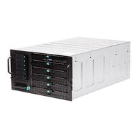
Intel MFSYS25V2 Specification (59 pages)
Modular Server System / Compute Module Specification Update
Brand:
Intel
| Category:
Server
| Size: 0.22 MB
Table of Contents
Revision History
2
Table of Contents
5
Preface
9
Product Code: MFS5000SI - Intel
10
Compute Module MFS5000SI
10
Product Code: MFS5000SIB - Intel
10
Compute Module MFS5000SI - 3 Pack
10
Product Code: MFS5520VI - Intel
10
Compute Module MFS5520VI
10
Product Code: MFS5520VIR - Intel
11
Compute Module MFS5520VIR
11
Product Code: MFS5520VIB - Intel® Compute Module MFS5520VI - 3 Pack
11
Product Code: MFSYS25 - Intel
12
Modular Server System MFSYS25
12
Product Code: MFSYS35 - Intel
12
Modular Server System MFSYS35
12
Product Code: MFSYS25V2 - Intel
12
Modular Server System MFSYS25V2
12
Product Code: AXXSCM3S - Intel
13
Storage Controller
13
Product Code: AXXSW1GB - Intel
13
Gigabit Ethernet Switch AXXSW1GB
13
Product Code: MFCMM - Intel
13
Management Module
13
Product Code: MFCMM2 - Intel
13
Management Module 2
13
Product Code: AXXPSU - 1000W Power Supply
14
Modular Server System MFSYS25
14
Product Code: Mfmidplane – Intel
14
Midplane Board
14
Modular Server System MFSYS35
14
Product Code: MFMIDPLANE2 - Intel
14
Product Code: AXXGBIOMEZ - Intel
15
Compute Module MFS5000SI - Dual
15
Gigabit Ethernet Expansion Card
15
Compute Module MFS5520VI - Dual Gigabit Ethernet Expansion Card
15
Product Code: AXXGBIOMEZV - Intel
15
Summary Tables of Changes
16
After a Hot Insertion
17
Errata
22
MFS5000SI Remote Floppy Is Not Supported
22
24X768 Resolution with Color Depth Set to Thousands of Colors Not Supported under Red Hat* Enterprise Linux 5.0 64-Bit
22
NIC Utility Dcreate.exe on MFS500SI -003 Resource CD Incomplete
23
Event Log May Report SMI Timeout Assertion after Server Power Button Is Pressed15
23
User Is Not Able to Configure Different Responses to Pressing the Server Power
23
Button in Microsoft Windows 2008* Enterprise Server Edition
23
Dual Intel® Storage Controller Configuration Not yet Supported in the Intel
24
Modular Server System MFSYS25 and MFSYS35
24
System Fault LED Does Not Come on if Smart Devices (Scms, Esms, Etc.) Are
25
Completely Non-Functional
25
Deleting Existing Assigned Virtual Drive May Result in GUI Action Failure
25
Certain Non-Critical Events Logged as Critical in GUI
25
System Fault LED Does Not Turn on for All Critical Events
26
Email Alerting Not Enabled by Default for Three Critical Events
26
Removing/Inserting USB Devices During BIOS POST or in EFI May Cause
27
Unexpected System Behavior
27
Simultaneous Remote KVM Installs of os or Applications will Not Successfully
27
Relative and Absolute KVM Mouse Mode Not Supported on All Operating Systems20
28
Compute Modules with RAID 6 Virtual Drives Experiencing Slow Response
28
CONFIRM Dialog Box Action Not Required to Complete Requested Action
29
Pressing F1 During a KVM Session will Bring up the Local KVM Console Help Not the Remote System Application Help
29
Microsoft Windows Server 2003* Cluster Support Not Available
30
Suse Enterprise Linux 10* U1 Cluster Node Shown as Running after Being
31
Physically Removed from Chassis after Failure
31
Fujitsu 146GB, 2.5" SAS Hard Drive Takes Longer than Expected to Come on Line after a Hot Insertion
31
BIOS R0048 Does Not Support Mixed Stepping E-0 and C-0 Processors
32
In Windows Enterprise Server 2008* Cluster Failover Testing, It Has Been Observed that Cluster Nodes May Lose Access to the Clustered Shared LUN Drives
32
The CMM Is Not Able to Provide Management Information for the Power Supply When an AXXPSU at Revision D73299-006 Is Installed in a System Chassis
33
The Network Time Server Setting on the Date/Time Web Page of the Intel® Modular Server Control GUI Does Not Allow Selection of Time Zones
33
Suse* Linux Enterprise Server 10 U1 will Mark the os LUN as Read Only if a SCM
34
Affinity Change Is Made While the SUSE* Linux Enterprise Server 10 Operating System Is Running or Booted
34
Chassis Fault LED Does Not Illuminate after Removing a Main Fan Module or the I/O Fan Module
34
Local Video Disappears with Console Redirection and Quiet Boot Enabled in the
35
MFS5520VI Compute Module
35
Speed Step Disable in BIOS Setup Disables the LSI SAS Controller in the
35
Red hat Enterprise Linux as 5.0 U3, 32 Bit Xen Kernel, Only Shows 13GB of
35
Memory When more than 14GB of Memory Is Installed
35
MPIO Takes a Long Time to Install under Microsoft Windows* 2003 Cluster
36
Virtual Drives from External Ports Are Not Recognized on Reboot with Microsoft
36
Windows* 2003 Enterprise
36
Extraction and Quick Reinsertion of the Intel® Server Compute Module MFS5520VI May Cause Various Issues
36
DIMM Temperature Warning in Vmware ESX 3.5 and ESX 4.0
37
MFS5000SI Compute Module Occasionally Hangs During LTO-4 Tape Backup Operations
37
Virtual Drives Within a Storage Pool May Lose Server Assignments after a Virtual Drive Has Been Deleted
37
LUN Copier Not Activated with Valid Key
38
RAID 10 to RAID 1E Automatic Migration
38
The Installation of SLES 11 X86_64 Fails on SSD
38
GMM Web GUI SSL Certification Expired on Oct 27 2009
38
The Rkvm Right Alt+F1 in Vmware 3.5 and 4.0 Launches Help Instead of ESX
39
ESM will Increase the Counter of "Received Pause Frames" When Receiving
39
Excessive SEL Logs May Report after Suse* Linux Installed
40
CPU L1 and L2 Cache Size Incorrect in MFS5520VI BIOS
40
Fail to Launch Remote KVM under Redhat Desktop WS 5.5
40
CMM Is Not Able to Control Date and Time of Ethernet Switch Module
40
Reset Ethernet Switch Module from "Advanced Configuration" will Not Generate
41
Reset" Event Log
41
Compute Module
41
The Size of Installed DIMM Is Wrong When Mirroring Mode on with MFS5000SI
42
The Rkvm Console May Report "Invalid Session Ticket" or "Authentication Failed
42
Select Rkvm Help Function by Using Hot Key Fail
42
Mixed Processors Population will Disable CPU2
43
When Virtual Drive Migration or Expansion Is Running, and HDD Physically
43
Removed, no Failure Reported
43
Lower Network Performance May be Observed When Hyper-V Role Is Added in Windows* Server 2008 R2 with more than 32GB Memory
43
Illegal FC Packets Counted as Good FC Packets in Ethernet Switch Module Interface Statistics
44
Ethernet Switch Module Jumbo Frame Changes Not Consistently Being Saved
44
Rebuild Stuck at 99% When Storage Pool Contains VD with RAID 0
45
Rkvm Mouse Not Syncing Properly with SLES 11 Enterprise 64 Bit SP1
45
MFS5520VI May Display Incorrect POST Code for Memory Error
45
HDD Cache Enable Does Not Enable HDD Cache with UFU 10.3 and 10.4
46
Mouse Acceleration with SLES 11.X over Virtual KVM
46
Clock Drift Not Saved if Selected on the Create/Modify VM Advanced Tab
47
Revertible Hot Spare Does Not Return to Being a Spare
47
Cluster Share Enabled after Chassis Is Unvirtualized and Revirtualized
47
Cluster Share Not Accessible after System Firmware Is Updated
48
Localized Help Links Take User to Welcome Page
48
Red Hat* Enterprise Linux ISO Not Visible from the VM os after Install
48
Virtual Machine KVM Only Supports US English Keyboards
49
VM Monitor Graph Returns to the Default Time Interval after a Page Auto-Refresh
49
Keys will Repeat Sometimes in Terminal Windows over Slow Networks
50
Unvirtualize Action Available When Virtualized Server Is Powered on
50
Forcing Physical Drive Online May Reset Compute Modules
50
Repair Hypervisor Install Help Information Is Incorrect
51
Prepare for Transport Action Available During Storage Pool Synchronization
51
VM Modify May Result in the VM Not Being Displayed
51
Incorrect Message Displayed When Mouse Hovers over Upper Left Corner of the VM
52
Pool
52
Disk Traffic will Not be Displayed on VM Monitor Tab Graph for New VM Sps
53
Error Message Displayed When Moving a VM
53
VM Storage Pool Available Space Is Not Correct
53
VM 'Autostart' Does Not Check Available Memory When Starting Vms
54
A Configured Revertible Hot Spare Does Not Transition Data Back to the Replacement Drive
54
Invalid Session Token During KVM Session Prevents the KVM over IP Ability for the Intel® Modular Server Systems
54
Remote KVM Mouse Mode Is Always Absolute at Launch Even When Relative Mode Is Selected
55
Remote KVM Network Connection Lost 12 Hours after Intel® Compute Module MFS5000SI Enters Standby or Sleep State
55
Microsoft Windows 2008* R2 Cluster Verification Tool Indicate Failure with SCSI Reservation
55
MAC Address Missing in SMBIOS Data for Ethernet Mezzanine Card
56
Axxgbiomezv
56
Start KVM Session Failed When Power on a VM
56
MFS5520VI Fail to Wake-Up on LAN under Microsoft* Windows Server 2003
56
CMM Unable to Send Email Alert if the Sender Address Has a Capital Letter in It
57
Advertisement
Intel MFSYS25V2 Specification (67 pages)
Technical Product Specification
Brand:
Intel
| Category:
Server
| Size: 2.05 MB
Table of Contents
Revision History
2
Table of Contents
3
1 Introduction
8
Chapter Outline
8
2 Product Overview
9
Intel Compute Module MFS2600KI Feature Set
9
Compute Module Layout
10
Connector and Component Locations
10
Figure 1. Component and Connector Location Diagram
10
External I/O Connector Locations
11
3 Functional Architecture
12
Intel ® Xeon ® Processor
12
Processor Support
12
Figure 3. Intel ® Compute Module MFS2600KI Functional Block Diagram
12
Figure 4. Processor Socket Assembly
13
Processor Initialization Error Summary
14
Table 2. Mixed Processor Configurations
15
Processor Functions Overview
16
Intel ® Quickpath Interconnect
17
Intel ® Hyper-Threading Technology
17
Processor Integrated I/O Module (IIO)
17
PCI Express Interfaces
17
DMI2 Interface to the PCH
18
Integrated IOAPIC
18
Intel ® Quickdata Technology
18
Memory Subsystem
18
Integrated Memory Controller (IMC) and Memory Subsystem
18
Figure 5. Intergrated Memory Controller (IMC) and Memory Subsystem
18
Table 4. UDIMM Support Guidelines (Preliminary. Subject to Change)
20
Table 5. RDIMM Support Guidelines (Preliminary. Subject to Change)
21
Table 6. LRDIMM Support Guidelines (Preliminary. Subject to Change)
21
Publishing Compute Module Memory
22
Memory Map and Population Rules
22
Table 7. DDR3 RDIMM Population Within a Channel
23
Table 8. DDR3L Low Voltage RDIMM Population Within a Channel
23
Table 9. DDR3 UDIMM Population Within a Channel
24
Table 10. DDR3L Low Voltage UDIMM Poplulation Within a Channel
24
Figure 2. Intel
25
Figure 6. DIMM Slot Order
25
Table 1. Intel
25
Table 3. Intel
25
Table 11. Intel Compute Module MFS2600KI DIMM Nomenclature
25
Memory RAS
26
Intel C602-J Chipset Overvew
27
Digital Media Interface (DMI)
28
PCI Express* Interface
28
Serial ATA (SATA) Controller
28
Low Pin Count (LPC) Interface
28
Serial Peripheral Interface (SPI)
28
Advanced Programmable Interrupt Controller (APIC)
28
Universal Serial Bus (USB) Controllers
29
Integrated Baseboard Management Controller Overview
29
Super I/O Controller
29
Figure 7. Integrated BMC Functional Block Diagram
29
Graphics Controller and Video Support
30
Table 12. Video Modes
30
Baseboard Management Controller
31
Table 13. Video Mode
31
Network Interface Controller (NIC)
32
Table 14. NIC LED BEHAVIOR
32
Intel Virtualization Technology for Directed I/O
33
Intel Virtualization Technology for Directed I/O (Intel VT-D)
33
4 System Security
34
BIOS Password Protection
34
Trusted Platform Module (TPM) Support
35
TPM Security BIOS
35
Physical Presence
36
TPM Security Setup Options
36
Intel Trusted Execution Technology
37
5 Connector/Header Locations and Pin-Outs
38
Board Connector Information
38
Power Connectors
38
Table 15. Board Connector Matrix
38
Table 16. Power Connector Pin-Out (J1A1)
38
I/O Connector Pin-Out Definition
39
VGA Connector
39
I/O Mezzanine Card Connector
39
Table 17. VGA Connector Pin-Out (J2K1)
39
Table 18. 120-Pin I/O Mezzanine Card Connector Pin-Out
40
Table 19. 120-Pin I/O Mezzanine Card Connector Signal Definitions
41
Midplane Signal Connector
43
Table 20. 40-Pin I/O Mezzanine Card Connector Pin-Out
43
Table 21. 96-Pin Midplane Signal Connector Pin-Out
43
Serial Port Connector
44
USB 2.0 Connectors
44
Table 22. Internal 9-Pin Serial Header Pin-Out (J4K1)
44
Low Profile Eusb SSD Support
45
Figure 8. Eusb SSD Support
45
Table 23. External USB Connector Pin-Out
45
Table 24. Pin-Out of Internal USB Connector for Low-Profile Solid State Drive (J1K1)
45
Intel MFSYS25V2 Specification (55 pages)
Technical Product Specification
Brand:
Intel
| Category:
Server
| Size: 2.64 MB
Table of Contents
Revision History
2
Table of Contents
3
1 Product Overview
8
2 System Overview
9
Introduction
9
Table 1. Server Platform Feature List
9
Figure 1. Intel Modular Server System MFSYS25 Wiring Diagram
10
Figure 2. Intel Modular Server System MFSYS35 Wiring Diagram
11
External Chassis Features - Front
12
Figure 3. Front View of Server Platform
12
Compute Module
13
I/O Cooling Module
13
Storage Enclosure
13
External Chassis Features - Rear
14
Power Supply Module
14
I/O Slots
14
Figure 4. Rear View of Server Platform
14
Chassis Management Module
15
Main Cooling Module
15
Internal Chassis Features
15
Figure 5. View of Intel Modular Server System MFSYS25 System Board Connectivity
16
Figure 6. View of Intel Modular Server System MFSYS35 System Board Connectivity
17
Midplane Board
17
Storage Interposer Board
18
Mounting and Service Features
18
Chassis
18
Rails
18
Server Management
18
Chassis Management Module
19
Compute Module Management
19
Figure 7. Server Management Connectivity
19
Reliability, Availability, Serviceability, Usability, Manageability (RASUM)
20
3 System Details
21
Specifications
21
Environmental Specifications Summary
21
Physical Specifications Summary
21
Table 2. Environmental Specifications Summary
21
Table 3. Physical Specifications of Chassis
21
Power Specifications Summary
22
Table 4. Physical Dimensions of Hardware Components
22
Table 5. Power Budget of Hardware Components
22
Table 6. Power and Heat Dissipation Specifications of Chassis
22
Chassis
23
Figure 8. Front View of Empty Intel
23
Figure 9. Front View of Empty Intel Modular Server System MFSYS35
24
Figure 10. Rear View of Empty Intel
25
Figure 11. Rear View of Empty Intel Modular Server System MFSYS35
25
Midplane Board
26
Mechanical Outline
26
Figure 12. Midplane Board Mechanical Outline (Front View)
26
Renderings
27
Figure 13. Front View of Midplane Board
27
Compute Module
28
Introduction
28
Figure 14. Rear View of Midplane Board
28
Drawings
29
Chassis Management Module
29
Introduction
29
Figure 15. Front View of Compute Module
29
Mechanical Outline
31
Figure 16. Chassis Management Module Board Outline (Top View)
31
Block Diagram
32
Figure 17. Chassis Management Module Block Diagram
32
Drawings
33
Architectural Overview
33
Figure 18. Chassis Management Module 2 Block Diagram
33
Figure 19. Front View of Chassis Management Module
33
Ethernet Switch Module
34
Introduction
34
Mechanical Outline
35
Figure 20. Ethernet Switch Module Mechanical Outline (Top View)
35
Block Diagram
36
Architectural Overview
36
Figure 21. Ethernet Switch Module Block Diagram
36
Storage Controller Module
37
Storage Subsystem Introduction
37
Mechanical Outline
37
Figure 22. Mechanical Outline of Storage Controller Module Board
37
Storage Controller Module View
38
Architectural Overview
38
Figure 23. Front View of Storage Controller Module
38
Power Supply Module
39
Jumpers and Leds
40
Intel MFSYS25V2 Specification (57 pages)
Technical Product Specification
Brand:
Intel
| Category:
Server
| Size: 2 MB
Table of Contents
Revision History
2
Table of Contents
3
1 Introduction
8
Chapter Outline
8
Intel Compute Module Use Disclaimer
8
2 Product Overview
9
Intel Compute Module MFS5520VI Feature Set
9
Table 1. Intel Compute Module MFS5520VI Feature Set
9
Compute Module Layout
10
Connector and Component Locations
10
External I/O Connector Locations
10
Figure 1. Component and Connector Location Diagram
10
Figure 2. Intel ® Compute Module MFS5520VI Front Panel Layout
11
Compute Module Mechanical Drawings
12
Figure 3. Intel Compute Module MFS5520VI - Hole and Component Positions
12
3 Functional Architecture
13
Figure 4. Intel ® Compute Module MFS5520VI Functional Block Diagram
13
Intel Xeon Processor
14
Processor Support
14
Mixed Processor Configuration
14
Table 2. Mixed Processor Configurations
15
Turbo Mode
16
Hyper-Threading
16
Intel ® Quickpath Interconnect
16
Unified Retention System Support
17
Figure 5. Unified Retention System and Unified Backplate Assembly
17
Memory Subsystem
18
Intel ® Quickpath Memory Controller
18
Publishing Compute Module Memory
18
Memory Map and Population Rules
19
Figure 6. DIMM Nomenclature
19
Figure 7. DIMM Slot Order
19
Memory RAS
20
Memory Upgrade Rules
22
Table 3. Mirroring DIMM Population Rules Variance Across Nodes
22
Intel 5520 Chipset IOH
24
Intel 82801JR I/O Controller Hub (ICH10R)
24
PCI Subsystem
25
USB 2.0 Support
25
Table 4. Intel ® Compute Module MFS5520VI PCI Bus Segment Characteristics
25
Integrated Baseboard Management Controller
26
Figure 8. Integrated BMC Hardware
27
Floppy Disk Controller
28
Keyboard and Mouse Support
28
Wake-Up Control
28
Video Support
28
Video Modes
28
Table 5. Video Modes
28
Network Interface Controller (NIC)
29
Direct Cache Access (DCA)
29
Intel Virtualization Technology for Directed I/O (Intel VT-D)
29
4 Connector/Header Locations and Pin-Outs
30
Board Connector Information
30
Power Connectors
30
Table 6. Board Connector Matrix
30
Table 7. Power Connector Pin-Out (J1A1)
30
I/O Connector Pin-Out Definition
31
VGA Connector
31
I/O Mezzanine Card Connector
31
Table 8. VGA Connector Pin-Out (J6A1)
31
Table 9. 120-Pin I/O Mezzanine Card Connector Pin-Out
32
Table 10. 120-Pin I/O Mezzanine Card Connector Signal Definitions
33
Midplane Signal Connector
35
Table 11. 40-Pin I/O Mezzanine Card Connector Pin-Out
35
Table 12. 96-Pin Midplane Signal Connector Pin-Out
35
Serial Port Connector
36
USB 2.0 Connectors
36
Table 13. Internal 9-Pin Serial Header Pin-Out (J9J1)
36
Table 14. External USB Connector Pin-Out
37
Table 15. Pin-Out of Internal USB Connector for Low-Profile Solid State Drive (J9B7)
37
Intel MFSYS25V2 Specification (50 pages)
Technical Product Specification
Brand:
Intel
| Category:
Server
| Size: 1.35 MB
Table of Contents
Revision History
2
Table of Contents
3
1 Introduction
7
Chapter Outline
7
Intel ® Compute Module Use Disclaimer
7
2 Product Overview
8
Intel Compute Module MFS5000SI Feature Set
8
Compute Module Layout
9
Connector and Component Locations
9
Figure 1. Component and Connector Location Diagram
9
External I/O Connector Locations
10
Figure 2. Intel ® Compute Module MFS5000SI Front Panel Layout
10
Compute Module Mechanical Drawings
11
Figure 3. Intel Compute Module MFS5000SI - Hole and Component Positions
11
3 Functional Architecture
12
Figure 4. Compute Module Functional Block Diagram
12
Intel 5000P Memory Controller Hub (MCH)
13
System Bus Interface
13
Processor Support
13
Memory Subsystem
14
Figure 5. CEK Processor Mounting
14
Figure 6. Memory Layout
15
Table 1. I 2 C Addresses for Memory Module SMB
15
Table 2. Maximum 8-DIMM System Memory Configuration - X8 Single Rank
16
Table 3. Maximum 8-DIMM System Memory Configuration - X4 Dual Rank
16
Figure 7. Recommended Minimum Two-DIMM Memory Configuration
18
Figure 8. Recommended Four-DIMM Configuration
19
Figure 9. Single Branch Mode Sparing DIMM Configuration
20
Intel 6321ESB I/O Controller Hub
22
PCI Subsystem
22
Table 4. PCI Bus Segment Characteristics
22
Serial ATA Support
23
Parallel ATA (PATA) Support
23
USB 2.0 Support
24
Video Support
24
Table 5. Video Modes
24
Network Interface Controller (NIC)
25
Intel I/O Acceleration Technology
25
MAC Address Definition
25
Super I/O
25
Table 6. Serial Header Pin-Out
26
4 Connector / Header Locations and Pin-Outs
27
Board Connector Information
27
Power Connectors
27
Table 7. Board Connector Matrix
27
Table 8. Power Connector Pin-Out (J1A1)
27
I/O Connector Pin-Out Definition
28
VGA Connector
28
I/O Mezzanine Card Connector
28
Table 9. VGA Connector Pin-Out (J6A1)
28
Table 10. 120-Pin I/O Mezzanine Card Connector Pin-Out
28
Midplane Signal Connector
29
Table 11. 96-Pin Midplane Signal Connector Pin-Out
29
Serial Port Connector
30
USB 2.0 Connectors
31
Table 12. Internal 9-Pin Serial 'A' Header Pin-Out (J1B1)
31
Table 13. External USB Connector Pin-Out
31
5 Jumper Block Settings
32
Recovery Jumper Blocks
32
Figure 10. Recovery Jumper Blocks
32
BMC Force Update Procedure
33
CMOS Clear and Password Reset Usage Procedure
33
Table 14. Recovery Jumpers
33
System Status LED - BMC Initialization
34
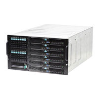
Intel MFSYS25V2 Tested Hardware And Operating System List (26 pages)
Modular server systems
Brand:
Intel
| Category:
Server
| Size: 0.52 MB
Table of Contents
Revision History
2
Table of Contents
4
1 Introduction
6
Document Organization
6
Test Overview
6
Basic Installation Testing
7
I/O Expansion Card / Peripheral Compatibility and Stress Testing
7
Pass/Fail Test Criteria
9
2 MFSYS25V2 with Intel® Virtualization Manager
10
Base System Configurations
10
Supported Guest Operating Systems & Software
10
Table 2.1 Base System Configurations Tested with Intel® Virtualization Manager Activated
10
Table 2.2 Guest Operating Systems Tested
11
Guest Operating System Storage Component Support
12
Hard Disk Drives
12
Table 2.3 Guest Operating System Storage Component Support
12
3 MFS5520VIR & MFSYS25V2 Systems
16
Base System Configurations
16
Supported Operating Systems & Software
16
Table 3.1 Base System Configurations Tested
16
Table 3.2 Operating Systems Tested for MFS5520VIR
17
Operating System Certifications
18
Table 3.3 Operating System Certifications, MFS5520VIR
18
Operating System Storage Component Support
20
Table 3.4 Operating System Certifications, MFSYS25V2 Storage
20
Table 3.5 Operating System Storage Component Support
20
I/O Expansion Cards & Peripherals
21
USB Devices
22
External Tape Drives
22
External Storage
22
Table 3.6 Intel® Compute Module MFS5520VIR Supported Items
22
Table 3.7 Intel® Modular Server System MFSYS25V2 Supported Peripherals
22
Hard Disk Drives
23
Table 3.8 Tested Hard Drives
23
Intel MFSYS25V2 Configuration Manual (15 pages)
Modular Server
Brand:
Intel
| Category:
Server
| Size: 0.54 MB
Table of Contents
Table of Contents
2
Revision History
3
Intel Modular Server
5
Mfs2600Kib
5
VM Ware V Sphere
10
Symantec Backupe
13
Advertisement
Related Products
Intel MFSYS25 - AXXPSU 1000W Power Supply Module
Intel MFSYS35
Intel Compute Module MFS2600KI
Intel MFS5520VIBR
Intel MFS5520VIR
Intel MFS2600K
Intel MFS2600KIB
Intel M70KLP Series
Intel M50FCP1UR
Intel M20MYP1UR
Intel Categories
Motherboard
Computer Hardware
Server
Server Board
Desktop
More Intel Manuals
Login
Sign In
OR
Sign in with Facebook
Sign in with Google
Upload manual
Upload from disk
Upload from URL