Intel MFSYS25V2 Specification
Technical product specification
Hide thumbs
Also See for MFSYS25V2:
- Service manual (226 pages) ,
- Specification (59 pages) ,
- Tested hardware and operating system list (26 pages)

Related Manuals for Intel MFSYS25V2


Summary of Contents for Intel MFSYS25V2
- Page 1 Intel Compute Module MFS2600KI ® Technical Product Specification Intel order number: G51989-002 Revision 1.0 June, 2012 Enterprise Platforms and Services Division...
-
Page 2: Revision History
Information in this document is provided in connection with Intel products. No license, express or implied, by ® ’s estoppel or otherwise, to any intellectual property rights is granted by this document. Except as provided in Intel ® ® Terms and Conditions of Sale for such products, Intel... -
Page 3: Table Of Contents
Super I/O Controller ..................... 22 3.6.2 Graphics Controller and Video Support ..............23 3.6.3 Baseboard Management Controller ..............24 Network Interface Controller (NIC) ............... 25 ® ® Intel Virtualization Technology for Directed I/O (Intel VT-d) ....... 26 Revision 1.0 Intel order number: G51989-002... - Page 4 Table of Contents Intel® Compute Module MFS2600KI TPS 4. System Security ........................ 27 BIOS Password Protection ................... 27 Trusted Platform Module (TPM) Support .............. 28 4.2.1 TPM security BIOS ....................28 4.2.2 Physical Presence ....................29 4.2.3 TPM Security Setup Options ................29 ®...
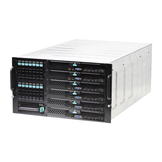
- Page 5 Figure 7. Integrated BMC Functional Block Diagram ..............22 Figure 8. eUSB SSD Support ....................38 Figure 9. Recovery Jumper Blocks .................... 39 Figure 10. POST Code Diagnostic LED Decoder ..............45 ® Figure 11. Intel Modular Server System MFSYS25V2 ............. 56 Revision 1.0 Intel order number: G51989-002...
- Page 6 List of Tables Intel® Compute Module MFS2600KI TPS List of Tables ® Table 1. Intel compute module MFS2600KI Feature Set ............2 Table 2. Mixed Processor Configurations ..................8 ® Table 3. Intel Compute Module MFS2600KI PCIe Bus Segment Characteristics ..... 11 Table 4.
- Page 7 Intel® Compute Module MFS2600KI TPS List of Tables < This page intentionally left blank.> Revision 1.0 Intel order number: G51989-002...
-
Page 8: Introduction
Intel® Compute Module MFS2600KI TPS Introduction Introduction This Technical Product Specification (TPS) provides board-specific information detailing the ® features, functionality, and high-level architecture of the Intel Compute Module MFS2600KI. Chapter Outline This document is divided into the following chapters: Chapter 1 – Introduction ... -
Page 9: Product Overview
7pin SATA connector for embedded SATA Flash Drive One eUSB for embedded USB device ® ® Intel I/O Mezzanine connectors supporting Dual Gigabit NIC Intel I/O Expansion Module (Optional) On-board Video Integrated Matrox* G200 Core, one DB15 Video port (Front) On-board Hard Drive... -
Page 10: Compute Module Layout
2.2.1 Connector and Component Locations ® The following figure shows the board layout of the Intel Compute Module MFS2600KI. Each connector and major component is identified by a number or letter. A description of each identified item is provided below the figure. -
Page 11: External I/O Connector Locations
Product Overview Intel® Compute Module MFS2600KI TPS 2.2.3 External I/O Connector Locations ® The following drawing shows the layout of the external I/O components for the Intel Compute Module MFS2600KI. USB ports 0 and 1 NIC 1 LED USB ports 2 and 3... -
Page 12: Functional Architecture
® The architecture of the Intel Compute Module MFS2600KI is developed around the integrated ® ® ® features and functions of the Intel Xeon processor E5-2600 product family the Intel C602-J ® chipset, the Intel Ethernet Controller I350 GbE controller chip and the Baseboard Management Controller. -
Page 13: Figure 4. Processor Socket Assembly
Intel does not perform validation ® testing of this configuation. For optimal performance in dual-processor configurations, Intel recommends that identical processors be installed. When using a single processor configuration, the processor must be installed into the processor socket labeled CPU1. -
Page 14: Processor Initialization Error Summary
Processor stepping within a common processor family can be mixed as long as it is listed in the processor specification updates published by Intel Corporation. 3.1.2 Processor Initialization Error Summary The following table describes mixed processor conditions and recommended actions for the ®... -
Page 15: Table 2. Mixed Processor Configurations
Does not disable the processor. Displays “0197: Processor speeds unable to synchronize” message in the Error Manager. Takes Fatal Error action (see above) and will not boot until the fault condition is remedied. Revision 1.0 Intel order number: G51989-002... -
Page 16: Processor Functions Overview
CPU, Integrated Memory Controller (IMC), and Integrated IO Module ® (IIO), have been combined into a single processor package and feature per socket; two Intel QuickPath Interconnect point-to-point links capable of up to 8.0 GT/s, up to 40 lanes of Gen 3 PCI Express* links capable of 8.0 GT/s, and 4 lanes of DMI2/PCI Express* Gen 2 interface with... -
Page 17: Intel ® Quickpath Interconnect
3.3.1 PCI Express Interfaces The integrated I/O module incorporates the PCI Express interface and supports up to 40 lanes ® of PCI Express. The following tables list the CPU PCIe port connectivity of the Intel Compute Module MFS2600KI. Revision 1.0... -
Page 18: Dmi2 Interface To The Pch
Integrated into the processor is a memory controller. Each processor provides four DDR3 channels that support the following: Unbuffered DDR3 and registered DDR3 DIMMs LR DIMM (Load Reduced DIMM) for buffered memory solutions demanding higher capacity memory subsystems Revision 1.0 Intel order number: G51989-002... - Page 19 The memory channels from processor socket 1 are identified as Channel A, B, C, and D. The memory channels from processor socket 2 are identified as Channel E, F, G, and H. Revision 1.0 Intel order number: G51989-002...
-
Page 20: Table 4. Udimm Support Guidelines (Preliminary. Subject To Change)
1333, 1600 Notes: ® Supported DRAM Densities are 1Gb, 2Gb, and 4Gb. Only 2Gb and 4Gb are validated by Intel Command Address Timing is 1N for 1DPC and 2N for 2DPC No Support for 3DPC when using UDIMMs Supported and Validated Supported but not Validate Revision 1.0... -
Page 21: Table 5. Rdimm Support Guidelines (Preliminary. Subject To Change)
1066 16GB Notes: ® Supported DRAM Densities are 1Gb, 2Gb, and 4Gb. Only 2Gb and 4Gb are validated by Intel Command Address Timing is 1N Supported and Validated Supported but not Validate Table 6. LRDIMM Support Guidelines (Preliminary. Subject to Change) -
Page 22: Publishing Compute Module Memory
3.4.3 Memory Map and Population Rules ® The following are generic DIMM population requirements that generally apply to the Intel Compute Module MFS2600KI. DIMM slots on any memory channel must be filled following the “farthest fill first” rule. -
Page 23: Table 7. Ddr3 Rdimm Population Within A Channel
DIMM 1 Number Speed 1N or 2N DIMM 2 (Blue Slot) DDR3L-1333, 1066 Empty Single-rank DDR3L-1333, 1066 Empty Dual-rank DDR3L-800 Empty Quad-rank DDR3L-1066 Single-rank Single-rank DDR3L-1066 Single-rank Dual-rank DDR3L-1066 Dual-rank Dual-rank DDR3L- 800 Single-rank Quad-rank Revision 1.0 Intel order number: G51989-002... -
Page 24: Table 9. Ddr3 Udimm Population Within A Channel
Table 10. DDR3L Low Voltage UDIMM Poplulation within a Channel Configuration DIMM 1 Number Speed 1N or 2N DIMM 2 (Blue Slot) DDR3-1333,1066 Empty Single-rank DDR3-1333, 1066 Empty Dual-rank DDR3-1066 Single-rank Single-rank DDR3-1066 Single-rank Dual-rank DDR3-1066 Dual-rank Dual-rank Revision 1.0 Intel order number: G51989-002... -
Page 25: Figure 2. Intel
Compute Module MFS2600KI TPS ® Figure 6. DIMM Slot Order 3.4.3.1 Memory Subsystem Nomenclature ® The nomenclature for DIMM sockets implemented on the Intel Compute Module MFS2600KI is detailed in the following table. ® Table 11. Intel Compute Module MFS2600KI DIMM Nomenclature... -
Page 26: Memory Ras
The spare rank must have identical or larger memory capacity than all the other ranks (sparing source ranks) on the same channel. After sparing, the sparing source rank will be lost. Revision 1.0 Intel order number: G51989-002... -
Page 27: Intel C602-J Chipset Overvew
® ® The Intel C602-J chipset in the Intel Compute Module MFS2600KI provide a connection point ® between various I/O components and Intel Xeon E5-2600 processors, which includes the following core platform functions: Digital Media Interface (DMI) PCI Express* Interface ... -
Page 28: Digital Media Interface (Dmi)
Digital Media Interface (DMI) ® Digital Media Interface (DMI) is the chip-to-chip connection between the processor and Intel C602-J chipset. This high-speed interface integrates advanced priority-based servicing allowing for concurrent traffic and true isochronous transfer capabilities. Base functionality is completely software-transparent, permitting current and legacy software to operate normally. -
Page 29: Universal Serial Bus (Usb) Controllers
USB high-speed signaling. High-speed USB 2.0 allows data transfers up ® to 480 Mb/s which is 40 times faster than full-speed USB. The Intel C602-J chipset supports up to fourteen USB 2.0 ports. All fourteen ports are high-speed, full-speed, and low-speed capable. -
Page 30: Graphics Controller And Video Support
2D modes supported for both CRT and LCD: Table 12. Video Modes 2D Mode 2D Video Mode Support 8 bpp 16 bpp 24 bpp 32 bpp 640x480 800x600 1024x768 1152x864 1280x1024 1600x1200** Revision 1.0 Intel order number: G51989-002... -
Page 31: Baseboard Management Controller
SMBus* 2.0 compliant. Parallel general-purpose I/O Ports (16 direct, 32 shared) Serial general-purpose I/O Ports (80 in and 80 out) Three UARTs Platform Environmental Control Interface (PECI) Six general-purpose timers Revision 1.0 Intel order number: G51989-002... -
Page 32: Network Interface Controller (Nic)
The default active interface is the NIC 1 port. Network Interface Controller (NIC) ® Network interface support is provided from the on-board Intel I350 NIC, which is a single, compact component with two fully integrated GbE Media Access Control (MAC) and Physical ®... -
Page 33: Intel Virtualization Technology For Directed I/O
® Intel I350 NIC will be used in conjunction with the Emulex* Pilot-III Management Controller for ® out of band Management traffic. The BMC will communicate with Intel I350 NIC over a NC-SI ® interface (RMII physical). Intel I350 NIC will be on standby power so that the BMC can send management traffic over the NC-SI interface to the network during sleep state S5. -
Page 34: System Security
In addition to restricting access to most Setup fields to viewing only when a User password is entered, defining a User password imposes restrictions on booting the system. In order to simply boot in the defined boot order, no password is required. However, the F6 Boot popup Revision 1.0 Intel order number: G51989-002... -
Page 35: Trusted Platform Module (Tpm) Support
Produces EFI and legacy interfaces to a TPM-enabled operating system for using TPM. Produces ACPI TPM device and methods to allow a TPM-enabled operating system to send TPM administrative command requests to the BIOS. Revision 1.0 Intel order number: G51989-002... -
Page 36: Physical Presence
TPM. You use this option to clear security settings for a newly initialized system or to clear a system for which the TPM ownership security key was lost. Revision 1.0 Intel order number: G51989-002... -
Page 37: Intel Trusted Execution Technology
® attacks, Intel Trusted Execution Technology integrates new security features and capabilities ® into the processor, chipset and other platform components. When used in conjunction with Intel ® Virtualization Technology, Intel Trusted Execution Technology provides hardware-rooted trust for your virtual applications. -
Page 38: Connector/Header Locations And Pin-Outs
Power Connectors The power connection is obtained using a 2x2 FCI Airmax* power connector. The following table defines the power connector pin-out. Table 16. Power Connector Pin-out (J1A1) Position Signal +12 Vdc +12 Vdc Revision 1.0 Intel order number: G51989-002... -
Page 39: I/O Connector Pin-Out Definition
The compute module provides an internal 120-pin Tyco dual-row receptacle (J1D2) and a Tyco 40-pin dual-row receptacle (J2A1) to accommodate high-speed I/O expansion modules, which expands the I/O capabilities of the compute module. The following table details the pin-out of ® the Intel I/O expansion module connector. Revision 1.0 Intel order number: G51989-002... -
Page 40: Table 18. 120-Pin I/O Mezzanine Card Connector Pin-Out
HSC2_ACT_LED HSC3_LNK_LED HSC3_ACT_LED WAKE_N Rsvd Rsvd PCIe_0_A_TXP PCIe_0_A_TXN PCIe_0_A_RXP PCIe_0_A_RXN PCIe_0_B_TXP PCIe_0_B_TXN PCIe_0_B_RXP PCIe_0_B_RXN PCIe_0_C_TXP PCIe_0_C_TXN PCIe_0_C_RXP PCIe_0_C_RXN PCIe_0_D_TXP PCIe_0_D_TXN PCIe_0_D_RXP PCIe_0_D_RXN PCIe_1_A_TXP PCIe_1_A_TXN PCIe_1_A_RXP PCIe_1_A_RXN PCIe_1_B_TXP PCIe_1_B_TXN PCIe_1_B_RXP PCIe_1_B_RXN PCIe_1_C_TXP PCIe_1_C_TXN PCIe_1_C_RXP PCIe_1_C_RXN Revision 1.0 Intel order number: G51989-002... -
Page 41: Table 19. 120-Pin I/O Mezzanine Card Connector Signal Definitions
PCIe TX- of Lane B Link 1 Host connect PCIe_1_B_RXP PCIe RX+ of Lane B Link 1 Host connect PCIe_1_B_RXN PCIe RX- of Lane B Link 1 Host connect PCIe_1_C_TXP PCIe TX+ of Lane C Link 1 Host connect Revision 1.0 Intel order number: G51989-002... - Page 42 33, 35, 38, 40, 41, 43, 46, 48, 49, 51, 54, 56, 57,59, 62, 64, 65, 67, 70, 72, 73, 75, 78, 80, 81, 83, 86, 88, 89, 91, 94, 96, 97, 99, 102, 104, 105, 107, 110 Revision 1.0 Intel order number: G51989-002...
-
Page 43: Midplane Signal Connector
Table 21. 96-pin Midplane Signal Connector Pin-out Signal Name Signal Name Signal Name XE_P1_A_RXP XE_P2_D_RXN XE_P2_D_TXP SAS_P1_TXN XE_P1_B_RXP SMB_SDA_B FM_BL_X_SP XE_P2_C_TXN XE_P1_C_RXP XE_P2_B_RXN XE_P2_B_TXP SAS_P2_TXN XE_P1_D_RXP XE_P2_A_RXN XE_P2_A_TXP Fm_bl_slot_id5 XE_P1_A_RXN SMB_SCL_A XE_P1_A_TXP XE_P2_D_TXN XE_P1_B_RXN FM_BL_SLOT_ID2 Revision 1.0 Intel order number: G51989-002... -
Page 44: Serial Port Connector
DTR (data terminal ready) SPA_RI RI (ring Indicate) Ground 5.3.5 USB 2.0 Connectors The following table details the pin-out of the external USB connectors (J1K2, J1K3) found on the front edge of the compute module. Revision 1.0 Intel order number: G51989-002... -
Page 45: Low Profile Eusb Ssd Support
Read Speed up to 35 MB/s and write Speed up to 24 MB/s. Capacity range from 256GB to 32GB. Support USB Mass Storage Class requirements for Boot capability. Figure 8. eUSB SSD Support Revision 1.0 Intel order number: G51989-002... -
Page 46: Jumper Block Settings
The compute module has several 3-pin jumper blocks that can be used to configure, protect, or recover specific features of the server board. Pin 1 on each jumper block is denoted by an “*” or “▼”. Figure 9. Recovery Jumper Blocks Revision 1.0 Intel order number: G51989-002... -
Page 47: Cmos Clear And Password Clear Usage Procedure
The CMOS Clear (J1F8) and Password Clear (J1F9) recovery features are designed such that the desired operation can be achieved with minimal system downtime. The usage procedure for ® these two features has changed from previous generation Intel server boards. The following procedure outlines the new usage model. -
Page 48: Integrated Bmc Force Update Procedure
ME not being in the proper update state, the compute module provides an Integrated BMC Force Update jumper, which forces the ME into the proper update state. The following procedure should be completed in the event the standard ME firmware update process fails. Revision 1.0 Intel order number: G51989-002... -
Page 49: Bios Recovery Jumper
3. Restore the jumper to its original position. 4. Turn on the system power. 5. Re-flash any custom blocks, such as user binary or language blocks. The system should now boot using the updated system BIOS. Revision 1.0 Intel order number: G51989-002... -
Page 50: Product Regulatory Requirements
® The Intel Compute Module MFS2600KI is evaluated as part of the Intel Modular Server System MFSYS25V2, which requires meeting all applicable system component regulatory ® requirements. Refer to the Intel Modular Server System Technical Product Specification for a complete listing of all system and component regulatory requirements. -
Page 51: Appendix A: Integration And Usage Tips
When two processors are installed, both must be of identical revision, core voltage, and bus/core speed. Mixed processor steppings are supported as long as they are listed in the processor specification updates published by Intel Corporation. However, the stepping of one processor cannot be greater than one stepping back of the other. -
Page 52: Appendix B: Post Code Diagnostic Led Decoder
Table 26. POST Progress Code LED Example Upper Nibble AMBER LEDs Lower Nibble GREEN LEDs LEDs LED #7 LED #6 LED #5 LED #4 LED #3 LED #2 LED #1 LED #0 Status Results Revision 1.0 Intel Confidential Intel order number: G51989-002... -
Page 53: Table 27. Post Progress Codes
0 DXE ACPI Init 1 DXE CSM Init 0 DXE BDS Started 1 DXE BDS connect drivers 0 DXE PCI Bus begin 1 DXE PCI Bus HPC Init 0 DXE PCI Bus enumeration Intel Confidential Revision 1.0 Intel order number: G51989-002... - Page 54 0 Recovery PEIM (Capsule loaded) POST Memory Initialization MRC Diagnostic Codes There are two types of POST Diagnostic Codes displayed by the MRC during memory initialization; Progress Codes and Fatal Error Codes. Revision 1.0 Intel Confidential Intel order number: G51989-002...
-
Page 55: Table 28. Mrc Progress Codes
1 = LED On, 0 = LED Off Upper Nibble Lower Nibble Checkpoint Description MRC Fatal Error Codes No usable memory error ® Memory is locked by Intel Trusted Execuiton Technology and is inaccessible DDR3 channel training error Intel Confidential Revision 1.0 Intel order number: G51989-002... - Page 56 Appendix B: POST Code Diagnostic LED Decoder ® Diagnostic LED Decoder 1 = LED On, 0 = LED Off Upper Nibble Lower Nibble Checkpoint Description Memory test failure DIMM configuration population error Indicates a CLTT table structure error Revision 1.0 Intel Confidential Intel order number: G51989-002...
-
Page 57: Appendix C: Post Error Code
8133 Processor 04 disabled Major 8160 Processor 01 unable to apply microcode update Major 8161 Processor 02 unable to apply microcode update Major 8162 Processor 03 unable to apply microcode update Major Intel Confidential Revision 1.0 Intel order number: G51989-002... - Page 58 Intel® Compute Module MFS2600KI TPS Appendix C: POST Error Code Error Code Error Message Response 8163 Processor 04 unable to apply microcode update Major 8170 Processor 01 failed Self Test (BIST) Major 8171 Processor 02 failed Self Test (BIST) Major...
- Page 59 DIMM_A1 encountered a Serial Presence Detection (SPD) failure Major 8561 DIMM_A2 encountered a Serial Presence Detection (SPD) failure Major 8562 DIMM_A3 encountered a Serial Presence Detection (SPD) failure Major 8563 DIMM_B1 encountered a Serial Presence Detection (SPD) failure Major Intel Confidential Revision 1.0 Intel order number: G51989-002...
- Page 60 Intel® Compute Module MFS2600KI TPS Appendix C: POST Error Code Error Code Error Message Response 8564 DIMM_B2 encountered a Serial Presence Detection (SPD) failure Major 8565 DIMM_B3 encountered a Serial Presence Detection (SPD) failure Major 8566 DIMM_C1 encountered a Serial Presence Detection (SPD) failure...
- Page 61 Minor A100 BIOS ACM Error Major A421 PCI component encountered a SERR error Fatal A5A0 PCI Express component encountered a PERR error Minor A5A1 PCI Express component encountered an SERR error Fatal Intel Confidential Revision 1.0 Intel order number: G51989-002...
-
Page 62: Table 31. Post Error Beep Codes
® not sounded continuously. Codes that are common across all Intel server boards and systems that use same generation chipset are listed in the following table. Each digit in the code is represented by a sequence of beeps whose count is equal to the digit. -
Page 63: Appendix D: Supported Intel
Compute Module MFS5520VI is supported in the following chassis: ® Intel Modular Server System MFSYS25V2 ® This section provides a high-level pictorial overview of the Intel Modular Server System ® MFSYS25V2. For more details, refer to the Intel Modular Server System Technical Product Specification (TPS). -
Page 64: Glossary
Intel® Compute Module MFS2600KI TPS Glossary Glossary This appendix contains important terms used in the preceding chapters. For ease of use, numeric entries are listed first (for example, “82460GX”) followed by alpha entries (for example, “AGP 4x”). Acronyms are followed by non-acronyms. - Page 65 Read Only Memory Real-Time Clock (Component of ICH peripheral chip on the server board) Sensor Data Record SECC Single Edge Connector Cartridge SEEPROM Serial Electrically Erasable Programmable Read-Only Memory System Event Log Server Input/Output Intel Confidential Revision 1.0 Intel order number: G51989-002...
- Page 66 Intel® Compute Module MFS2600KI TPS Glossary Term Definition SMBus* System Management Bus Server Management Interrupt (SMI is the highest priority non-maskable interrupt) Server Management Mode Server Management Software SNMP Simple Network Management Protocol To Be Determined Thermal Interface Material UART...
-
Page 67: Reference Documents
Reference Documents Intel® Compute Module MFS2600KI TPS Reference Documents ® For additional information, refer to the Intel Modular Server System Technical Product Specification. Intel Confidential Revision 1.0 Intel order number: G51989-002...
Need help?
Do you have a question about the MFSYS25V2 and is the answer not in the manual?
Questions and answers