Sign In
Upload
Manuals
Brands
Intel Manuals
Server
Compute Module MFS2600KI
User Manuals: Intel Compute Module MFS2600KI Server
Manuals and User Guides for Intel Compute Module MFS2600KI Server. We have
2
Intel Compute Module MFS2600KI Server manuals available for free PDF download: User Manual, Specification
Intel Compute Module MFS2600KI User Manual (111 pages)
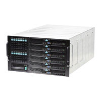
Compute Module
Brand:
Intel
| Category:
Computer Hardware
| Size: 4 MB
Table of Contents
User Guide
1
Important Safety Instructions
3
Instrucciones de Seguridad Importantes
3
Safety Information
3
Wichtige Sicherheitshinweise
3
About this Manual
5
Manual Organization
5
Preface
5
Table of Contents
6
1 Compute Module Features
12
Server System Feature Overview
12
Figure 1. Intel Compute Module MFS2600KI
12
Table 1. Compute Module Feature Summary
12
Connector and Component Locations
13
Figure 2. Component and Connector Locations
13
Configuration Jumpers
14
Figure 3. Configuration Jumper Locations
14
Table 2. Configuration Jumper Description
14
Front Panel Connectors and Indicators
15
Figure 4. Front Panel Connectors and Indicators
15
Table 3. Diagnostic LED Information
16
Hardware Requirements
17
Processor
17
Memory
17
Additional Information and Software
17
Table 4. Additional Information and Software
17
2 Hardware Installations and Upgrades
18
Before You Begin
18
Tools and Supplies Needed
18
Installation Guidelines
18
Removing and Installing an Intel Compute Module MFS2600KI
18
Removing a Compute Module from the Chassis
18
Installing a Compute Module into the Chassis
19
Removing or Installing the Top Cover
19
Removing the Top Cover
19
Installing the Top Cover
20
Removing and Installing Processor
21
Removing Processor Air Duct
21
Figure 5. Installing the Top Cover
21
Removing Processor Heatsink(S)
22
Installing the Processor
22
Figure 6. Removing Processor Heatsink
22
Figure 7. Installing Processor - Open the Socket Lever
23
Figure 8. Installing Processor - Open the Load Plate
23
Figure 9. Installing Processor - Install the Processor
23
Installing Processor Heatsink(S)
24
Figure 10. Installing Processor - Remove the Cover
24
Figure 11. Installing Processor - Close the Load Plate
24
Figure 12. Installing Processor - Latch the Locking Lever
24
Removing the Processor
25
Installing and Removing Memory
25
Removing DIMM Blank
25
Figure 13. Installing Processor Heatsink
25
Installing Memory
26
Removing Memory
26
Figure 14 Removing DIMM Blank
26
Figure 15. Installing Memory
26
Installing and Removing Mezzanine Card
27
Installing the Mezzanine Card
27
Figure 16. Removing Memory
27
Figure 17. Removing Screws from the Server Board
28
Figure 18. Installing the Standoffs for Mezzanine Card
28
Figure 19. Installing the Air Duct
29
Figure 20. Installing the Mezzanine Card
29
Removing a Mezzanine Card
30
Figure 21. Securing the Mezzanine Card
30
Figure 22. Removing a Mezzanine Card
30
Replacing the CMOS Battery
31
Figure 23. Replacing the CMOS Battery
32
3 BIOS Setup Utilities
33
Using the BIOS Setup Utility
33
Starting Setup
33
If You Cannot Access Setup
33
Setup Navigation Keyboard Commands
33
Table 5. BIOS Setup: Keyboard Command Bar
34
Setup Screen Menu Selection Bar
35
BIOS Setup Utility Screens
35
Map of Screens and Functionality
35
Table 6. Screen Map
36
Main Screen (Tab)
38
Figure 24. Main Screen
38
Advanced Screen (Tab)
41
Figure 25. Advanced Screen
41
Processor Configuration
44
Figure 26. Processor Configuration Screen
44
Figure 27. Figure and Performance Screen
53
Memory Configuration
54
Figure 28. Memory Configuration Screen
54
Memory RAS and Performance Configuration
58
Figure 29. Memory RAS and Performance Configuration Screen
58
Mass Storage Controller Configuration
61
Figure 30. Mass Storage Controller Configuration Screen
61
PCI Configuration
63
Figure 31. PCI Configuration Screen
63
NIC Configuration
64
Figure 32. NIC Configuration Screen
65
Serial Port Configuration
67
Figure 33. Serial Port Configuration Screen
67
USB Configuration
68
Figure 34. USB Configuration Screen
69
System Acoustic and Performance Configuration
71
Figure 35. System Acoustic and Performance Configuration
72
Security Screen (Tab)
73
Figure 36. Security Screen
74
Server Management Screen (Tab)
77
Figure 37. Server Management Screen
78
Console Redirection
81
Figure 38. Console Redirection Screen
82
System Information
83
Figure 39. System Information Screen
83
Boot Options Screen (Tab)
84
Figure 40. Boot Options Screen
85
CDROM Order
89
Hard Disk Order
90
Figure 41. CDROM Order Screen
90
Floppy Order
91
Figure 42. Hard Disk Order Screen
91
Figure 43. Floppy Order Screen
92
Network Device Order
93
Figure 44. Network Device Order Screen
93
Add EFI Boot Option
94
Figure 45. Add EFI Boot Option Screen
94
Delete EFI Boot Option
96
Figure 46. Delete EFI Boot Option Screen
96
Boot Manager Screen (Tab)
97
Figure 47. Boot Manager Screen
97
Error Manager Screen (Tab)
98
Figure 48. Error Manager Screen
98
Exit Screen (Tab)
100
Figure 49. Exit Screen
100
4 Troubleshooting
101
First Steps Checklist
101
Hardware Diagnostic Testing
101
Specific Problems and Corrective Actions
102
Power LED Does Not Light
102
No Video Display
102
Characters Are Distorted or Incorrect
102
No Available Storage
102
Cannot Connect to a Compute Module
103
Diagnostics Pass but Connection Fails
103
Controller Stops Working When a Mezzanine Card Is Installed
103
Mezzanine Card Stops Working Without Apparent Cause
103
Problems with Newly Installed Application Software
103
Problems with Application Software that Previously Functioned Properly
104
Devices Are Not Recognized Within the Operating System
104
Appendix A: Regulatory and Compliance Information
105
Appendix B: LED Decoder
106
Figure 50. POST Code Diagnostic LED Decoder
106
Table 7. POST Progress Code LED Example
106
Table 8. POST Progress Codes
107
Table 9. MRC Progress Codes
109
Table 10. MRC Fatal Error Codes
109
Appendix C: Getting Help
111
Warranty Information
111
Advertisement
Intel Compute Module MFS2600KI Specification (67 pages)
Technical Product Specification
Brand:
Intel
| Category:
Server
| Size: 2 MB
Table of Contents
Revision History
2
Table of Contents
3
1 Introduction
8
Chapter Outline
8
2 Product Overview
9
Intel Compute Module MFS2600KI Feature Set
9
Compute Module Layout
10
Connector and Component Locations
10
Figure 1. Component and Connector Location Diagram
10
External I/O Connector Locations
11
3 Functional Architecture
12
Intel ® Xeon ® Processor
12
Processor Support
12
Figure 3. Intel ® Compute Module MFS2600KI Functional Block Diagram
12
Figure 4. Processor Socket Assembly
13
Processor Initialization Error Summary
14
Table 2. Mixed Processor Configurations
15
Processor Functions Overview
16
Intel ® Quickpath Interconnect
17
Intel ® Hyper-Threading Technology
17
Processor Integrated I/O Module (IIO)
17
PCI Express Interfaces
17
DMI2 Interface to the PCH
18
Integrated IOAPIC
18
Intel ® Quickdata Technology
18
Memory Subsystem
18
Integrated Memory Controller (IMC) and Memory Subsystem
18
Figure 5. Intergrated Memory Controller (IMC) and Memory Subsystem
18
Table 4. UDIMM Support Guidelines (Preliminary. Subject to Change)
20
Table 5. RDIMM Support Guidelines (Preliminary. Subject to Change)
21
Table 6. LRDIMM Support Guidelines (Preliminary. Subject to Change)
21
Publishing Compute Module Memory
22
Memory Map and Population Rules
22
Table 7. DDR3 RDIMM Population Within a Channel
23
Table 8. DDR3L Low Voltage RDIMM Population Within a Channel
23
Table 9. DDR3 UDIMM Population Within a Channel
24
Table 10. DDR3L Low Voltage UDIMM Poplulation Within a Channel
24
Figure 2. Intel
25
Figure 6. DIMM Slot Order
25
Table 1. Intel
25
Table 3. Intel
25
Table 11. Intel Compute Module MFS2600KI DIMM Nomenclature
25
Memory RAS
26
Intel C602-J Chipset Overvew
27
Digital Media Interface (DMI)
28
PCI Express* Interface
28
Serial ATA (SATA) Controller
28
Low Pin Count (LPC) Interface
28
Serial Peripheral Interface (SPI)
28
Advanced Programmable Interrupt Controller (APIC)
28
Universal Serial Bus (USB) Controllers
29
Integrated Baseboard Management Controller Overview
29
Super I/O Controller
29
Figure 7. Integrated BMC Functional Block Diagram
29
Graphics Controller and Video Support
30
Table 12. Video Modes
30
Baseboard Management Controller
31
Table 13. Video Mode
31
Network Interface Controller (NIC)
32
Table 14. NIC LED BEHAVIOR
32
Intel Virtualization Technology for Directed I/O
33
Intel Virtualization Technology for Directed I/O (Intel VT-D)
33
4 System Security
34
BIOS Password Protection
34
Trusted Platform Module (TPM) Support
35
TPM Security BIOS
35
Physical Presence
36
TPM Security Setup Options
36
Intel Trusted Execution Technology
37
5 Connector/Header Locations and Pin-Outs
38
Board Connector Information
38
Power Connectors
38
Table 15. Board Connector Matrix
38
Table 16. Power Connector Pin-Out (J1A1)
38
I/O Connector Pin-Out Definition
39
VGA Connector
39
I/O Mezzanine Card Connector
39
Table 17. VGA Connector Pin-Out (J2K1)
39
Table 18. 120-Pin I/O Mezzanine Card Connector Pin-Out
40
Table 19. 120-Pin I/O Mezzanine Card Connector Signal Definitions
41
Midplane Signal Connector
43
Table 20. 40-Pin I/O Mezzanine Card Connector Pin-Out
43
Table 21. 96-Pin Midplane Signal Connector Pin-Out
43
Serial Port Connector
44
USB 2.0 Connectors
44
Table 22. Internal 9-Pin Serial Header Pin-Out (J4K1)
44
Low Profile Eusb SSD Support
45
Figure 8. Eusb SSD Support
45
Table 23. External USB Connector Pin-Out
45
Table 24. Pin-Out of Internal USB Connector for Low-Profile Solid State Drive (J1K1)
45
6 Jumper Block Settings
46
Figure 9. Recovery Jumper Blocks
46
CMOS Clear and Password Clear Usage Procedure
47
Table 25. Recovery Jumpers
47
Integrated BMC Force Update Procedure
48
Integrated BMC Initialization
48
ME Force Update Jumper
48
BIOS Recovery Jumper
49
7 Product Regulatory Requirements
50
Product Regulatory Compliance and Safety Markings
50
Product Environmental/Ecology Requirements
50
Appendix A: Integration and Usage Tips
51
Appendix B: POST Code Diagnostic LED Decoder
52
Figure 10. POST Code Diagnostic LED Decoder
52
Table 26. POST Progress Code LED Example
52
Table 27. POST Progress Codes
53
Table 28. MRC Progress Codes
55
Table 29. MRC Fatal Error Codes
55
Appendix C: POST Error Code
57
Table 30. POST Error Codes and Messages
57
Table 31. POST Error Beep Codes
62
Table 32. Integrated BMC Beep Codes
62
Appendix D: Supported Intel
63
Modular Server System
63
Figure 11. Intel Modular Server System MFSYS25V2
63
Glossary
64
Reference Documents
67
Advertisement
Related Products
Intel MFS2600K
Intel MFS2600KIB
Intel MFSYS25V2
Intel MFSYS25 - AXXPSU 1000W Power Supply Module
Intel MFSYS35
Intel MFS5520VIBR
Intel MFS5520VIR
Intel MB440LX
Intel M20MYP1UR
Intel M50CYP1UR Series
Intel Categories
Motherboard
Computer Hardware
Server
Server Board
Desktop
More Intel Manuals
Login
Sign In
OR
Sign in with Facebook
Sign in with Google
Upload manual
Upload from disk
Upload from URL