Intel MFSYS25V2 Specification
Technical product specification
Hide thumbs
Also See for MFSYS25V2:
- Service manual (226 pages) ,
- Specification (67 pages) ,
- Tested hardware and operating system list (26 pages)

Related Manuals for Intel MFSYS25V2


Summary of Contents for Intel MFSYS25V2
- Page 1 Intel Compute Module MFS5520VI ® Technical Product Specification Intel order number: E64311-007 Revision 1.5 December, 2010 Enterprise Platforms and Services Division...
-
Page 2: Revision History
Intel products are not intended for use in medical, life saving, or life sustaining applications. Intel may make changes to specifications and product descriptions at any time, without notice. -
Page 3: Table Of Contents
Network Interface Controller (NIC) ................ 22 3.7.1 Direct Cache Access (DCA) .................. 22 ® ® Intel Virtualization Technology for Directed I/O (Intel VT-d)........ 22 4. Connector/Header Locations and Pin-outs ..............23 Board Connector Information................. 23 Revision 1.5 Intel order number: E64311-007... - Page 4 Table of Contents Intel® Compute Module MFS5520VI TPS Power Connectors ....................23 I/O Connector Pin-out Definition ................24 4.3.1 VGA Connector...................... 24 4.3.2 I/O Mezzanine Card Connector ................24 4.3.3 Midplane Signal Connector..................28 4.3.4 Serial Port Connector .................... 29 4.3.5...
- Page 5 Intel® Compute Module MFS5520VI TPS List of Figures List of Figures Figure 1. Component and Connector Location Diagram .............. 3 ® Figure 2. Intel Compute Module MFS5520VI Front Panel Layout..........4 ® Figure 3. Intel Compute Module MFS5520VI – Hole and Component Positions ......5 ®...
- Page 6 List of Tables Intel® Compute Module MFS5520VI TPS List of Tables Table 1. Intel compute module MFS5520VI Feature Set .............. 2 Table 2. Mixed Processor Configurations ..................8 Table 3. Mirroring DIMM Population Rules Variance across Nodes ........... 15 ®...
- Page 7 Intel® Compute Module MFS5520VI TPS List of Tables < This page intentionally left blank.> Revision 1.5 Intel order number: E64311-007...
-
Page 8: Introduction
It is the responsibility of the system integrator who chooses not to use Intel-developed server building blocks to consult vendor datasheets and operating parameters to determine the amount of airflow required for their specific application and environmental conditions. -
Page 9: Product Overview
Compute Module MFS5520VI is a monolithic printed circuit board with features that were designed to support the high-density compute module market. Intel Compute Module MFS5520VI Feature Set ® Table 1. Intel compute module MFS5520VI Feature Set Feature Description ® ®... -
Page 10: Compute Module Layout
CPU 1 DIMM Slots Figure 1. Component and Connector Location Diagram 2.2.2 External I/O Connector Locations ® The following drawing shows the layout of the external I/O components for the Intel Compute Module MFS5520VI. Revision 1.5 Intel order number: E64311-007... -
Page 11: Figure 2. Intel ® Compute Module Mfs5520Vi Front Panel Layout
Product Overview Intel® Compute Module MFS5520VI TPS AF003120 USB ports 0 and 1 Hard Drive Activity LED USB ports 2 and 3 ID LED Video Power button I/O Mezzanine NIC ports 1 and Power and Fault LEDs 2 LEDs NIC ports 1 and 2 LEDs ®... -
Page 12: Compute Module Mechanical Drawings
Intel® Compute Module MFS5520VI TPS Product Overview 2.2.3 Compute Module Mechanical Drawings 262.89 256.54 254.58 249.42 244.42 239.84 234.26 224.10 223.39 213.94 209.52 203.78 207.65 192.99 185.99 173.99 166.99 152.27 148.40 142.11 141.77 131.95 121.79 120.65 115.85 111.63 104.50 101.47 98.85... -
Page 13: Functional Architecture
82801JR ICH10 RAID. The chipset is designed for ® ® ® systems based on the Intel Xeon Processor in FC-LGA 1366 socket B package with Intel ® QuickPath Interconnect (Intel QPI). The chipset contains two main components: ® Intel 5520 Chipset I/O Hub (IOH) that provides a connection point between various I/O components. -
Page 14: Intel Xeon Processor
Processor Population Rules Note: Although the Compute Module does support dual-processor configurations consisting of different processors that meet the defined criteria below, Intel does not perform validation testing of this configuation. For optimal performance in dual-processor configurations, Intel recommends that identical processors be installed. -
Page 15: Table 2. Mixed Processor Configurations
Logs the error. Alerts the Integrated BMC about the configuration error. Does not disable the processor. Displays “0195: Processor 0x Intel(R) QPI speed mismatch” message in the Error Manager. If POST Error Pause is disabled in the Setup, continues to boot in a degraded state. -
Page 16: Turbo Mode
QPI link consists of 20 pairs of uni-directional differential lanes for the transmitter ® and receiver, plus a differential forwarded clock. A full-width Intel QPI link pair consists of 84 signals (20 differential pairs in each direction plus a forwarded differential clock in each ®... -
Page 17: Unified Retention System Support
3.1.6 Unified Retention System Support The Compute Module complies with Intel’s Unified Retention System (URS) and the Unified Backplate Assembly. The Compute Module ships with a made-up assembly of Independent Loading Mechanism (ILM) and Unified Backplate at each processor socket. -
Page 18: Memory Subsystem
Maximum memory capacity of 192 GB with two processors installed Use of identical DIMMs in the compute module is recommended ® The following configurations are not validated or supported with the Intel Compute Module MFS5520VI: Mixing of RDIMMs and UDIMMs is not supported... -
Page 19: Memory Map And Population Rules
Functional Architecture Intel® Compute Module MFS5520VI TPS 3.2.3 Memory Map and Population Rules ® The nomenclature for DIMM sockets implemented on the Intel Compute Module MFS5520VI is detailed in the following figures. Processor Socket 1 Processor Socket 2 Channel A... -
Page 20: Memory Ras
If one socket fails the population requirements for RAS, the BIOS sets all six channels to the Channel Independent mode. ® ® ® The memory slots of DDR3 channels from the Intel Xeon Processor 5500 series and Intel ® Xeon Processor 5600 series processors should be populated on a farthest first fashion. - Page 21 Functional Architecture Intel® Compute Module MFS5520VI TPS achieved across channels. Active channels hold the primary image and the other channels hold ® the secondary image of the system memory. The integrated memory controller in the Intel ® ® ® Xeon...
-
Page 22: Memory Upgrade Rules
Current RAS mode of operation Existing DDR3 DIMM population DDR3 DIMM characteristics ® ® ® Optimization techniques used by the Intel Xeon Processor 5500 series and Intel ® Xeon Processor 5600 series to maximize memory bandwidth In the Channel Independent mode, all DDR3 channels operate independently. The Channel Independent mode can also be used to support a single DIMM configuration in channel A and in the single channel mode. - Page 23 Intel® Compute Module MFS5520VI TPS The memory operational mode is configurable at the channel level. Two modes are supported: Independent Channel and Mirrored Channel. ® ® The memory slots of each DDR3 channel from the Intel Xeon Processor 5500 series ® ®...
-
Page 24: Intel 5520 Chipset Ioh
® The Intel ® 5520 Chipset component is an I/O Hub (IOH.) The Intel ® 5520 Chipset IOH provides a connection point between various I/O components and Intel processors through ® the Intel QPI interface. The Intel ® 5520 Chipset IOH is capable of interfacing with up to 36 PCI Express* lanes, which can be configured in various combinations of x4, x8, x16, and limited x2 and x1 devices. -
Page 25: Pci Subsystem
3.4.1 PCI Subsystem ® The primary I/O buses for the Intel Compute Module MFS5520VI are PCI Express* Gen1 and PCI Express* Gen2 with six independent PCI bus segments. PCI Express* Gen1 and Gen2 are dual-simplex point-to point serial differential low-voltage interconnects. -
Page 26: Integrated Baseboard Management Controller
Intel® Compute Module MFS5520VI TPS Functional Architecture Four external connectors are located on the front of the compute module. One internal 2x5 header is provided, capable of supporting a low-profile USB solid state drive. Two ports are routed to the Integrated BMC to support rKVM. -
Page 27: Figure 8. Integrated Bmc Hardware
Functional Architecture Intel® Compute Module MFS5520VI TPS 2D Graphics Acceleration DDR2 graphics memory interface Up to 1600x1200 pixel resolution Figure 8. Integrated BMC Hardware Revision 1.5 Intel order number: E64311-007... -
Page 28: Floppy Disk Controller
Intel® Compute Module MFS5520VI TPS Functional Architecture 3.5.1 Floppy Disk Controller The Compute Module does not support a floppy disk controller interface. However, the compute module BIOS recognizes USB floppy devices. 3.5.2 Keyboard and Mouse Support The Compute Module does not support PS/2 interface keyboards and mice. However, the compute module BIOS recognizes USB specification-compliant keyboard and mice. -
Page 29: Network Interface Controller (Nic)
This is accomplished by placing the data from the I/O devices directly into the CPU cache through hints to the processor to perform ® ® a data pre-fetch and install it in its local caches. The Intel Xeon Processor 5500 series and ®... -
Page 30: Connector/Header Locations And Pin-Outs
Intel® Compute Module MFS5520VI TPS Connector/Header Locations and Pin-outs Connector/Header Locations and Pin-outs Board Connector Information The following section provides detailed information regarding all connectors, headers, and jumpers on the compute module. The following table lists all connector types available on the board and the corresponding reference designators printed on the silkscreen. -
Page 31: I/O Connector Pin-Out Definition
Connector/Header Locations and Pin-outs Intel® Compute Module MFS5520VI TPS I/O Connector Pin-out Definition 4.3.1 VGA Connector The following table details the pin-out definition of the VGA connector (J6K1). Table 8. VGA Connector Pin-out (J6A1) Signal Name Description V_IO_R_CONN Red (analog color signal R) -
Page 32: Table 9. 120-Pin I/O Mezzanine Card Connector Pin-Out
Intel® Compute Module MFS5520VI TPS Connector/Header Locations and Pin-outs Table 9. 120-pin I/O Mezzanine Card Connector Pin-out Signal Name Signal Name P3V3 P3V3 P3V3 P3V3 P3V3 P3V3 P3V3AUX P3V3AUX P3V3AUX P3V3AUX SMB_SDA SMB_SCL HSC0_LNK_LED HSC0_ACT_LED HSC1_LNK_LED HSC1_ACT_LED HSC2_LNK_LED HSC2_ACT_LED HSC3_LNK_LED... -
Page 33: Table 10. 120-Pin I/O Mezzanine Card Connector Signal Definitions
Connector/Header Locations and Pin-outs Intel® Compute Module MFS5520VI TPS Signal Name Signal Name PCIe_1_D_TXP PCIe_1_D_TXN PCIe_1_D_RXP PCIe_1_D_RXN Mezz_Present Reset_N Clk0_100M_PCIE_P Clk0_100M_PCIE_N Rsvd Rsvd Rsvd Rsvd Rsvd Rsvd Rsvd P12V P12V P12V P12V P12V P12V Table 10. 120-pin I/O Mezzanine Card Connector Signal Definitions... - Page 34 Intel® Compute Module MFS5520VI TPS Connector/Header Locations and Pin-outs Signal Name Signal Description Purpose Connector Location PCIe_1_C_TXN PCIe TX- of Lane C Link 1 Host connect PCIe_1_C_RXP PCIe RX+ of Lane C Link 1 Host connect PCIe_1_C_RXN PCIe RX- of Lane C Link 1...
-
Page 35: Midplane Signal Connector
Connector/Header Locations and Pin-outs Intel® Compute Module MFS5520VI TPS Table 11. 40-pin I/O Mezzanine Card Connector Pin-out Signal Name Connector Location Signal Name Connector Location RMII_IBMC_IOMEZZ XE_B1_TXP _CRS_DV XE_B1_TXN XE_B1_RXP XE_B1_RXN XE_B2_TXP XE_B2_TXN XE_B2_RXP XE_B2_RXN XE_D2_TXP XE_D2_TXN XE_D1_RXP XE_D1_RXN XE_D1_TXP... -
Page 36: Serial Port Connector
Intel® Compute Module MFS5520VI TPS Connector/Header Locations and Pin-outs Signal Name Signal Name Signal Name XE_P1_B_TXP 12V (BL_PWR_ON) XE_P1_C_RXN reserved XE_P1_C_TXP XE_P2_B_TXN XE_P1_D_RXN reserved XE_P1_D_TXP XE_P2_A_TXN SAS_P1_RXP SMB_SDA_A XE_P1_A_TXN FM_BL_SLOT_ID0 XE_P2_C_RXP FM_BL_SLOT_ID3 XE_P1_B_TXN FM_BL_SLOT_ID4 SAS_P2_RXP reserved XE_P1_C_TXN reserved spare reserved... -
Page 37: Table 14. External Usb Connector Pin-Out
Connector/Header Locations and Pin-outs Intel® Compute Module MFS5520VI TPS Table 14. External USB Connector Pin-out Signal Name Description USB_PWR USB_N Differential data line paired with DATAH0 USB_P (Differential data line paired with DATAL0 Ground One low-profile 2x5 connector (J9B7) on the compute module provides an option to support low- ®... -
Page 38: Jumper Block Settings
Intel® Compute Module MFS5520VI TPS Jumper Block Settings Jumper Block Settings The server board has several 3-pin jumper blocks that can be used to configure, protect, or recover specific features of the server board. Pin 1 on each jumper block is denoted by an “*”... -
Page 39: Cmos Clear And Password Clear Usage Procedure
The CMOS Clear (J9A4) and Password Clear (J9A3) recovery features are designed such that the desired operation can be achieved with minimal system downtime. The usage procedure for ® these two features has changed from previous generation Intel server boards. The following procedure outlines the new usage model. -
Page 40: Integrated Bmc Initialization
Intel® Compute Module MFS5520VI TPS Jumper Block Settings 4. Move jumper from the default operating position (pins 1-2) to the “Enabled” position (pins 2-3) 5. Close the compute module. 6. Reinstall and power up the compute module. 7. Perform Integrated BMC firmware update procedure. -
Page 41: Product Regulatory Requirements
System MFSYS25/MFSYS25V2/MFSYS35, which requires meeting all applicable system component environmental and ecology requirements. For a complete listing of all system and ® component environment and ecology requirements and markings, refer to the Intel Modular Server System Technical Product Specification. Revision 1.5... -
Page 42: Appendix A: Integration And Usage Tips
(DIMM sockets A1, B1, C1, D1, E1, and F1) performs better than a three- DIMM configuration (DIMM sockets A1, B1, and C1). For a list of Intel supported operating systems, add-in cards, and peripherals for this server board, see the Intel ®... -
Page 43: Appendix B: Integrated Bmc Sensor Tables
Appendix B: Integrated BMC Sensor Tables Intel® Compute Module MFS5520VI TPS Appendix B: Integrated BMC Sensor Tables This appendix lists the sensor identification numbers and information regarding the sensor type, name, supported thresholds, and a brief description of the sensor purpose. See the Intelligent Platform Management Interface Specification, Version 2.0, for sensor and event/reading-type... -
Page 44: Table 17. Mfs5520Vi Sensors
Intel® Compute Module MFS5520VI TPS Appendix B: Integrated BMC Sensor Tables Fault LED This column indicates whether an assertion of an event lights the front panel fault LED. The Integrated BMC aggregates all fault sources (including outside sources such as the BIOS) such that the LED will be lit as long as any source indicates that a fault state exists. - Page 45 Appendix B: Integrated BMC Sensor Tables Intel® Compute Module MFS5520VI TPS Sensor Name Sensor # Sensor Type Event/Reading Event Offset Contrib. To Rearm Stand-by Type Triggers System Status 08 - Timer interrupt Physical Sensor 04 - LAN leash Security Specific...
- Page 46 Intel® Compute Module MFS5520VI TPS Appendix B: Integrated BMC Sensor Tables Sensor Name Sensor # Sensor Type Event/Reading Event Offset Contrib. To Rearm Stand-by Type Triggers System Status nc = Voltage Threshold Degraded BB +5.0V STBY [u, l] [c, nc]...
- Page 47 Appendix B: Integrated BMC Sensor Tables Intel® Compute Module MFS5520VI TPS Sensor Name Sensor # Sensor Type Event/Reading Event Offset Contrib. To Rearm Stand-by Type Triggers System Status Digital Processor 01 – State Discrete CPU Missing Non-fatal – Asserted Digital Temperature 01 –...
- Page 48 Intel® Compute Module MFS5520VI TPS Appendix B: Integrated BMC Sensor Tables Sensor Name Sensor # Sensor Type Event/Reading Event Offset Contrib. To Rearm Stand-by Type Triggers System Status 1: Device Present Sensor Drive Slot C3h, Specific Drive 1,2 None Threshold...
-
Page 49: Appendix C: Post Error Messages And Handling
Processor 0x cache size mismatch detected. Fatal 0193 Processor 0x stepping mismatch. Minor 0194 Processor 0x family mismatch detected. Fatal 0195 Processor 0x Intel(R) QPI speed mismatch. Major 0196 Processor 0x model mismatch. Fatal 0197 Processor 0x speeds mismatched. Fatal 0198 Processor 0x family is not supported. - Page 50 Intel® Compute Module MFS5520VI TPS Appendix C: POST Error Messages and Handling Error Code Error Message Response 8160 Processor 01 unable to apply microcode update Major 8161 Processor 02 unable to apply microcode update Major 8180 Processor 0x microcode update not found.
- Page 51 Appendix C: POST Error Messages and Handling Intel® Compute Module MFS5520VI TPS Error Code Error Message Response 856A DIMM_F1 Component encountered a Serial Presence Detection (SPD) fail error. Major 856B DIMM_F2 Component encountered a Serial Presence Detection (SPD) fail error.
- Page 52 Intel® Compute Module MFS5520VI TPS Appendix C: POST Error Messages and Handling Error Code Error Message Response 0xA001 TPM device missing or not responding. Minor 0xA002 TPM device failure. Minor 0xA003 TPM device failed self test. Minor 0xA022 Processor component encountered a mismatch error.
-
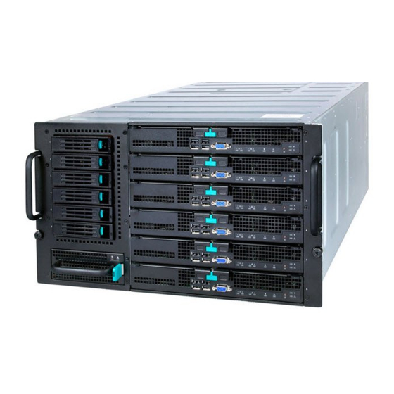
Page 53: Appendix D: Supported Intel Modular Server System
® Intel Modular Server System MFSYS25V2 ® Intel Modular Server System MFSYS35 This section provides a high-level pictorial overview of the Intel ® Modular Server System MFSYS25. For more details, refer to the Intel ® Modular Server System Technical Product Specification (TPS). -
Page 54: Glossary
Intel® Compute Module MFS5520VI TPS Glossary Glossary This appendix contains important terms used in the preceding chapters. For ease of use, numeric entries are listed first (for example, “82460GX”) followed by alpha entries (for example, “AGP 4x”). Acronyms are followed by non-acronyms. - Page 55 Glossary Intel® Compute Module MFS5520VI TPS Term Definition I/O and Firmware Bridge INTR Interrupt Internet Protocol IPMB Intelligent Platform Management Bus IPMI Intelligent Platform Management Interface Infrared In-Target Probe 1024 bytes Keyboard Controller Style Local Area Network Liquid Crystal Display...
- Page 56 Intel® Compute Module MFS5520VI TPS Glossary Term Definition SMBus System Management Bus Server Management Interrupt (SMI is the highest priority non-maskable interrupt) Server Management Mode Server Management Software SNMP Simple Network Management Protocol To Be Determined Thermal Interface Material UART...
-
Page 57: Reference Documents
Reference Documents Intel® Compute Module MFS5520VI TPS Reference Documents For additional information, refer to the Intel ® Modular Server System Technical Product Specification. Revision 1.5 Intel order number: E64311-007...
Need help?
Do you have a question about the MFSYS25V2 and is the answer not in the manual?
Questions and answers