Sign In
Upload
Manuals
Brands
Epson Manuals
Printer
Stylus Pro 4450
Epson Stylus Pro 4450 Manuals
Manuals and User Guides for Epson Stylus Pro 4450. We have
5
Epson Stylus Pro 4450 manuals available for free PDF download: Service Manual, User Manual, Setup Manual, Instruction Manual, Specifications
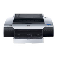
Epson Stylus Pro 4450 Service Manual (507 pages)
Brand:
Epson
| Category:
Printer
| Size: 79.51 MB
Table of Contents
Service Manual
1
Precautions
3
About this Manual
4
Manual Configuration
4
Symbols Used in this Manual
4
Revision Status
5
Table of Contents
6
Comparative Table
10
Comparison with Stylus Pro 4000
10
Features
11
Throughput (Stylus Pro 4400/4800)
11
Throughput (Stylus Pro 4450/4880/4880C)
11
Basic Specifications
13
Print Specifications
13
Character Specification
14
Control Code
14
Paper Feed Specification
14
Paper Feeder Specification
14
Paper Specification
15
Roll Paper
15
Cut Sheet
16
Special Paper
17
Availability with Roll Sheet
18
Mechanism Specifications
19
Printable Area
19
Borderless Print Specification
20
Borderless Print Specification Mode
20
Borderless Setting
20
Paper Set Lever
21
Cut Specification
21
Automatic Cut for Roll Paper
21
Cutting Conditions and Cutting Methods
21
Electrical Specification
22
Manual Cut for Roll Paper
22
Reliability
23
Environmental Conditions
23
Temperature/Humidity
23
Printer Life
23
Vibration
24
Shock
24
Surrounding Space
24
Quality Standards for Completed Products
25
Overall Dimensions
25
Noise
25
Time for Initial Ink Charge
25
Accessories
26
Ink Cartridge
26
External View and Parts Names
28
Operating Panel
30
Buttons and Functions
30
Led
30
LCD Panel
30
Switch
31
Panel Functions and Switch Operation
31
Panel Display in Operation (LCD and LED Display)
33
Paper Type Icon Display
38
PG Setting Display
38
Ink Remaining Indicator Display
38
Suction Adjustment and Indicator Display
38
Job Information
39
Panel Setting
40
Outline
40
Panel Display
41
Level Structure of Setting Menu
41
Level Structure of Printer Setting Menu
41
Level Structure of Test Print Menu
42
Level Structure of Printer Status Menu
42
Level Structure of User Paper Setup Menu
43
Level Structure of Maintenance Menu
43
Panel Setting Menu Item
44
Remaining Paper Detection
48
Level Structure of Remaining Roll Paper Menu
48
Level Structure of Remaining Cut Sheet Menu
48
PG Setting
49
Level Structure of PG Setting Menu
49
Relationships of PG Setting Values
49
Page Lines
50
Level Structure of Page Line Menu
50
Interface Select
51
Code Page Switching
51
Level Structure of I/F Switching
51
Level Structure of Code Page Switching
51
Roll Paper Margin
52
Level Structure for Roll Paper Margin Setting
52
Paper Width Detection
53
Level Structure for Detect Paper Width Menu
53
Skew Error Detection
54
Job Time-Out Setting
54
Level Structure of Detect Skew Error Menu
54
Level Structure of Job Timeout Setting Menu
54
Cutter Position Adjustment
55
Auto Margin Refresh
55
Level Structure of Cutter Position Adjustment Menu
55
Level Structure of Auto Margin Refresh
55
Cut Sheet Size Error
56
Auto Nozzle Check for each Job
56
Level Structure of Cut Sheet Size Error Menu
56
Level Structure of Auto Nozzle Check for each Job Menu
56
Cleaning Setting for Nozzle Check
57
Super Low Speed Cut Mode
57
Level Structure of Cleaning Setting for Nozzle Check Menu
57
Level Structure of Super Low Speed Cut Mode Menu
57
Printer Setup Value Initialization
58
Nozzle Check Pattern Printing
59
Status Printing
60
Status Sheet Print Pattern
60
Job Information Print
63
Job Information Print Pattern
64
User Paper Setting Printing
65
Firmware Version
66
Printable Pages Per Ink Cartridge
67
Level Structure of Printable Pages Per Ink Cartridge Menu
67
Ink Remaining
68
Level Structure of Remaining Ink Display
68
Maintenance Tank Count
69
Consumption Counter
69
Clear Consumption Counter
69
Job History Display
69
Consumable Life
70
Cutter Life
70
CR Motor Life
70
PF Motor Life
71
Head Unit Life
71
User Paper Setting
72
Cleaning Unit Life
72
Paper Setting and Corresponding Operation
73
Details of each Setting Items
74
Print Quality Setup Values Set by MW Print Adjustment
75
Level Structure of User Paper Menu
77
Paper Thickness Detection Pattern
78
Displacement of Paper Thickness Detection Pattern
78
Cutter Blade Replacement
79
K Ink Replacement
79
Power Cleaning
79
Gap Adjustment (Bi-D Adjustment, Uni-D Adjustment)
79
Adjustment
80
Level Structure of Gap Adjustment Menu
81
Gap Adjustment Print Pattern
82
Each Adjustment Item
82
Maintenance Mode 1
83
Startup
83
Termination
83
Aintenance Mode 1 Setup Items
84
Maintenance Mode 1 Setup Items
84
Hexadecimal Dump
86
Remaining Paper Display Setting
87
Unit Switching
87
Cutting Pressure
87
Panel Setting Initialization
87
Ink Information Menu
88
Level Structure of Ink Information Menu
89
Maintenance Mode 2
90
Self Testing Menu
91
Self Testing Menu List
91
Test Menu
95
Counter Display
97
Occurred Error Display
97
Counter Display Items and Units
97
Adjustment Menu
98
Print Menu
99
Nozzle Check Pattern
99
Print Menu Item
100
Adjustment Parameter Print Sample
100
Counter Display Menu
101
MIB Function
102
Corresponding MIB
102
Global MIB
102
Local MIB
102
Function to Prevent Irregular Printing
103
Strong Cancel Data
103
Skip Reading of Irregular Data
103
Initialization
104
Default Setup Values
104
Hardware Initialization
104
Software Initialization
104
Controller
105
USB Interface
106
Specification
106
Signal Assignment and Signal Definition of Input Connector PIN
106
IEEE1394 Interface
107
Protocol
107
Chapter 1 Product Description
107
Optional Interface
108
Reply Message
108
Reply for Option Command
108
Supported Main Command and Sending Timing
109
Sending BDC-ST Character Strings Via DBIN-Register
109
Type-B Level 3 Packet Mode
109
Supported Channel
109
Supplements
110
Received Buffer Full Operation
110
Interface Selection
110
Optional Units and Consumables
111
Ink Cartridge
111
Cleaning Cartridge
112
Maintenance Tank
112
Chapter 2 Operating Principles
113
Operating Principles
114
Overview
114
Printer Mechanism Components
115
Printing Mechanism (Print Head)
116
Relationships of Colors to Nozzles by Mode
116
Relationship between Nozzle Rows and Colors
116
Printing Modes (Drive Waveforms)
117
Ink Supply Mechanism
118
Csic
118
Valve Mechanism
118
Dumper
119
I/H Lever Sensor
119
Ink Route Inside of Dumper
119
Cleaning Mechanism
120
Cleaning Mechanism Components
120
Cleaning Mechanism Drive
121
Drive Transmission Path
121
Cleaning Mechanism Drive Layout
121
Cleaning Mechanism Drive Components
121
Drive Transmission to Pump Unit
122
Switching Drive Transmission Path
122
Asf/Pump Motor Rotation Directions and Functions
123
Pump Phase Sensor
123
Explanation of Operation
124
Carriage (CR) Mechanism
125
Carriage Mechanism Components
125
Carriage Unit Movement Components
126
Carriage Mechanism Drive
126
Carriage Mechanism Drive Components
126
Carriage Mechanism Detection Components
127
Platen Gap Adjustment Components
128
Platen Gap Mechanism
128
Platen Gap Mechanism Drive Components
128
Drive Transmission to Carriage Shaft
129
PG/PO Motor (Stepping Motor)
130
PG Phase Sensor
130
PG/PO Motor Rotation Directions and Functions
130
PG Setting Positions
130
Paper Feed Mechanism
131
Cutter Solenoid/Cr Lock Mechanism
131
Carriage Components: Cutter Solenoid
131
Paper Feed Mechanism Drive
132
Paper Feed Mechanism Drive Layout
132
Paper Feed Mechanism Drive Components
132
Suction Fans
133
Modes
133
ASF Paper Feed Mechanism
134
Rear Manual Insertion Sensor
134
Paper Feed Mechanism Sensors
134
ASF Paper Feed Mechanism Drive
135
ASF Paper Feed Mechanism Drive Layout
135
ASF Paper Feed Mechanism Drive Components
135
Transmission of Drive to ASF Unit
136
Asf/Pump Motor
137
ASF Paper Sensor
137
ASF Phase Sensor
137
Lifter Movement
138
Paper Eject/Release Mechanism
140
Paper Mechanism Drive
140
Paper Eject Mechanism Drive Layout
140
Paper Eject Mechanism Drive Components
140
Transmission of Drive to Paper Eject Unit
141
Paper Eject Phase Sensor
142
Paper Eject Release Sensor
142
Paper Eject Switching Movement
142
Paper Eject Unit
142
Release Mechanism
143
Release Mechanism Drive
143
Release Mechanism Drive Layout
143
Release Mechanism Drive Components
143
Release Mechanism Movement
144
Multi Sensor
145
Light Receivers
145
Operations/Functions
146
Sensor Sensitivity Adjustment
146
Paper Top Edge Detection
146
Checking Paper Cut
146
Paper Left/Right Edge Detection During Printing
147
Paper Width Detection Timing
147
Dot Missing Detection
148
Automatic Uni-D Adjustment
148
Automatic Bi-D Adjustment
149
Rough Adjustment Pattern
149
Fine Adjustment Pattern
150
Fine Adjustment Pattern Detection
150
Others
151
P-Cover Open Sensor
151
Rear Cover Sensor
151
Circuit Board Layout
151
Outline of Control Circuit Board
152
Major Elements
152
C593 Main Board – Circuit Block Diagram
152
CA00 Main Board - Circuit Block Diagram
153
Outline of Power Supply Circuit Board
154
Operational Descriptions
154
Colorimetric Calibration (Color ID) Overview
155
Colorimetric Calibration (Color ID) Image
155
Chapter 3 Troubleshooting
156
Check before Troubleshooting
157
Narrow down the Trouble
157
Troubleshooting Outline
157
Troubleshooting Based on Panel Messages
158
Message Table
158
Displayed Error Messages
158
Service Request Error List
161
Corrective Actions for Displayed Warnings
162
Maintenance Tank Near
162
Ink Low
162
Maintenance Request
162
Corrective Actions for Error Display
165
Corrective Actions for Service Request Display
175
Diagnosing Trouble Based on Printout
196
Troubleshooting Based on Your Printout
196
Cautions
201
Disassembly and Assembly Introductory Information
201
Directional View of the Printer
203
Required Tools
203
Tools
203
Screws
204
4.1.4 Difference between 8-Color and 4-Color Models in Disassembly/Assembly
205
Disassembly Procedures
206
Basic Operations
207
Release of the Transport Retaining Lever
207
Open Cover, Printer
207
Print Head Lock Release
207
Carriage Unit Lock Release/Lock Set Method
208
Consumable Parts/Asf Cassette Removal
209
Ink Cartridges
209
Ink Cartridge Lock Release
209
Ink Cartridge Removal
209
Maintenance Tank (Porous Pad Assy., Ink Eject)
210
Maintenance Tank Removal
210
Cutter Assembly
211
Cutter Assembly Removal
211
ASF Cassette
212
ASF Cassette Removal
212
Spindle
213
Spindle Removal
213
Spindle Disassembly
213
Panel Unit/Housing Removal
214
Holder, Roller, Unit
214
Screws Securing Holder, Roller, Unit
214
Holder, Roller, Unit Removal
214
Paper Guide Assy., M, SP
215
Paper Guide Assy., M, SP Removal
215
Cover, Side, Left
216
Cover, Side, Left Removal
216
Cover, Side, Right
217
Paper Lever Removal
217
Cover, Side, Right Removal
218
Panel, Front/Panel Unit
219
Panel, Front Removal
219
Panel Unit Removal
220
Cover, Printer
221
Plate, P Cover, Left Removal
221
Cover, Printer Removal
222
Cover, Rear
223
Cover, Rear Removal
223
P Cover Open Sensor
224
P Cover Open Sensor Removal
224
Removing the Rear Cover Sensor Unit
225
Connector Connecting Status
225
Tabs Securing Rear Cover Sensor
225
Circuit Board Removal
226
C593 MAIN Board
226
Screws Securing the Cover, Harness
226
Cover, Harness Removal
226
Pulling out the PCB Unit
227
Connectors/Harnesses Connected to C593 MAIN Board
228
"C593MAIN Board" Connector Positions
228
Cover, I/F and Grounding Board, I/F Removal
230
Guide Rail Removal
231
Bracket Removal
231
C593 MAIN Board Removal
232
Power Supply Board / Power Supply Cooling Fan
233
Power Supply Cooling Fan Removal
233
Power Supply Board Removal
233
C593_SUB Board
234
Moving the Carriage Unit
234
Carriage Cover Removal
234
Connectors/Harnesses Connected to C593_SUB Board
235
C593_SUB Board Removal
235
C511_SUB-B Board
236
Connectors/Harnesses Connected to C511_SUB-B Board
236
C511_SUB-B Board Connector Positions
236
C511_SUB-B Board Removal
237
C593_SUB-C Board
238
Releasing FFC
238
C593_SUB-C Board Connector Locations
238
SUB-C Board Removal
239
C593_SUB-D Board
240
Connectors/Harnesses Connected to C593_SUB-D Board
240
C593_SUB-D Board Connector Positions
240
C593_SUB-D Board Removal
240
Printer Mechanism Disassembly
241
Printer Mechanism (SP)
242
Parts Configuration
242
Fan, Blower
244
Paper Guide, Eject, Stacker Removal
244
Releasing Relay Harness
244
Frame, Fan, Unit Removal
245
Asf
246
ASF Unit
246
"Joint Plate" Attachment
247
"Base, Left" Setting
247
"Base, Right" Setting
248
"Stand" Setting
250
Screws Securing "ASF Unit"
251
"ASF Unit" Removal
253
Roller Assy., LD, Left / Roller Assy., LD, Right
254
"Gear, 44.47" and "Lever, Hopper, Release" Removal
254
Screws Securing "Frame, ASF, Right"
255
"Frame, ASF, Right" Removal
255
"Wheel, Detector" Removal
255
"Bushing, Lock, 11.4" Removal
256
Holder, Edge Guide, Left Removal
257
Roller Assy., LD, Left Removal
257
"Roller Assy., LD, Left" and "Roller Assy., LD, Right" Removal
258
Mount Assy., Plate, Motor, ASF, SP
259
Spur Gear, 16 Removal
259
Mount Assy., Plate, Motor, ASF, SP Removal
260
Cover, Motor, PF Removal
263
Wheel, Detector Removal Position
263
Wheel, Detector Removal
264
ASF Phase Sensor Removal
264
ASF Paper Sensor Removal
265
Carriage Mechanism
266
Carriage Unit
266
Screws Securing Ink Tube Unit
266
Releasing Tabs on the Bottom of Ink Tube Unit
266
"Lever, Inclination" Removal
268
Removal of Screw Securing Head Unit
268
Head Unit Removal
268
Carriage Unit Removal
269
Motor Assy., CR
270
Disconnecting the CR Motor Connector
270
Releasing Tension of Belt, CR
270
Harness, CR
272
Releasing the Harness
272
Motor Assy., PG
274
Sheet, Ink, Stopper, C Release
274
Motor Assy., PG Removal
275
CR_HP Sensor
276
CR_HP Sensor Removal
276
Screws Securing Multi Sensor
277
Multi Sensor Removal
277
Connecting Status of Multi Sensor Connector
277
Rotating the Shield Plate
278
Extension Spring, 2.58 Removal
279
PG Phase Sensor Removal
279
CR Encoder Sensor
280
CR Encoder Sensor Removal
280
Scale, CR
281
Scale, CR Removal
281
Pulley, Driven/Shaft, Pulley
282
E-Ring and Plain Washer Removal
282
Loosening CR Tension
282
"Shaft, Pulley" Removal
283
Pulley, Driven and Shaft, Pulley Removal
283
Solenoid, CR
284
"Solenoid, CR" Removal
284
Ink System
285
Printhead
285
CR SUS Plate Support Tool Set Position
286
"Belt, CR" Removal
286
Head Exchange Support Tool Setting
287
Carriage Unit Setting / Screws Securing Carriage, C
288
"Carriage, C" Removal
289
Separation from Carriage, B
289
Printhead Removal
290
Harness, Head Removal
290
Valve Assy., Head
291
Tube, Supply, Ink Removal
291
"Plate, Damper" Drawing
293
"Valve Assy., Head" Removal
293
Gutter, Ink
294
Duct, Air, D Removal
294
Duct, Air, a and Gutter, Waste Ink Removal
294
Screw Securing Gutter, Ink
295
Gutter, Ink Removal
295
I/H Left Unit / I/H Lever Sensor (Left)
296
Cover, I/H, Left Removal
296
I/C, Lock Lever, Knob, Left Removal
296
Guide, I/H, Left Removal
297
Installation Plate, I/H Guide, a Removal
297
Installation Plate, I/H Guide, C Removal
298
Releasing the Tube, Supply, Ink
299
I/H Left Unit Front Side
299
Screws Securing Rear Side of I/H Left Unit
300
Releasing the Harnesses
301
I/H Left Unit Removal
301
I/H Lever Sensor (Left) Removal
303
Cover, Holder, IC, Left Removal
303
I/H Right Unit / I/H Lever Sensor (Right)
305
Cover, I/H, Right Removal
305
I/C, Lock Lever, Knob, Right Removal
305
Screws Securing Guide, I/H, Right
306
Installation Plate, I/H Guide, B Removal
306
Releasing Harnesses
309
Screws Securing Rear Side of I/H Right Unit
312
Screws Securing Front Side of I/H Right Unit
312
I/H Right Unit Removal
313
I/H Lever Sensor (Right) Removal
313
Cover, Holder, IC, Right Removal
314
Box Assy., Flushing / Pump Unit
316
Box Assy., Flushing Removal
316
Shaft, Transmission, PG Unit Removal
317
Extension Spring, 0.262 Removal
318
Lever, Lock, Planetary Removal
318
Lever, Lock, de Removal
319
Disconnecting the Pump Phase Sensor Connector
320
Screws Securing Pump Unit
320
Pump Unit Removal
320
Guide, Waste Ink
322
Guide, Waste Ink Removal
322
Screws Securing the Pump Cover
323
Pump Cover Removal
323
Pump Phase Sensor Removal
324
Holder, FFC
325
Holder, FFC Removal
325
Holder, FFC Tabs Release
326
"Holder, FFC" Removal
326
Harness, Head, Intermit / Harness, Head
331
FFC Release
331
Release from Cover, Tube
331
Holder, FFC, CR Removal
332
Harness, Head, C Removal
332
Harness Head Removal
333
Harness, Head, Intermit
334
Tube, Supply, Ink (Y/M/C/MK) on the Left Side of the Main Unit
335
Coupling Screw, M7 Removal
335
"Tube, Supply, Ink" Release
335
Separation Holder, Tube, a from Holder, Tube, B
336
Tube, Supply, Ink Release
337
Cover, Tube Removal
337
Tube, Supply, Ink (LK/LC/LW/LLK) on the Right Side of the Main Unit
339
Holder, Tube, a and Holder, Tube, B Separation
340
Release Unit
343
Cover, Inner, Release Removal
343
Plate, P Cover, Right Removal
343
Paper Feed Mechanism
343
Release, Lever Unit and Spur Gear, 18 Removal
344
Intermittent Gear, 40 Removal
345
PT Sensor Unit Removal
346
Guide, Roll Paper and Installation Plate, Detector, Rear Removal
346
Release Unit Removal
347
Screws Securing the Paper Eject Unit
348
Paper Eject Unit Removal
348
Motor Assy., PF
349
Releasing Guide, FFC
349
Releasing Tension of Belt, Motor, PF
350
Motor Assy., PF Removal
350
P Thick Sensor (0.8/0.3)
351
P Thick Sensors Removal
351
PE Sensor
352
Holder, Detector, PE Removal
352
PE Sensor Removal
353
Installation Plate, Detector, Rear Removal
354
Rear Manual Insertion Sensor Removal
355
Paper Eject Phase Sensor Removal
356
Paper Eject Release Sensor Removal
356
PF Encoder Sensor
357
PF Encoder Sensor Removal
357
Harness Routing
358
Harnesses on Left Side of Printer
358
PG Sensor Harness
358
CSIC / I/H Lever Sensor Harness
358
Harness, Head/Harness, R1/R2
359
Head FFC / Intermit FFC
359
Harnesses on Right Side of Printer
360
Routing on the Right Frame
360
Routing on the "Duct, Air, C"
361
Joint, Supply, Ink Removal
362
Disassembly/Assembly Unique to 4-Color Model (Stylus Pro 4000)
362
Cover, Front, Right 4 Color
365
Cover, Front, Right 4 Color Removal
365
Adjustment Overview
367
Advance of Adjustment
367
The Part/Unit that Requires Adjustment
367
Cautions
367
Adjustment Items Classified by Part/Unit
368
Required Adjustment Items/Execution Order
368
Adjustment Item
371
Mechanical Adjustment
371
Standard Adjustment
371
Advanced Adjustment
372
Check Results
373
Reset Counters
373
Adjustment Tools
374
Adjustment Program Basic Operation
375
Start-Up
375
Sequential Mode
375
Individual Adjustment Mode
375
CR Timing Belt Tension Adjustment
376
Setting the Tension Measurement Tool
376
Mechanical Adjustment
376
PF Timing Belt Tension Adjustment
378
Chapter 4 Disassembly & Assembly
378
Paper Thickness Sensor Adjustment
380
CR Encoder Sensor Position Adjustment
382
Chapter 5 PG Adjustment
383
Screws Securing Bush, Shaft, Rear
383
Multi Sensor Position Adjustment
385
Setting the Position Tool
385
Setting the CR Lock Tool
386
Basic Adjustment
387
Difference between 8-Color and 4-Color Models in Disassembly/Assembly 5.3.1 RTC&USB ID&IEEE1394 ID
387
IEEE 1394 ID Label
387
205 5.3.2 Head Rank ID
388
Procedure for Saving the Head Rank ID Information
388
Procedure for Writing
388
Multi Sensor Level Adjustment
389
Multi Sensor Level Adjustment Values
389
Adjustment Pattern
390
T&B&S (Roll Paper)
390
T&B&S (Cut Sheet)
391
T&B&S (Cut Sheet) Screen
391
Cutter Pressure Adjustment
392
Nozzle Bi-D Adjustment
393
Nozzle Bi-D Adjustment Check Pattern
393
Nozzle Bi-D Adjustment Screen
393
Print Head Slant Adjustment (PF)
394
Print Head Slant Adjustment (PF) Screen
394
Head Fixing Screws and the Cam , Inclination, R.3
396
Print Head Slant Adjustment (CR)
397
Screens Shift for Print Head Slant Adjustment (CR)
397
Head Fixing Screws and Lever, Cam
399
Checking the Dots Position
400
Auto Uni-D Adjustment
401
Auto Uni-D Adjustment Pattern
401
Auto Uni-D Adjustment Screen
401
Multi Sensor Adjustment for Auto Nozzle Check
402
Multi Sensor Adjustment for Auto Nozzle Check Screen
402
Check Pattern (Dot Missing)
403
Check Pattern (no Dot Missing)
403
Skew Check
404
Skew Check Screen
404
Platen Position Adjustment
405
Platen Position Adjustment Screen
405
Check Pattern
406
1000Mm Feed Adjustment
407
1000Mm Feed Adjustment Pattern
407
1000Mm Feed Adjustment Screen
407
Initial Ink Charge Flag ON/OFF
408
Initial Ink Chrge Flag ON/OFF Screen
408
NVRAM Back up and Write
409
NVRAM Backup Utility
409
Read and Save Procedure
409
Write Procedure
409
Check Platen Gap
410
Ink Discharge
411
Cleaning
412
Initial Ink Charge
412
Rear Sensor Adjustment
413
Setting the Microtrace
413
Colorimetric Calibration (Color ID)
414
Adjusting Method
415
Adjustment Workflow
415
Tools Required
415
Adjustment Procedure (Entire Process Workflow)
416
Colorimetric Calibration ID Startup Screen
416
Entire Process Screen
417
I1 Calibrator
418
Measurable Time and Date Check
419
Setting the Chart and the Scanning Ruller
419
Color Measuring Screen
420
Color Measuring Order
421
Setting the Calibrator/Measuring Position
421
Measurable Date and Time Check
424
Setting the Chart and the Scanning Ruler
424
Setting the Calobrator/Color Measuring Position
425
Adjustment Procedure (Separate Workflow)
427
Printing Calibration Chart
427
Creating Color ID Data (at Color Measuring Site)
428
Generating Colorimetric Calibration ID Data
428
Writing Color ID (at Repair Work Site)
429
Writing Colorimetric Calibration ID
429
Auto Bi-D Adjustment
430
Auto Bi-D Adjustment Screen
430
Advanced Adjustment
430
Manual Bi-D Adjustment
431
MK Adjustment Pattern
432
Manual Bi-D Adjustment Screen
433
Color Adjustment Pattern
433
Destination Setting
434
Destination Setting Screen
434
Confirming Model Name
434
PF Micro Feed Adjustment (Bi-D) (TBD)
435
Check Nozzle
436
Check Nozzle Screen
436
Check Results
436
Check Alignment
437
Check Alignment Screen
437
Horizontal Alignment Check Pattern
437
Vertical Alignment Check Pattern
437
Print Adjustment Check Pattern
438
Print Adjustment Check Pattern Screen
438
Image Printing
439
Image Printing Screen
439
Check Cutting
440
Check Cutting Screen
440
Reset Paper Ejection Switching/Pg Switching Counter
441
Reset PF Motor Counter
441
Reset Paper Ejection Switching/Pg Switching Counter Screen
441
Reset PF Motor Counter Screen
441
Reset ASF Counter
442
Reset When CR Unit Change
442
Reset ASF Counter Screen
442
Reset When CR Unit Change Screen
442
Reset When Cleaning Unit Change
443
Reset When Printhead Change
443
Installing Firmware
444
Firmware Update Tool Screen
444
Installing Firmware for SP 4400 (4-Color Model) after Replacing Main Board with New One
445
Device ID Setting
446
[Select Printer Name] Screen
446
[Port Check on Connected Printer] Screen
446
Writing MAC Address
447
Location of the Label with MAC Address
447
[Set MAC Address] Window
447
Confirmation Window of [Set MAC Address]
447
Advertisement
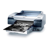
Epson Stylus Pro 4450 User Manual (338 pages)
Professional 17-inch printer
Brand:
Epson
| Category:
Printer
| Size: 6.14 MB
Table of Contents
Copyrights and Trademarks
2
Front View
3
Printer Parts
3
Rear View
3
Table of Contents
4
Important Safety Instructions
9
Warning, Cautions, and Notes
9
When Choosing a Place for this Product
9
When Setting up this Product
10
When Using this Product
12
When Handling the Ink Cartridges
12
When Transporting this Product
14
ENERGY STAR ® Compliance
14
Safety Instructions
9
Chapter 1 Using the Printer Software (Windows)
15
Printer Software Introduction
15
Printer Driver
15
EPSON Status Monitor 3
17
EPSON LFP Remote Panel
17
Accessing the Printer Driver
18
From Windows Applications
18
From the Printer Icon
21
Getting Information through Online Help
23
Basic Settings
25
Setting the Printer Driver
25
Checking the Printer Status
26
Canceling Printing
27
When Problem Occurs During Printing
30
Using the Printer Utilities
31
Using EPSON Status Monitor 3
33
Accessing Epson Status Monitor 3
34
Uninstalling the Printer Software
38
Uninstalling the Printer Driver
38
Uninstalling EPSON LFP Remote Panel
40
Chapter 2 Using the Printer Software (Mac os X)
41
Printer Software Introduction
41
Printer Driver
41
EPSON Printer Utility2
42
EPSON Statusmonitor
43
EPSON LFP Remote Panel
44
Accessing the Printer Driver
44
Accessing the Page Setup Dialog
45
Accessing the Print Dialog
46
Getting Information through Online Help
47
Basic Settings
48
Setting the Printer Driver
48
Checking the Printer Status
49
Canceling Printing
50
When Problem Occurs During Printing
52
Using Printer Utilities
53
Accessing EPSON Printer Utility2
54
Using EPSON Statusmonitor
55
Uninstalling the Printer Software
57
Uninstalling the Printer Driver
57
Uninstalling EPSON LFP Remote Panel
61
Chapter 3 Variety of Printings
62
Using Color Management
62
Color Management
63
Color Management by Application
65
Color Adjustment by the Printer Driver
76
Black-And-White Photo Printing
82
Borderless Printing
86
Supported Media Type
88
Application Settings
90
Printer Driver Settings
91
Roll Paper Cut for Borderless Printing
97
Enlarge or Reduce Size Printing
99
Fit to Page (Windows Only)
101
Fit to Roll Paper Width (Windows Only)
103
Custom
106
Pages Per Sheet Printing
108
For Windows
109
For Mac os X
110
Poster Printing
111
Joining the Sheets Together Along the Guide
115
Printing on Custom Paper
121
For Windows
122
For Mac os X
124
Banner Printing on Roll Paper
127
Application Settings
128
Printer Driver Settings
128
Printing with Non-Epson Media
134
Customize the Items of the Printer Driver
135
Saving the Printer Driver Settings
135
Menu Arrangement
139
Exporting or Importing
142
Chapter 4 The Control Panel
145
Buttons, Lights, and Messages
145
Buttons
145
The Control Panel
146
Lights
147
Combination of Buttons
148
Messages
149
Menu Settings
150
When to Use Menu Mode
150
Menu List
151
Basic Menu Setting Procedure
157
Details of Menu Mode
158
Platen Gap
159
Drying Time
168
Checking the Print Head Nozzles
173
Aligning the Print Head
175
Aligning the Print Head Manually
180
Making the Paper Settings
183
Printing a Status Sheet
186
Setting the Alert Value of the Paper
187
Maintenance Mode
188
Maintenance Mode Setting Procedure
188
Maintenance Mode List
189
Details of Maintenance Mode Items
190
Menu Button
191
Chapter 5 Paper Handling
193
Notes on Epson Special Media and Other Media
193
Using Epson Special Media
193
Using Paper Other than Epson Special Media
194
Using Roll Paper
195
Attaching the Roll Paper to the Spindle
195
Attaching the Spacer to the Spindle
197
Removing the Roll Paper from the Spindle
198
Loading Roll Paper
199
Using the Roll Paper Belt
203
Cutting the Roll Paper or Printing Page Lines
203
Using Cut Sheet Media
206
Checking the Paper Path
206
Loading Cut-Sheet Media
207
Loading Paper into the Front Manual Feed Slot
218
Loading Paper into the Rear Manual Feed Slot
224
Chapter 6 Maintenance and Transportation
226
Replacing Ink Cartridges
226
Converting the Black Ink Cartridges
231
Updating the Printer Driver Information
238
Replacing the Maintenance Tank
239
Replacing the Paper Cutter
240
Cleaning the Printer
245
If You Have Not Used Your Printer for a Long Time
249
Transporting the Printer
250
Over a Long Distance
250
Over a Short Distance
252
Setting up the Printer after Transporting It
252
Chapter 7 Problem Solver
254
Troubleshooting
254
Printer Stops Printing Unexpectedly
254
Error Messages
255
The Printer Does Not Turn on or Stay on
262
The Printer Prints Nothing
263
Printouts Are Not What You Expected
265
Print Quality Could be Better
268
Color Documents Print in Black Only
272
Printing Could be Faster
272
Roll Paper Cannot be Cut
273
Paper Feed or Paper Jam Problems Occur Frequently
274
Roll Paper Does Not Eject Properly
275
Clearing Paper Jams
276
Contacting Customer Support
288
Technical Support
293
Product Information
295
Help for Users in India
297
Paper Information
299
Roll Paper
301
Cut Sheets
307
Technical Support Web Site
313
Chapter 8 Product Information
314
Printer Specifications
314
Printing
314
Printable Area
316
Mechanical
317
Electrical
318
Environmental
318
Standards and Approvals
319
Paper
320
Ink Cartridges
322
System Requirements
324
To Use Your Printer with Windows
324
To Use Your Printer with Mac os X
325
Interface Specifications
326
USB Interface
326
Ethernet Interface
326
Epson Stylus Pro 4450 Setup Manual (16 pages)
Professional 17-inch printer
Brand:
Epson
| Category:
Printer
| Size: 0.59 MB
Table of Contents
Table of Contents
1
Printer Parts
2
Front View
2
Rear View
2
Safety Instructions
3
Assembling the Printer
4
Setting up the Printer
5
Installing the Paper Tray
6
Installing the Ink Cartridges
6
Loading Roll Paper
8
Loading Cut-Sheet Paper
10
Loading Paper into the Rear Manual Feed Slot
12
Connecting the Printer with Your Computer
13
Installing the Printer Driver and Software
14
Using the Online User's Guide
15
Advertisement
Epson Stylus Pro 4450 Instruction Manual (13 pages)
Subli-Print
Brand:
Epson
| Category:
Printer
| Size: 2.15 MB
Epson Stylus Pro 4450 Specifications (4 pages)
Expand Your Business with Faster Turnaround and Higher Image Quality
Brand:
Epson
| Category:
Printer
| Size: 0.68 MB
Advertisement
Related Products
Epson pro4880gd
Epson Stylus Pro 4800 Portrait Edition
Epson Stylus Pro 4400
Epson Stylus Pro 4880C
Epson Stylus Pro 4880 Portrait Edition
Epson Stylus Pro 4900
Epson Pro 4910
Epson Stylus Pro WT7910
Epson STYLUS PRO 10600CF
Epson Stylus Pro 11880C
Epson Categories
Printer
Projector
All in One Printer
Scanner
Printer Accessories
More Epson Manuals
Login
Sign In
OR
Sign in with Facebook
Sign in with Google
Upload manual
Upload from disk
Upload from URL