Sign In
Upload
Manuals
Brands
Basler Manuals
Relays
BE1-11g
Basler BE1-11g Manuals
Manuals and User Guides for Basler BE1-11g. We have
2
Basler BE1-11g manuals available for free PDF download: Instruction Manual, Quick Start Manual
Basler BE1-11g Instruction Manual (706 pages)
Generator Protection System
Brand:
Basler
| Category:
Protection Device
| Size: 21 MB
Table of Contents
Table of Contents
5
Introduction
13
Applications
13
Features
14
Model and Style Number Description
20
Quick Start
23
Maintenance
23
Storage
23
Install Bestcomsplus® Software
23
Power up and Activate the BE1-11 Plug-In
24
Programming the BE1-11G
28
Controls and Indicators
37
Illustrations and Descriptions
37
Menu Navigation
40
Front Panel Operations
40
Display Setup
42
Contact Inputs and Outputs
45
Contact-Sensing Inputs
45
Contact Outputs
49
Overexcitation (24) Protection
55
Element Operation
55
Logic Connections
57
Operational Settings
58
Settings Example
59
Sync-Check (25) Protection
63
Element Operation
63
Logic Connections
66
Operational Settings
66
Phase Undervoltage (27P) Protection
69
Element Operation
69
Logic Connections
72
Operational Settings
72
Auxiliary Undervoltage (27X) Protection
75
Element Operation
75
Logic Connections
78
Operational Settings
79
Negative-Sequence Voltage (47) Protection
81
Phase Overvoltage (59P) Protection
83
Element Operation
83
Logic Connections
86
Operational Settings
86
Auxiliary Overvoltage (59X) Protection
89
Element Operation
89
Logic Connections
92
Operational Settings
92
Stator Ground (64G) Protection
95
Vector Jump (78V) Protection
97
Element Operation
97
Logic Connections
98
Operational Settings
98
Frequency (81) Protection
101
Frequency Measurement
101
Underfrequency and Overfrequency Protection
101
Frequency Rate-Of-Change Protection
102
Logic Connections
104
Operational Settings
104
Negative-Sequence Overcurrent (46) Protection
107
Pickup Settings
107
Coordination Settings
108
Instantaneous Overcurrent (50) Protection
109
Element Operation
109
Logic Connections
111
Operational Settings
111
Breaker Failure (50BF) Protection
113
Element Operation
113
Logic Connections
115
Operational Settings
115
Inverse Overcurrent (51) Protection
117
Element Operation
117
Logic Connections
122
Operational Settings
122
Directional Overcurrent (67) Protection
125
Polarization Methods
125
Maximum Torque Angle and Directional Tests
127
Theory of Using Sequence Impedances for Fault Direction
128
Phase Current Differential (87) Protection
131
Element Operation
131
Logic Connections
135
Settings
135
Neutral Current Differential (87N) Protection
139
Element Operation
139
Logic Connections
141
Operational Settings
142
Phase Differential Protection: Self-Balancing and Split-Phase Configurations (50/51)
143
Self-Balancing
143
Split-Phase
144
Power (32) Protection
145
Element Operation
145
Logic Connections
148
Operational Settings
148
Loss of Excitation - Reverse Var Based (40Q) Protection
151
Element Operation
151
Logic Connections
152
Operational Settings
153
Distance (21) Protection
155
Element Operation
155
Logic Connections
156
Operational Settings
156
Loss of Excitation - Impedance Based (40Z) Protection
159
Element Operation
159
Logic Connections
160
Operational Settings
161
Typical Application
162
Out of Step (78OOS) Protection
163
Element Operation
163
Logic Connections
164
Operational Settings
165
Resistance Temperature Detector (49RTD) Protection
167
Element Operation
167
Logic Connections
168
Operational Settings
168
Remote RTD Metering
169
Analog Input Protection
171
Element Operation
171
Logic Connections
172
Operational Settings
172
Remote Analog Input Metering
173
Synchronizer (25A)
175
Element Operation
175
Logic Connections
179
Operational Settings
181
Virtual Control Switches (43)
183
Element Operation
183
Logic Connections
185
Operational Settings
185
Logic Timers (62)
187
Element Operation
187
Logic Connections
190
Operational Settings
190
Lockout Functions (86)
193
Element Operation
193
Logic Connections
193
Operational Settings
193
Retrieving Lockout Status from the BE1-11G
194
Breaker Control Switch (101)
195
Element Operation
195
Logic Connections
196
Operational Settings
197
Setting Groups
199
Setting Group Functions
199
Logic Connections
202
Operational Settings
203
Logic Override of the Setting Group Selection Function
205
Metering
207
Metering Explorer
207
Analog Metering Functions
208
Sequence of Events
215
Sequence of Events Setup
215
Retrieving SER Information
216
Fault Reporting
217
Fault Reporting Trigger Logic
217
Targets
217
Fault Reports
222
Oscillographic Records
226
Distance to Fault
227
Protective Fault Analysis
229
Alarms
231
Alarm Settings
233
User Programmable Alarms
233
Retrieving Alarm Information
234
Resetting Alarms
234
Differential Reporting
237
Breaker Monitoring
239
Breaker Status Reporting
239
Breaker Duty Monitoring
240
Breaker Alarms
244
Demands
245
Current
245
Power
246
Retrieving Demand Reporting Information
246
Load Profile
249
Setting the Load Profile Recording Function
249
Retrieving Load Profile Recorded Data
249
Power Quality
251
Power Quality Settings
251
Retrieving Power Quality Data
251
Trip Circuit Monitor (52TCM)
255
Element Operation
255
Logic Connections
260
Operational Settings
260
Fuse Loss (60FL)
263
Element Operation
263
Logic Connections
265
Operational Settings
265
Bestnet™Plus
267
Status Page
267
Real Time Data
267
Demand Data
268
Faults
269
Sequence of Events
271
Power Quality
271
Mounting
273
J Type Case Cutouts and Dimensions
273
H or P Type Case Cutouts and Dimensions
281
Dovetailing Procedure
288
Terminals and Connectors
291
J Type Case
291
H or P Type Case
294
CT Polarity
295
Typical Connections
299
Power System Applications
305
Bestcomsplus® Software
311
Installation
312
Activate the BE1-11 Plugin for Bestcomsplus
312
Menu Bars
317
Settings Explorer
319
Metering Explorer
320
Settings File Management
320
Auto Export Metering
322
Bestcomsplus® Updates
323
Firmware Updates
323
Bestlogic™Plus
325
Overview of Bestlogic™Plus
325
Logic Schemes
336
Programming Bestlogic™Plus
340
Offline Logic Simulator
341
Bestlogic™Plus File Management
342
Bestlogic™Plus Examples
343
Communication
345
Connections
345
Ethernet Setup
346
Email Setup
348
RS-485 Setup
349
DNP Setup
349
Modbus Setup
353
Security
355
Access Levels
355
Username Setup
355
Port Access Setup
356
Access Control
357
Viewing the Security Log
358
Authenticity and Encryption
359
Timekeeping
363
Clock Setup
363
Setting the Time and Date
365
IRIG Port
365
Real-Time Clock Specifications
365
Backup Battery for the Real-Time Clock
366
Device Information
371
Style Number
371
Device Info
372
Firmware Updates
372
Configuration
375
Power System Measurements
375
Power System Settings
378
Sensing Transformers Settings
380
Transformer Setup
382
Display Units
391
Introduction to Testing
393
Testing Philosophies
393
Testing and Troubleshooting Aids
394
Acceptance Testing
397
Test Equipment
397
Power up
397
Communications
397
Style Number and Serial Number Verification
397
IRIG Verification (if Used)
398
Contact Sensing Inputs
398
Control Outputs
398
Current Circuit Verification
399
Three-Phase Voltage Circuit Verification
400
Power Reading Verification
401
Auxiliary Voltage Input Verification - VX and VX 3
401
Rd (Fundamental and Third Harmonic)
401
Frequency Verification
402
Commissioning Testing
403
Digital I/O Connection Verification
403
Virtual Selector Switches
404
Virtual Control Switch
404
Protection and Control Function Verification
405
Verify Other Setpoints as Appropriate
405
Reporting and Alarm Functions
405
Periodic Testing
409
Settings Verification
409
Analog Circuit Verification
409
Overexcitation (24) Test
411
Functional Test Procedure
411
Functional Test Report
415
Sync-Check (25) Test
417
Functional Test Procedure
417
Functional Test Report
420
Phase Undervoltage (27P) Test
423
Functional Test Procedure
423
Functional Test Report
425
Auxiliary Undervoltage (27X) Test
427
Functional Test Procedure
427
Functional Test Report
436
Phase Overvoltage (59P) Test
439
Functional Test Procedure
439
Functional Test Report
441
Auxiliary Overvoltage (59X) Test
443
Functional Test Procedure
443
Functional Test Report
451
Vector Jump (78V) Test
455
Functional Test Procedure
455
Functional Test Report
456
Frequency (81) Test
459
Functional Test Procedure
459
Functional Test Report
464
Instantaneous Overcurrent (50) Test
467
Functional Test Procedure
467
Functional Test Report
474
Breaker Fail (50BF) Test
477
Functional Test Procedure
477
Functional Test Report
480
Inverse Overcurrent (51) Test
481
Functional Test Procedure
481
Functional Test Report
490
Directional Overcurrent (67) Test
497
Functional Test Procedure
497
Functional Test Report
504
Phase Current Differential (87) Test
505
Restrained Functional Test Procedure
505
Unrestrained Functional Test Procedure
512
Harmonic Restraint Functional Test Procedure
512
Functional Test Reports
514
Neutral Current Differential (87N) Test
517
Functional Test Procedure
517
Functional Test Report
519
Power (32) Test
521
Functional Test Procedure
521
Functional Test Report
524
Loss of Excitation - Reverse Var Based (40Q) Test
527
Functional Test Procedure
527
Functional Test Report
529
Distance (21) Test
531
Pickup Verification
531
Timing Verification
532
Functional Test Report
533
Loss of Excitation - Impedance Based (40Z) Test
535
Functional Test Procedure
535
Functional Test Report
537
Out of Step (78OOS) Test
539
Functional Test Procedure
539
Functional Test Report
542
Synchronizer (25A) Test
543
Phase-Lock-Loop (PLL) Functional Test Procedure
543
Functional Test Report - PLL
548
Anticipatory Functional Test Procedure
549
Functional Test Report - Anticipatory
553
Voltage Monitor Functional Test Procedure
553
Voltage Monitor Functional Test Report
556
Virtual Control Switches (43) Test
557
Functional Test Procedure
557
Functional Test Report
559
Logic Timers (62) Test
561
Functional Test Procedure
561
Functional Test Report
569
Lockout Functions (86) Test
571
Functional Test Procedure
571
Functional Test Report
572
Breaker Control Switch (101) Test
573
Functional Test Procedure
573
Functional Test Report
574
Frequently Asked Questions (FAQ)
575
Electrical/Connections
575
General Operation
575
Features
576
Communications
576
Troubleshooting
577
Communications
577
Inputs and Outputs
582
Metering/Display
582
General Operation
582
Specifications
585
Operational Specifications
585
General Specifications
596
Specifications - 25 Hz Operation
603
Operational Specifications
603
Time Curve Characteristics
615
Inverse Overcurrent (51)
615
Under/Overvoltage (27/59)
643
Overexcitation (24)
647
RTD Module
651
Features
651
Functional Description
651
Mounting
651
Connections
652
RTD Module Communications Setup Procedure
656
RTD Module Plugin for Bestcomsplus
659
Remote Analog Inputs Configuration
664
Remote Analog Outputs Configuration
665
Remote Rtds Configuration
667
Specifications
668
Repair
671
Maintenance
671
Storage
671
Digital Points
673
Bestcomsplus Settings Loader Tool
689
Introduction
689
Setup
689
Bestcomsplus Settings Loader Tool Settings
690
General Operation
693
Revision History
695
Advertisement
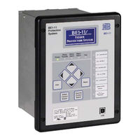
Basler BE1-11g Quick Start Manual (24 pages)
BE1-11 series Protection Systems
Brand:
Basler
| Category:
Protection Device
| Size: 1 MB
Table of Contents
Table of Contents
5
Quick Start Guide
7
Maintenance
7
Storage
7
Install Bestcomsplus® Software
7
Power up and Activate the BE1-11 Plug-In
8
USB Connection
8
Apply Operating Power
8
Start Bestcomsplus® and Activate BE1-11 Plugin
10
Programming the BE1-11
12
Introduction to Bestcomsplus
12
Summary Screens
13
Programming Example
14
Revision History
21
Advertisement
Related Products
Basler BE1-27/59
Basler BE1-51
Basler BE1-32 O/U
Basler BE1-32
Basler BE1-24
Basler BE1-81O/U
Basler BE1-50/51B-223
Basler BE1-50/51B-226
Basler BE1-50/51M-104 Series
Basler BE1-50/51M-204 Series
Basler Categories
Relays
Digital Camera
Controller
Security Camera
Protection Device
More Basler Manuals
Login
Sign In
OR
Sign in with Facebook
Sign in with Google
Upload manual
Upload from disk
Upload from URL