Sign In
Upload
Manuals
Brands
Basler Manuals
Relays
BE1-81O/U
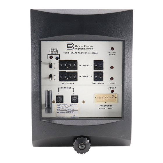
Basler BE1-81O/U Digital Frequency Relay Manuals
Manuals and User Guides for Basler BE1-81O/U Digital Frequency Relay. We have
2
Basler BE1-81O/U Digital Frequency Relay manuals available for free PDF download: Instruction Manual
Basler BE1-81O/U Instruction Manual (49 pages)
DIGITAL FREQUENCY RELAY
Brand:
Basler
| Category:
Relays
| Size: 1 MB
Table of Contents
Table of Contents
4
Applications
6
Description
6
Section 1 • General Information
6
List of Illustrations
7
Model and Style Number
7
Style Number Example
7
Figure 1-1. Style Number Identification Chart
7
Specifications
8
Undervoltage Inhibit
9
Figure 1-2. Inverse Time Overfrequency Characteristic Curves
11
Figure 1-3. Inverse Time Underfrequency Characteristic Curves
12
Section 2 HUMAN MACHINE INTERFACE (Controls and Indicators)
13
Figure 2-1. Location of Controls and Indicators
14
Figure 2-2. Location of Controls and Indicators, S1 Case
15
Figure 2-3. Definite Time Board Switch S7
16
Figure 3-1. Bandpass Filter Characteristics
17
Section 3 FUNCTIONAL DESCRIPTION
17
Figure 3-2. BE1-81O/U Functional Block Diagram
18
Figure 3-3. Location of Assemblies (Typical M1 Case)
19
Zero-Crossing Logic
20
Crystal Oscillator
20
Period Clock Generator
20
Minimum Period Difference Logic
20
Figure 3-4. Location of Assemblies (Typical S1 Case)
20
Maximum Period Difference Logic
21
Measured Frequency Converter
21
Frequency Comparator Logic
21
Definite Time Delay Logic
21
Inverse Time Delay Logic
21
Relay Output
22
Auxiliary Relay Output
22
Target
22
Power Supply
22
Power Supply Status Output
22
Section 4 • Installation
23
General
23
Relay Operating Precautions
23
Dielectric Test
23
Mounting
23
Connections
23
Figure 4-1. S1 Case, Panel Drilling Diagram, Semi-Flush Mounting
24
Figure 4-2. S1 Case, Outline Dimensions, Front View
25
Figure 4-3. S1 Case, Double-Ended, Semi-Flush Mounting, Side View
26
Figure 4-4. S1 Case, Single-Ended, Semi-Flush Mounting, Side View
27
Figure 4-6. S1 Case, Double-Ended, Projection Mounting, Panel Drilling Diagram
29
Figure 4-7. S1 Case, Double-Ended, Projection Mounting, Rear View
30
Figure 4-8. S1 Case, Double-Ended, Projection Mounting, Side View
31
Figure 4-9. M1 Case, Semi-Flush Mounting, Panel Drilling Diagram
32
Figure 4-10. M1 Case, Outline Dimensions, Front View
33
Figure 4-11. M1 Case, Double-Ended, Semi-Flush Mounting, Side View
34
Figure 4-12. M1 Case, Single-Ended, Semi-Flush Mounting, Sideview
35
Figure 4-13. M1 Case, Single-Ended, Projection Mounting, Panel Drilling Diagram
36
Figure 4-15. M1 Case, Double-Ended, Projection Mounting, Panel Drilling Diagram
38
Figure 4-16. M1 Case, Double-Ended, Projection Mounting, Outline Dimensions
39
Figure 4-17. M1 Case, Double-Ended, Projection Mounting, Side View
40
Figure 4-18. Internal Connections
41
Figure 4-19. DC Connections
42
Figure 4-20. AC Sensing Connections
42
Section 5 • Tests and Adjustments
43
General
43
Required Test Equipment
43
Operational Test
43
High and Low Frequency Pickup
43
Frequency Selector Settings
44
Figure 5-1. Test Setup Diagram
44
Definite TIME DELAY (Option E1)
45
Definite TIME DELAY (Option E2)
45
Inverse TIME DELAY (Option D1)
46
Undervoltage Inhibit
47
SETPOINT 2, 3, and 4 Performance Tests
47
Section 6 • Maintenance
48
General
48
In-House Repair
48
Storage
48
Test Plug
48
Manual Change Information
49
Advertisement
Basler BE1-81O/U Instruction Manual (47 pages)
DIGITAL FREQUENCY RELAY
Brand:
Basler
| Category:
Relays
| Size: 0 MB
Table of Contents
Table of Contents
7
Section 1 • General Information
9
Introduction
9
Features
9
Frequency Setpoints
9
Time Delays
9
Undervoltage Inhibit
9
Targets
9
Operation
9
Style Number
9
Specifications
11
Sensing Input
11
Operating Power Input
11
Relay Outputs
11
Output Contacts
11
Target Indicators (Optional)
11
Frequency Setpoint
12
Time Delay
12
Undervoltage Inhibit
12
Type Tests
12
Temperature Ratings
13
UL Recognized
13
Gost-R
13
Case Size
13
Weight
13
Section 2 • Controls and Indicators
17
Introduction
17
Front Panel
17
Circuit Board
18
Multiplier Settings
19
Cycles/Seconds Settings
19
Section 3 • Functional Description
21
Introduction
21
Functional Description
21
Input Signal
21
Undervoltage Inhibit
21
Zero Crossing Logic
21
Crystal Oscillator
21
Period Clock Generator
21
Minimum Period Difference Logic
21
Maximum Period Difference Logic
23
Measured Frequency Converter
23
Frequency Comparator Logic
23
Definite Time Delay Logic
23
Relay Outputs
25
Auxiliary Relay Outputs
25
Power Supply
25
Power Supply Status Output
25
Target Indicators
25
Section 4 • Installation
27
Introduction
27
Operating Precautions
27
Mounting
27
Connections
41
Maintenance
42
Storage
42
Section 5 • Testing
43
Introduction
43
Test Equipment
43
Operational Test
43
Frequency Selector Settings
44
Definite Time Delay - Cycles
45
Definite Time Delay - Seconds
45
Undervoltage Inhibit
45
Setpoint 2, 3, and 4 Testing
46
Advertisement
Related Products
Basler BE1-87T
Basler BE1-87B
Basler BE1-81
Basler BE1-51/27R
Basler BE1-24
Basler BE1-79A
Basler BE1-25/79TR
Basler BE1-50/51M-100 Series
Basler BE1-50/51M-200 Series
Basler BE1-50B-230
Basler Categories
Relays
Digital Camera
Controller
Security Camera
Protection Device
More Basler Manuals
Login
Sign In
OR
Sign in with Facebook
Sign in with Google
Upload manual
Upload from disk
Upload from URL