Sign In
Upload
Manuals
Brands
Allen-Bradley Manuals
Controller
Micro800
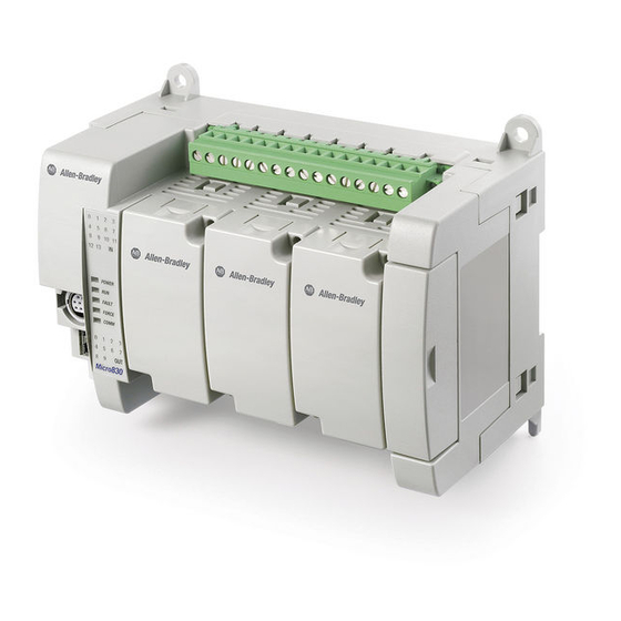
User Manuals: Allen-Bradley Micro800 PLC Modules
Manuals and User Guides for Allen-Bradley Micro800 PLC Modules. We have
6
Allen-Bradley Micro800 PLC Modules manuals available for free PDF download: General Instructions Manual, User Manual, Installation Instructions Manual
Allen-Bradley Micro800 General Instructions Manual (652 pages)
Programmable Controllers
Brand:
Allen-Bradley
| Category:
Controller
| Size: 12 MB
Table of Contents
Table of Contents
3
In this Manual
13
Preface
13
Supported Controllers
13
Additional Resources
14
Chapter 1 Instruction Blocks
15
Finding Information about Instructions and Ladder Elements
15
Functions
16
Operators
16
Function Blocks
18
Instruction Set in Alphabetical Order
19
Instruction Set by Type and Function
23
Chapter 2
29
Ladder Diagram (LD) Language
29
LD Program
29
LD Program Development Environment
30
Ladder Diagram (LD) Elements
32
Chapter 3
35
Instruction Block (LD)
35
Coil
39
Contact
44
Return
48
Jump
49
Instruction Blocks in LD Programs
49
Working in the LD Language Editor
50
Ladder Diagram (LD) Program Examples
52
Example: R_TRIG Function Block
52
Example: Comparing Real Values Using Subtraction (-) ABS, and Less than (<)
53
LD Keyboard Shortcuts
54
Chapter 4
57
Alarm Instruction
58
Lim_Alrm
58
Abs
62
Chapter 5
62
Acos
64
Acos_Lreal
66
Addition
68
Asin
69
Asin_Lreal
71
Atan
73
Atan_Lreal
75
Cos
77
Cos_Lreal
79
Division
81
Expt
82
Log
84
Mod
86
Mov
88
Multiplication
89
Neg
90
Pow
91
Rand
93
Sin
95
Sin_Lreal
97
Sqrt
99
Subtraction
101
Tan
102
Tan_Lreal
104
Trunc
106
ASCII Serial Port Instructions
109
Chapter 6
109
Abl
110
Acb
112
Acl
114
Ahl
116
Ard
118
Arl
121
Awa
123
Awt
125
Rockwell Automation Publication 2080-RM001D-EN-E - February
126
ASCII Parameter Details
127
ABL Error Codes
127
ABLACB Data Type
128
ACL Data Type
128
AHL Channelsts Data Type
129
AHLI Data Type
129
ARDARL Data Type
130
AWAAWT Data Type
130
Chapter 7
131
And_Mask
132
Binary Instructions
132
Not_Mask
134
Or_Mask
136
Rol
138
Ror
140
Shl
142
Shr
144
Xor_Mask
146
Boolean Instructions
149
Chapter 8
149
F_Trig
150
R_Trig
152
And
157
Xor
158
Not
159
Ttable
162
TTABLE Input Combinations
163
Mux8B
166
Mux4B
170
Chapter 9
173
Msg_Cipgeneric
174
CIPAPPCFG Data Type
176
CIPCONTROLCFG Data Type
177
CIPSTATUS Data Type
178
CIPTARGETCFG Data Type
180
Msg_Cipsymbolic
184
CIPSYMBOLICCFG Data Type
187
CIPAPPCFG Data Type
189
CIPCONTROLCFG Data Type
190
CIPSTATUS Data Type
191
CIPTARGETCFG Data Type
193
Supported Data Packet Size for CIP Serial Function
196
Msg_Modbus
197
Modbus Error Codes
199
MODBUSLOCPARA Data Type
200
Message Execution Process (Rung = TRUE)
202
MODBUSTARPARA Data Type
204
Msg_Modbus2
205
Modbus2 Error Codes
208
MODBUS2LOCPARA Data Type
209
MODBUS2TARPARA Data Type
210
Message Execution Processes and Timing Diagrams
213
Message Execution Process (General)
214
Message Execution Sequence (General)
215
Message Execution Process (Rung = TRUE)
215
Message Execution Timing Diagram (Rung = TRUE)
217
Message Execution Process (Rung = FALSE)
218
Message Execution Timing Diagram (Rung = FALSE)
220
Message Execution Process (Error)
221
Message Execution Timing Diagram (Error)
221
Using the Communication (Message) Function Blocks
222
Configuring Object Data Values for Explicit Messaging (MSG_CIPGENERIC)
222
Example: How to Create a MSG_CIPGENERIC Messaging Program to Read Data from a Controller
225
Example: How to Create a MSG_CIPSYMBOLIC Messaging Program to Write a Value to a Variable
239
Example: How to Configure Modbus Communication to Read from and Write to a Drive
251
Communication Protocol Support
257
Embedded Communication Channels
258
Rockwell Automation Publication 2080-RM001D-EN-E - February
259
Compare Instructions Equal
260
Chapter 10 Equal ..................................................................................................................... 260
262
Greater than
262
Greater than or Equal
263
Less than
264
Less than or Equal
265
Not Equal
266
Counter Instructions
267
Ctd
268
Ctu
270
Ctud
273
Chapter 11
267
Chapter 12
277
Any_To_Bool
278
Any_To_Byte
279
Any_To_Date
280
Any_To_Dint
281
Any_To_Dword
282
Any_To_Int
283
Any_To_Lint
284
Any_To_Lreal
285
Any_To_Lword
286
Any_To_Real
287
Any_To_Sint
288
Any_To_String
289
Any_To_Time
290
Any_To_Udint
291
Any_To_Uint
292
Any_To_Ulint
293
Any_To_Usint
294
Any_To_Word
295
Data Manipulation Instructions
297
Average
298
Chapter 13
298
Cop
300
COP Operation Status Values
304
Copying to a Different Data Type
304
Min
305
Max
307
High-Speed Counter (HSC) What Is a High-Speed Counter
309
Chapter 14 What Is a High-Speed Counter? ...................................................................... 309
311
Hsc
311
Hsccmd Values
313
HSCAPP Data Type
314
HSCSTS Data Type
320
PLS Data Type
330
HSC Status Codes (STS)
331
Hsc_Set_Sts
332
Using the High-Speed Counter Instructions
335
Updating HSC Application Data
335
High-Speed Counter (HSC) User Interrupt Dialog Box
336
Configuring High-Speed Counter (HSC) User Interrupts
337
Add and Configure a High-Speed Counter (HSC) User Interrupt
337
Configuring a Programmable Limit Switch (PLS)
341
Example: How to Create a High-Speed Counter (HSC) Program
342
Add a Programmable Limit Switch (PLS) Function
353
Example: Programmable Limit Switch (PLS) Enabled
355
Chapter 15
357
Lcd
358
Lcd_Bklt_Rem
361
LCD_BKLT_REM Status Codes
363
Lcd_Rem
364
LCD_REM Status Codes
368
Rhc
369
Rpc
371
Dlg
373
DLG Status Codes
375
DLG Error Codes
375
IIM
376
Rockwell Automation Publication 2080-RM001D-EN-E - February
376
IIM Status Codes
378
Iom
379
IOM Status Codes
381
Key_Read
382
Key_Read_Rem
386
KEY_READ_REM Operation
387
KEY_READ_REM Status Codes
388
Keydata Bitfields Table
389
Mm_Info
390
MMINFO Data Type
392
Plugin_Info
393
Plugin_Read
396
PLUGIN_READ Status Codes
398
Plugin_Reset
399
Plugin_Write
401
Rcp
403
RCP Status Codes
405
RCP Error Codes
406
Rtc_Read
407
RTC Data Type
409
Rtc_Set
410
RTC Set Status Values
412
Sys_Info
413
SYS_INFO Data Type
415
Trimpot_Read
416
Trimpot ID Definition
418
Trimpot Operation Status Values
418
Chapter 16
419
Interrupt Instructions
420
Stis
420
Uic
422
Uid
424
Uie
426
Uif
428
Motion Control Instructions General Rules for Motion Control Function Blocks
432
Chapter 17 General Rules for Motion Control Function Blocks ........................................ 432
435
Motion Control Function Block Parameter Details
435
Motion Control Axis States
435
Motion Control Function Block Parameter Numbers
438
Motion Control Function Block Error Ids
440
Axis Error Scenarios
442
AXIS_REF Data Type
443
FB_AXIS_REF Data Type
443
Axis Variables
445
Mc_Aborttrigger
446
Mc_Halt
449
Mc_Home
453
Homing Modes
457
Mc_Moveabsolute
460
Mc_Moverelative
463
Mc_Movevelocity
468
Mc_Power
473
Mc_Readactualposition
477
Mc_Readactualvelocity
481
Mc_Readaxiserror
485
Axiserrorid Error Codes
489
Mc_Readboolparameter
491
Mc_Readparameter
495
Mc_Readstatus
498
Mc_Reset
503
Mc_Setposition
506
Mc_Stop
510
Mc_Touchprobe
514
Motion Fixed Input/Output
518
Mc_Writeboolparameter
519
Mc_Writeparameter
523
Rockwell Automation Publication 2080-RM001D-EN-E - February
524
Chapter 18
528
Derivate
528
Process Control Instructions
528
Hyster
530
Integral
532
Pwm
539
PWM Status Codes
542
Scaler
543
Stackint
546
Tnd
549
Limit
551
Program Control Instruction
555
Sus
556
Chapter 19
555
Chapter 20
559
Derivative (PID) Instruction How the Ipidcontroller Function Block Implements PID Control
560
Proportional Integral
560
Ipidcontroller
562
GAIN_PID Data Type
566
At_Param Data Type
566
Ipidcontroller Function Block Operation
567
Using the Proportional Integral Derivative Instruction
569
Using Auto-Tune with the Ipidcontroller Function Block
569
Example: Ipidcontroller with Auto-Tune
576
Example: How to Create a Feedback Loop for the Manipulated Value
578
Example: How to Add a UDFB to a PID Program
579
Example: How to Create an Ipidcontroller Program to Control Temperature
580
Example: How to Create an Ipidcontroller Program to Control Water Supply Level
582
Chapter 21
587
Rtc_Read
588
Rtc_Set
590
RTC Data Type
592
RTC Set Status Values
592
Ascii
594
Chapter 22
594
Char
596
Delete
598
Find
600
Insert
602
Left
604
MID
606
Mlen
608
Right
610
Replace
613
Timer Instructions
617
Tof
619
Ton
622
Tonoff
625
Rto
631
Doy
634
DOYDATA Data Type
636
Tdf
637
Tow
639
TOWDATA Data Type
642
Chapter 23
617
Index
643
Rockwell Automation Publication 2080-RM001D-EN-E - February
643
Advertisement
Allen-Bradley Micro800 User Manual (124 pages)
Plug-in Modules
Brand:
Allen-Bradley
| Category:
Control Unit
| Size: 6 MB
Table of Contents
Important User Information
2
Who Should Use this Manual
3
Purpose of this Manual
3
Conformal Coated Catalogs
3
Additional Resources
3
Table of Contents
7
Digital Plug-Ins
13
Iq4Ov4, 2080-Ob4, 2080-Ov4
13
AC/DC Relay Output Module - 2080-OW4I
13
Analog Plug-Ins
13
2080-If4, 2080-Of2
13
Specialty Plug-Ins
13
Rtd2
13
And 2080-MEMBAK-RTC2
13
Six-Channel Trimpot - 2080-TRIMPOT6
14
High Speed Counter - 2080-MOT-HSC
14
Communication Plug-Ins
14
RS232/RS485 Isolated Serial Port - 2080-SERIALISOL
14
Devicenet Scanner - 2080-DNET20
15
Hardware Features
17
Insert Module into Controller
17
Wiring
18
Wiring Considerations and Applications for 2080-TC2
23
Type of CJC Sensor
23
Wire the CJC Thermistor on the 2080-TC2 Module
23
Wiring Considerations and Applications for 2080-RTD2
25
Two-Wire and Three-Wire Wiring
25
Wire the RTD Sensors
25
Wire the RTD Module and RTD Sensor in the Field
26
Wiring Applications for 2080-MOT-HSC
27
Thermocouple Module
29
Thermocouple Sensor Types and Ranges
29
RTD Module
30
RTD Sensor Types and Ranges
30
Data Maps
32
Temperature Conversion - Data to Degree Celsius (°C)
33
Overview
35
Differences between Embedded HSC and Plug-In Module
36
Counter Specifications
36
Number of Counters: 1 to 2
37
Up Counter
38
Counter with External Direction
38
Understanding Rates
44
User Defined Function Blocks
46
Ra_Hscplugin
46
Use the 2080-MOT-HSC Module
49
Overview
51
Status Indicators
51
Network Configuration
52
Network Wiring
52
Devicenet Switches
53
Power Supply
54
User Defined Function Blocks
57
Ra_Dnet_Master
57
Ra_Dnet_Node_Status
58
Ra_Dnet_Ldx_Discrete
59
Ra_Dnet_Ldx_Analog
60
Ra_Dnet_Ldx_Tc_Rtd
61
Ra_Pf_Dnet_Standard
62
Ra_Pf_Dnet_Multidrive
63
Ra_Dnet_Overload
65
Ra_Dnet_Generic
65
Through
68
Error Codes
69
Use the 2080-DNET20 Plug-In
70
Digital Plug-In Modules
71
Analog Plug-In Modules
77
Specialty Plug-In Modules
81
Communication Plug-In Modules
89
Add and Configure Plug-Ins in Connected Components Workbench
93
Browse Your 2080-DNET20 Plug-In Using Rslinx
95
Browse Using the Devicenet Network
96
Browse Using the Micro800 Pass through
97
Flash Upgrade Your
98
2080-DNET20 Plug-In Firmware
98
Quickstart Project for 2080-DNET20 Plug-In
102
Setup and Wiring
103
Configuration
104
Build and Download
106
Execute Program
107
Quickstart Projects for 2080-MOT-HSC Plug-In
107
Setup and Wiring
108
Configuration for UDFB 1: Ra_Hscplugin
109
Build and Download
110
Execute the Function Block
110
Configuration for UDFB 2: Ra_Encoderfdbk
111
Build and Download
112
Execute the Function Block
113
Configuration for HSC UDFB 3: Ra_Servofdbk
114
Build and Download
115
Execute the Function Block
116
Troubleshooting
119
Error Codes for Micro800 Plug-Ins
119
Calling Rockwell Automation for Assistance
120
Allen-Bradley Micro800 User Manual (78 pages)
Discrete and Analog Expansion I/O
Brand:
Allen-Bradley
| Category:
Control Systems
| Size: 2 MB
Table of Contents
Additional Resources
3
Purpose of this Manual
3
Who Should Use this Manual
3
Table of Contents
7
Chapter 1
9
Micro800 Expansion I/O Modules
9
Hardware Features
10
Summary
12
Overview
13
Chapter 2 Discrete Expansion I/O Features
13
Discrete Input
13
Discrete Output
14
Analog Expansion I/O Features
14
Analog Input and Output
15
Specialty Module 2085-IRT4 Temperature Input Module
19
Summary
22
Chapter 3 Input/Output Wiring
23
Wiring Options for the 2085-IQ32T Module
29
Summary
32
Chapter 4 Mount the Module
33
Module Spacing
33
DIN Rail Mounting
34
Panel Mounting
35
System Assembly
35
Summary
36
Overview
37
Chapter 5
37
Add an Expansion I/O
37
Edit Expansion I/O Configuration
40
Delete and Replace an Expansion I/O Configuration
50
Build, Save, Download a Project with Expansion I/O Configuration
52
Summary
52
Appendix A
53
Discrete Expansion I/O
53
Analog Expansion I/O
58
Specialty Expansion I/O
60
Discrete I/O Data Mapping
65
Appendix B Analog I/O Data Mapping
66
Specialty I/O Data Mapping
69
Calibration of Analog Modules
71
Specifications
71
Advertisement
Allen-Bradley Micro800 Installation Instructions Manual (24 pages)
Remote LCD
Brand:
Allen-Bradley
| Category:
Controller
| Size: 1 MB
Table of Contents
Table of Contents
1
Important User Information
2
North American Hazardous Location Approval
4
Additional Resources
6
Overview
7
Install the Micro800 Remote LCD
9
Mount the Module
10
Connect Power
14
RS232 Port
16
USB Port
16
Specifications
18
Allen-Bradley Micro800 Installation Instructions Manual (16 pages)
Programmable Controller External AC Power Supply
Brand:
Allen-Bradley
| Category:
Controller
| Size: 0 MB
Table of Contents
Table of Contents
1
Important User Information
2
Overview
7
Connect the Power Supply
8
Wire the Module
9
Specifications
10
Allen-Bradley Micro800 Installation Instructions Manual (12 pages)
4-channel and 8-channel Analog Voltage/Current Input and Output Modules
Brand:
Allen-Bradley
| Category:
I/O Systems
| Size: 1 MB
Table of Contents
Table of Contents
1
Important User Information
2
Additional Resources
5
Overview
5
Module Description
6
Mount the Module
6
Wire the Modules
9
Specifications
9
Advertisement
Related Products
Allen-Bradley Micro850 series
Allen-Bradley Micro830
Allen-Bradley Micro820
Allen-Bradley Micro810
Allen-Bradley Micro870
Allen-Bradley Mini-PLC-2/15
Allen-Bradley Guard Master MSR22LM
Allen-Bradley MicroLogix 1200 RTD/Resistance
Allen-Bradley GuardShield Micro 400
Allen-Bradley Mini-PLC Mini-PLC-2/16
Allen-Bradley Categories
Control Unit
Controller
I/O Systems
Power Supply
Switch
More Allen-Bradley Manuals
Login
Sign In
OR
Sign in with Facebook
Sign in with Google
Upload manual
Upload from disk
Upload from URL