Table of Contents
Advertisement
Quick Links
Advertisement
Table of Contents

Related Manuals for SoundCraft Vi5000


Summary of Contents for SoundCraft Vi5000
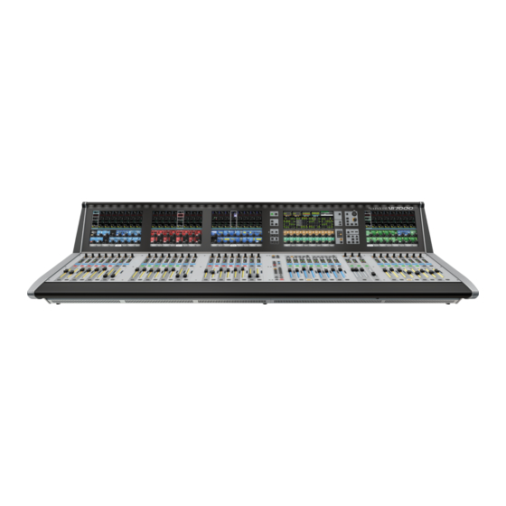
- Page 1 User Guide v1.6 ®...
-
Page 2: Important Information
Soundcraft is a trading division of Harman International Industries Ltd. Information in this manual is subject to change without notice and does not represent a commitment on the part of the vendor. Soundcraft shall not be liable for any loss or damage whatsoever arising from the use of information or any error contained in this manual. No part of this... -
Page 3: Table Of Contents
® Vi5000/7000 User Manual CONTENTS 1.0 INTRODUCTION 12.0: METERING 1.1: Saftey Notices & Warnings 12.1: Inputs 1.2: Product Warranty 12.2: Busses 13.0: EDIT SYSTEM 2.0: SPECIFICATIONS (COPY, PASTE, AND LIBRARY) 2.1: Console block diagram 13.1: Copy, Paste, Undo 13.2: Library Basics 13.3: Library File Screen... -
Page 4: Introduction
By optimising the density of layers can cause all kinds of headaches. Soundcraft® FaderGlow solves the problem associated with multiple faders and controls on the operating surface, the fader layers. -
Page 5: Safety Notices
Ensure that these colour codings are followed carefully in the event of the plug being changed. The internal power supply unit contains no user serviceable parts. Refer all servicing to a qualified service engineer, through the appropriate Soundcraft dealer. 1.1: SAFETY NOTICES... - Page 6 • It is recommended that all maintenance and service on the product should be carried out by Sound- craft or its authorised agents. Soundcraft cannot accept any liability whatsoever for any loss or damage caused by service, maintenance or repair by unauthorised personnel.
- Page 7 Equipment or the defective component should be returned to the Dealer or to Soundcraft and subject to the following conditions the Dealer or Soundcraft will repair or replace the defec- tive components. Any components replaced will become the property of Soundcraft.
-
Page 8: Specifications
Line Outputs: +22dBu max (104°F) Nominal Operating Level: +4dBu (-18dBFS) Storage Temperature Range: -20°C to 60°C Input & Output Impedances Mic Inputs: 10kΩ (-4°F – 140°F) E & OE. Soundcraft reserves the right to change specifications without notice. 2.0: SPECIFICATIONS... -
Page 9: Hardware Overview
4.0: HARDWARE HARDWARE The Vi5000 and Vi7000 systems feature Local Rack and Stagebox inputs and outputs (I/O). The Local Rack houses the system DSP (audio processing), data connections, and some direct digital and analogue audio connections. It is designed to remain local to the control surface and connects via the supplied Console-To-Local-Rack cable. - Page 10 ® Vi5000/7000 User Manual 4.0: HARDWARE OVERVIEW HARDWARE OVERVIEW 4.0: HARDWARE OVERVIEW...
- Page 11 ® Vi5000/7000 User Manual 4.1: SURFACE CONNECTIONS HARDWARE > CONTROL SURFACE CONNECTIONS The rear of the control surface has essential audio connections, data connection to the Local Rack, MIDI, USB, and HiQnet (Ethernet) connections, as well as the dual-redundant power supply connections and switches.
- Page 12 See section 18 for more detail. This is an XLR-Housed EtherCon connector. This port is also used for connecting a wireless access point for iPad remote control using the ViSi Remote app, and for connecting the Soundcraft Realtime Rack Plug-in engine for storage and recall of plug-in snapshots. Connection for USB memory devices and/or USB keyboard USB memory sticks can be used to save and load console Snapshot, show, and library data.
- Page 13 ® Vi5000/7000 User Manual 4.2: LOCAL RACK HARDWARE > LOCAL RACK The rack consists of a 6U processing and I/O unit, developed by Studer, called the SCore. Below this is a 3U low- noise cooling fan unit. There is also an Active Breakout Unit, which provides direct audio connections for local use and for connection to the Control Surface, and a another Breakout Panel for convenient MADI connections for Stageboxes.
- Page 14 To gain access to the adjustment trimmer, remove the small 2-part plastic blanking plug located to the left of the fan filter grille. Insert a small screwdriver into the hole to adjust: turn anticlockwise to reduce the speed. Contact Soundcraft for advice before changing fan speed if unsure. Ensure fan units on Local Rack and Stagebox are connected and operational.
- Page 15 ® Vi5000/7000 User Manual 4.2.2: SCore FRONT PANEL HARDWARE > LOCAL RACK > SCore FRONT PANEL The status LEDs on the front panel of the SCore unit give an at-a-glance indication that the Local Rack is functioning correctly, or that an error condition has occurred. An illuminated green LED indicates the presence of a card, an illuminated red LED warns of a card error.
- Page 16 ® Vi5000/7000 User Manual 4.2.3: SCore CARD FRAME HARDWARE > LOCAL RACK > SCore CARD FRAME The rear panel of the SCore shows the Score Card Frame. Your console’s Card Frame will be populated according to your own specification. The diagram shows a 96kHz-capable system with four MADI cards installed. A 48kHz-only system has five DSP cards installed in the top section, with three additional ‘blank’...
- Page 17 ® Vi5000/7000 User Manual 4.2.3: SCore CARD FRAME HARDWARE > LOCAL RACK > SCore CARD FRAME FX Card Provides the additional DSP and algorithms required to run the eight Lexicon digital FX processors. Audio Clock Card Provides clock connection to external equipment, both in and out. The wordclock input options are Video clock, stand- ard wordclock or AES/EBU sync clock.
- Page 18 ® Vi5000/7000 User Manual 4.2.4: LOCAL RACK CONNECTIONS HARDWARE > LOCAL RACK > CONNECTIONS The SCore Rack Frame cards should be connected correctly before operating the system, using the supplied cables. 1) Connect the DSP cards 1 and 2 (left-most DSP cards in frame) to the HD cards as shown.
- Page 19 ® Vi5000/7000 User Manual 4.2.4: LOCAL RACK CONNECTIONS HARDWARE > LOCAL RACK > CONNECTIONS 4.2.4: SCore CONNECTIONS...
- Page 20 ® Vi5000/7000 User Manual 4.3: Vi STAGE BOX HARDWARE > Vi STAGE BOX The 9U Vi Stagebox houses 64 mic/line inputs and 32 analogue line outputs. Mic/line amp gain, 48 V phantom power and 100 Hz lo-cut filter before the A-D converters can all be controlled remotely from the desk. The Stagebox is availa- ble in Standard 64/32 configuration, or can be reconfigured as part-fitted or with alternative cards as required.
- Page 21 ® Vi5000/7000 User Manual 4.5: DIMENSIONS / DRAWINGS HARDWARE > DIMENSIONS / DRAWINGS 1436.9mm 725.1mm 1731.9mm 4.5: DIMENSION / DRAWINGS...
-
Page 23: Operations Overview
5.0: OPERATIONS OVERVIEW OPERATIONS OVERVIEW The illustrations in this manual show the Vi5000 console. The Vi7000 has an extra eight-wide Inputs Bay. Where relevant, the text / illustrations will note operational differences between the Vi5000 and the Vi7000 models. 5.0: OPERATIONS OVERVIEW... - Page 24 ® Vi5000/7000 User Manual 5.1: CONVENTIONS AND COLOURS OPS OVERVIEW > CONVENTIONS & COLOURS This manual, and the console uses certain conventions to make things significantly easier for the user. This includes the unique FaderGlow technology that can dynamically colour code console faders depending on their current assignment.
-
Page 25: Vistonics
OPS OVERVIEW > VISTONICS Vistonics II is a unique control and display technology derived from the Studer Vistonics technology and exclusive to Soundcraft. The console uses Vistonics II as a core technology for console operation because of its significant user-interface benefits. - Page 26 ® Vi5000/7000 User Manual 5.2: VISTONICS OPS OVERVIEW > VISTONICS Buttons On/Off If a function is assigned to a button it is displayed as shown. The 'active' state shows the button highlighted in a lighter colour. Open Touch Page Open a configuration window such as a labelling or patching screen If the button can open a configuration page in the Touch area it shows a '+' sign on the button.
-
Page 27: Console Bays
OPS OVERVIEW > CONSOLE BAYS The Vi5000 is divided into four main bays, and the Vi7000 is divided into five. Both have a single Master Bay, a right-hand Input Bay (which has additional fast-assign capability - see Section 5.3.1), and several left-hand Input Bays (two for the Vi5000 and three for the Vi7000). - Page 28 ® Vi5000/7000 User Manual 5.3.1: INPUT BAY 3/4 OPS OVERVIEW > INPUT BAY 3/4 NAVIGATION The Master Bay touch screen meters can be used as a navigation device - simply touch a block of eight meters and those channels (both inputs and outputs) are mapped to the right-hand input bay. This is excellent for fast access and for dual operator scenarios.
-
Page 29: Faderglow
5.4: FADERGLOW OPS OVERVIEW > FADERGLOW™ Soundcraft FaderGlow™ (Pat. Pend.) is a unique feature that gives the user an additional level of status indication, and can significantly reduce operating errors. On the console, several different functions can be assigned to a particular fader, it can therefore be easy to forget which function is currently being controlled, especially when grabbing a fader in a hurry. - Page 30 ® Vi5000/7000 User Manual 5.5: BUTTONS OVERVIEW OPS OVERVIEW > CONSOLE BUTTONS There are a wide variety of button groups on the console. Below are described all button groups and selected individu- al buttons. Please refer to the relevant reference section for detailed information on the operation of all buttons.
- Page 31 ® Vi5000/7000 User Manual 5.5: BUTTONS OVERVIEW OPS OVERVIEW > CONSOLE BUTTONS Input Channel VISTONICS Group The input channel VISTONICS control buttons provide convenient ways of assigning bus master functions to the input channel VST encoders, such as selections for individual bus ‘tap’...
- Page 32 ® Vi5000/7000 User Manual 5.5: BUTTONS OVERVIEW OPS OVERVIEW > CONSOLE BUTTONS Input Fader Pages These buttons control navigation through five basic input channel Pages/Layers, including the ‘All Busses’ view, plus five user-definable pages. These buttons only affect the input channel bays.
- Page 33 ® Vi5000/7000 User Manual 5.5: BUTTONS OVERVIEW OPS OVERVIEW > CONSOLE BUTTONS [SETUP] Buttons [SETUP] buttons open the relevant setup screen in the Master Bay Vistonics screen. While a setup screen is active, pressing the [SETUP] button again will close that setup screen. For more informa- tion see the chapter relevant to each [SETUP] button.
- Page 34 ® Vi5000/7000 User Manual 5.5: BUTTONS OVERVIEW OPS OVERVIEW > CONSOLE BUTTONS Lower [FLW] Button Input faders follow master bus selection. The fader FOLLOW OUTPUT SOLO [FLW] button located near the bottom of the Master Bay buttons strip (not the VISTONICS encoder [FLW] buttons) causes the input faders to become contributions to an output bus when its [SOLO/SEL] button is pressed (often known as ‘Sends on Faders mode’).
-
Page 35: Encoders
® Vi5000/7000 User Manual 5.6: ENCODERS OPS OVERVIEW > ENCODERS Each input channel strip contains three encoders: encoder 1 and encoder 2 are located in the VST fields in the lower screen area, while the channel encoder is located at the top of the fader area, and has an LED ring to indicate its parameter state. -
Page 36: Gangs
® Vi5000/7000 User Manual 5.7: GANGS OPS OVERVIEW > GANGS Gang is a very helpful feature to speed up operations that influence functions on multiple input channels, or on output busses, in the same way. Any parameter change on ganged channels will be applied to all other ganged channels as an offset. -
Page 37: Labelling
® Vi5000/7000 User Manual 5.8: LABELLING OPS OVERVIEW > LABELLING The console labelling system is displayed on a touch-screen area whenever the labelling of a channel, output, cue, file, or other named parameter or item is required. For example, you can label an input channel by touching the channel’s input area on the touch screen then pressing the {CH LABEL} button in the VST area. -
Page 38: Input Channel
® Vi5000/7000 User Manual 6.0: INPUT CHANNEL INPUT CHANNEL Bays 1, 2, and 4 of the console (Input Bays 1, 2, and 3) are normally dedicated to controlling input channels. However, other functions can be mapped to these channels, such as the Master Busses, Matrix feeds, Graphic EQ, and so on. - Page 39 ® Vi5000/7000 User Manual 6.1: FADER PAGES INPUT CHANNEL > FADER PAGES This section is used for navigating Fader Pages (or layers). There are four main layers of input channel strips, and a further five user-definable layers available. The [ALL BUSSES] button maps the output busses to the input channel strips, as described further in the Outputs reference section.
- Page 40 ® Vi5000/7000 User Manual 6.1: FADER PAGES INPUT CHANNEL > FADER PAGES Fixed Fader Layers Select four pages/layers of input channel strips. Each button maps Pages of 24 (Vi 500) or 32 (Vi 7000) channels to the three/four input bays, so for the Vi 5000 input fader layer [A] is channels 1-24;...
- Page 41 ® Vi5000/7000 User Manual 6.2: CHANNEL STRIP INPUT CHANNEL > CHANNEL STRIP Input Channel Strip Encoder Rotary control whose function is defined by the input ENCODER MODE buttons. The Default function is control over the channel's analogue input gain. For more information see the Inputs Encoder Mode reference section 6.3...
- Page 42 ® Vi5000/7000 User Manual 6.2: CHANNEL STRIP INPUT CHANNEL > CHANNEL STRIP Input Isolate Used to isolate the channel (and selections) from snapshot recall and (when Global Filtering is active) from Show file loads. See the Snapshot and Global Filtering reference section 14 for more information.
-
Page 43: Channel Fader
® Vi5000/7000 User Manual 6.2: CHANNEL STRIP INPUT CHANNEL > CHANNEL STRIP Mute/VCA Group Indicators Shows the Mute or VCA Groups that is channel belongs to. The actual target of these LEDs (Mutes, VCAs 1-8, or VCAs 9-16) is determined by the DISPLAY buttons in the MUTE &... -
Page 44: Encoder Mode
® Vi5000/7000 User Manual 6.3: ENCODER MODE INPUT CHANNEL > ENCODER MODE These buttons determine the function of the input channel encoder at the top of the main channel strip. If [ALL BUSSES] is active, the channel encoders are disabled and have no function (the previous function is remem- bered however). - Page 45 ® Vi5000/7000 User Manual 6.3: ENCODER MODE INPUT CHANNEL > ENCODER MODE Mode: Pan Switch the input Encoders to control Pan. Setup Assign input channel parameters to the User 1 and 2 Encoder Mode buttons To assign User 1 and 2 Encoder Modes, press [SETUP], then use the VST encoders to choose from a range of input channel parameters, including EQ and dynamics controls.
-
Page 46: Vst Control
® Vi5000/7000 User Manual 6.4: VST CONTROL INPUT CHANNEL > VISTONICS / VST CONTROL These buttons control the functionality of the input channel VST encoders. You can easily and rapidly assign bus contributions and bus panning to the encoders using this button group. You can assign any group or auxiliary output to the two [USER] rows using the [SETUP] button. - Page 47 ® Vi5000/7000 User Manual 6.4: VST CONTROL INPUT CHANNEL > VISTONICS / VST CONTROL FLW: Encoders Follow Masters Activate the FOLLOW SOLO function for the respective VST encoder rows. Pressing a bus master [SOLO/SEL] button will automatically assign the soloed bus master to this row, overriding the default or the [USER] layer.
- Page 48 ® Vi5000/7000 User Manual 6.5.1: INPUT BLOCK INPUT CHANNEL > TOUCHSCREEN > INPUT BLOCK A mono input channel’s input section touch screen area is at the top of the Vistonics input channel strip area, colour-coded blue. The input section consists of that channel’s input source selection, pre-amp and gain stages control, channel pairing selection for stereo (and other format) channel creation, channel labelling, and channel delay adjustment.
-
Page 49: Input Gain
® Vi5000/7000 User Manual 6.5.1: INPUT BLOCK INPUT CHANNEL > TOUCHSCREEN > INPUT BLOCK Channel Input Select Select either Input 1 or Input 2 as the channel input. The two physical channel inputs are assigned in the IN1 PATCH and IN2 PATCH fields. You can also use the channel strip ‘F’... - Page 50 ® Vi5000/7000 User Manual 6.5.1: INPUT BLOCK INPUT CHANNEL > TOUCHSCREEN > INPUT BLOCK LO CUT Cut-Off Frequency Adjusts the LO CUT cut-off frequency This is part of the digital (post AD) LO CUT / HIGH CUT section and affects all inputs. The affected frequency range is shown graphically in the EQ section of the touch screen.
-
Page 51: Phantom Power
® Vi5000/7000 User Manual 6.5.1: INPUT BLOCK INPUT CHANNEL > TOUCHSCREEN > INPUT BLOCK Phantom Power Apply Phantom Power (+ 48V) to a mic input XLR patched to this input. When phantom power is applied to this channel's input, the '48V' indicated (touch screen input section) is highlighted in red. - Page 52 ® Vi5000/7000 User Manual 6.5.2: EQ BLOCK INPUT CHANNEL > TOUCHSCREEN > EQ BLOCK A mono input channel’s parametric EQ section touch screen area is near the top of the Vistonics input channel strip area, colour-coded red. The EQ section consists of four full-range parametric bands with shelving response available to the LF and HF bands..
-
Page 53: Gain Control
® Vi5000/7000 User Manual 6.5.2: EQ BLOCK INPUT CHANNEL > TOUCHSCREEN > EQ BLOCK EQ Bandwidth / Q Control Adjust the bandwidth or Q (inverse) of the current filter. You can chose whether the adjustment unit is Bandwidth or Q via the main settings screen by hitting the [menu] button. -
Page 54: 3: Dynamics
® Vi5000/7000 User Manual 6.5.3: DYNAMICS INPUT CHANNEL > TOUCHSCREEN > DYNAMICS BLOCK The dynamics section has three main components - The first can either be a GATE or DeEsser section; the other two are a COMPRESSOR and a LIMITER. All three sections can be turned on or off independently. -
Page 55: Gate Attack Time
® Vi5000/7000 User Manual 6.5.3: DYNAMICS INPUT CHANNEL > TOUCHSCREEN > DYNAMICS BLOCK Gate A gate is a threshold driven gain reduction process normally used to reduce the level of, or silence, a signal when it falls below the threshold. The gate section includes an assignable side-chain input with filters, a key signal solo func- tion, and a ducking mode. - Page 56 ® Vi5000/7000 User Manual 6.5.3: DYNAMICS INPUT CHANNEL > TOUCHSCREEN > DYNAMICS BLOCK Gate HOLD function Adjust the Gate Hold Time This is the time an activated gate will remain fully closed, before entering the 'release' phase. Gate Release Time Adjust the Gate Release Time This is the time an activated gate will take to open, from its 'hold' state.
- Page 57 ® Vi5000/7000 User Manual 6.5.3: DYNAMICS INPUT CHANNEL > TOUCHSCREEN > DYNAMICS BLOCK Gate Hi Cut Filter Adjust the cut-off frequency of the gate sidechain hi-cut filter. Together with the gate lo-cut filter, this creates a band-pass filter for side chain control of the gate.
- Page 58 ® Vi5000/7000 User Manual 6.5.3: DYNAMICS INPUT CHANNEL > TOUCHSCREEN > DYNAMICS BLOCK Ess Band Solo Solo the De-esser dynamic filter. Helps pinpoint the 'Ess band' most suited to the current signal. De-Ess Filter Frequency Adjust the centre frequency of the De-ess dynamic filter.
-
Page 59: Compression Ratio
® Vi5000/7000 User Manual 6.5.3: DYNAMICS INPUT CHANNEL > TOUCHSCREEN > DYNAMICS BLOCK Compressor Attack Adjust the compressor attack time. The time it takes for the compression function to reach full attenuation after the threshold has been reached. The slower the attack time, the 'softer' the compression. - Page 60 ® Vi5000/7000 User Manual 6.5.3: DYNAMICS INPUT CHANNEL > TOUCHSCREEN > DYNAMICS BLOCK Limiter In Activate Limiter Include the Limiter in the dynamics section. Limiter Attack Time Adjust the Limiter attack time. The time taken for the limiter to reach full attenuation.
-
Page 61: 4: Busses
® Vi5000/7000 User Manual 6.5.4: BUSSES INPUT CHANNEL > TOUCHSCREEN > BUSSES BLOCK The Busses section of the input channel vistonics touch screen signal path provides access to all Aux and Group contributions in the VST area, The Touch Screen block graphic shows activated Aux levels in orange and group routings in Green. - Page 62 ® Vi5000/7000 User Manual 6.5.4: BUSSES INPUT CHANNEL > TOUCHSCREEN > BUSSES BLOCK Stereo Aux Send Balance Adjust balance of the numbered stereo aux send. The Stereo symbol above the encoder shows that this aux send has been switched to stereo mode. The Pan for the send will become visibke in place of the send level if the global PAN mode switch is activated in the Master Bay..
- Page 63 ® Vi5000/7000 User Manual 6.5.5: OUTPUT INPUT CHANNEL > OUTPUT BLOCK: PAN, INSERT, DIR OUT, DELAY This page contains the output functions of the input channel including the panning, the routing to the mix masters, and the insert point and the direct out parameters. The Pan can work in LR or in LCR mode. In LCR mode an additional width function is available.
-
Page 64: Insert Patch
® Vi5000/7000 User Manual 6.5.5: OUTPUT INPUT CHANNEL > OUTPUT BLOCK: PAN, INSERT, DIR OUT, DELAY LR On Routes the channel signal to the Left and Right masters. Centre On Routes the channel signal to the Centre master bus. Panning Mode Set either LR or LCR Mode. - Page 65 ® Vi5000/7000 User Manual 6.5.5: OUTPUT INPUT CHANNEL > OUTPUT BLOCK: PAN, INSERT, DIR OUT, DELAY Insert Trim Adjust the actual send signal level. Insert On Activate the insert point. Direct Output On Activate the Direct Output for this input channel.
- Page 66 ® Vi5000/7000 User Manual 6.6: BSS DPR 901 ii DEQ INPUT CHANNEL > BSS DPR 901 ii DEQ The console has 16 internal BSS DPR 901 ii Dynamic EQ processors, assignable to the insert points on input chan- nels, output busses, and the Master LCR mix outputs. To assign a 901 EQ, touch the channel’s output block in the Vistonics touch screen, then choose INSERT to access the assignment screen.
- Page 67 ® Vi5000/7000 User Manual 6.6: BSS DPR 901 ii DEQ INPUT CHANNEL > BSS DPR 901 ii DEQ DEQ Sidechain Solo (SC Solo) Listen to just the DEQ sidechain via the Solo buss / monitoring system.. DEQ Q / Bandwidth Adjust the Q or Bandwidth of the filter.
-
Page 68: Outputs
® Vi5000/7000 User Manual 7.0: OUTPUTS OUTPUTS Auxiliaries, Groups, and LCR Mix busses 7.0: OUTPUTS... - Page 69 ® Vi5000/7000 User Manual 7.0: OUTPUTS OUTPUTS There are 32 configurable output busses on the console, plus the Master Left, right, and Centre (LRC) busses. You can choose to assign any of the 32 busses as mono OR stereo Auxiliaries or Groups with full processing. You can create stereo busses with no reduction in the total number of available busses (32 busses are available regardless of whether they are mono or stereo).
-
Page 70: Lcr Mix Masters
® Vi5000/7000 User Manual 7.1: LCR MASTERS OUTPUTS > LCR MIX MASTER BUSSES LRC Mix Outputs The LRC Bus Master faders are located in the MASTERS section in the console Master Bay. These are dedicated faders and controls, and are never used for anything else. - Page 71 ® Vi5000/7000 User Manual 7.1: LCR MASTERS OUTPUTS > LCR MIX MASTER BUSSES Isolate Isolate the LRC Masters from snapshot recall or Show Recall (with global filtering active). See the Snapshots / Global Filtering reference for more detail. Bus On/Off (Mute).
- Page 72 ® Vi5000/7000 User Manual 7.1: LCR MASTERS OUTPUTS > LCR MIX MASTER BUSSES Access L/C/R GEQ Maps the BSS Graphic equaliser for this block to the console faders. See the BSS Graphics Equaliser reference later in this chapter for more Detail.
-
Page 73: Bus Configuration
® Vi5000/7000 User Manual 7.2: BUS CONFIGURATION OUTPUTS > BUS CONFIGURATION To configure the console busses and map the bus masters to the console input channel strips, you simply press the [ALL BUSS] button in the Input Fader Pages controls or assign a bank of eight bus masters to input bay 3 (right hand bay) by touching the relevant metering group in the Master Bay touch screen. - Page 74 ® Vi5000/7000 User Manual 7.2: BUS CONFIGURATION OUTPUTS > BUS CONFIGURATION Bus Type Set the Bus Type for this Bus. Choose from AUX, GRP or MTX with the encoder. If Aux is selected and if the format field is set to stereo then the {CHPAN} field is enabled.
-
Page 75: Bus Master Control
® Vi5000/7000 User Manual 7.3: BUS MASTER CONTROL OUTPUTS > BUS MASTER CONTROL Outputs Controls There are four ways of controlling the console’s bus masters and two ways of accessing the output bus processing and parameters: Master Bay VST Encoders Bus master levels are available on the VST Encoders in the Master Bay, with groups of bus masters selected via the [Page A] and [Page B] Vistonics control buttons. - Page 76 ® Vi5000/7000 User Manual 7.3: BUS MASTER CONTROL OUTPUTS > BUS MASTER CONTROL Master Bay output channel strips Bus masters levels can be mapped to the eight Master Bay faders and associated channel strip controls by selecting Master Bay FADER PAGES buttons [A] (Busses 1-8), [B] (Busses 9-16), [C] (Busses 17-24), and [D] (Busses 25-32).
- Page 77 ® Vi5000/7000 User Manual 7.3.1: MASTER VISTONICS OUTPUTS > MASTERS > VISTONICS With the Bus Master Controls in the VST fields of the Master Bay, a number of primary functions are available. Use the Master Bay VISTONICS button group to control which functions and which masters are available.
-
Page 78: Talkback Assign
® Vi5000/7000 User Manual 7.3.1: MASTER VISTONICS OUTPUTS > MASTERS > VISTONICS Masters Bank Pages Switch between banks of bus masters in the Master Bay Vistonics VST area. Page A assigns bus masters 1-16 to the 16 Vistonics encoders, Page B assigns bus masters 17-32 to these controls. - Page 79 ® Vi5000/7000 User Manual 7.3.2: MASTER CHANNEL OUTPUTS > MASTERS > CHANNEL STRIP The Master Bay channel strips are for output Bus and VCA control, determined by the Master Bay Fader Pages selectors. The [VCA] button maps VCA masters 1-8 to the Master bay faders. Buttons [A] through [D] map busses 1-32 to the Master Bay channel strips in groups of eight.
- Page 80 ® Vi5000/7000 User Manual 7.3.2: MASTER CHANNEL OUTPUTS > MASTERS > CHANNEL STRIP ISO: Isolate Bus Isolate this bus from snapshot recall and Show recall (when Global Filtering is active) See the Snapshot and Global Filtering chapter for more information.
- Page 81 ® Vi5000/7000 User Manual 7.3.3: MASTER PROCESSING OUTPUTS > MASTERS > PROCESS The bus output processing chain has a parametric EQ block, a BSS Graphic Equaliser block (GEQ), a dynamics block, and a Pan/Insert block. You can also label the bus, assign a physical output, and set a delay inside the Pan/Insert block.
- Page 82 ® Vi5000/7000 User Manual 7.3.3: MASTER PROCESSING OUTPUTS > MASTERS > PROCESS Bus Channel Strip EQ Adjust the parametric EQ for this Master. The output bus parametric EQ is the same is used for the input channel EQ. Please see the input channel refer- ence for more detail.
-
Page 83: 4: Graphic Eqs
® Vi5000/7000 User Manual 7.4: GRAPHIC EQ OUTPUTS > GRAPHIC EQUALISERS (GEQ) The console has a total of 35 high-quality BSS Graphic Equalisers (GEQ) - one for each of the 32 assignable Busses, and one for each of the LCR Master outputs. The GEQs are all 30-Band EQs with an adjustable bandwidth control. - Page 84 ® Vi5000/7000 User Manual 7.4: GRAPHIC EQ OUTPUTS > GRAPHIC EQUALISERS (GEQ) Bandwidth Adjust the bandwidth of the 30 GEQ bands. The Bandwidth units can either be Q or Octaves, depending on the {EQ UNIT} setting in the Main Menu (Settings Tab).
- Page 85 (mono or stereo) with full processing including parametric EQ, dynamics, delay, and graphic EQ. Each matrix output is a mix of up to 24 (Vi5000) or 32 (Vi7000) configurable sources that can be signals from busses, channel direct out- puts, or inputs directly from the patching system.
- Page 86 ® Vi5000/7000 User Manual 8.0: MATRIX CONSOLE MATRIX SYSTEM Matrix Source ON Turn on (or off) the corresponding matrix source. Matrix Source Fader Adjust the level of this source as a contribution to the matrix mix. Matrix Source Solo/Sel Cancels the Matrix mapping and returns channels to normal operations.
-
Page 87: Mute & Vca Groups
® Vi5000/7000 User Manual 9.0: MUTE / VCA GROUPS MUTE & VCA GROUPS The console supports up to 4 mute Groups (MG) and 16 primary VCA masters that can include both input and output channels. There is a secondary level of VCA functionality, most useful for monitor engineers, which allows the user to assign up to 16 VCA masters to each auxiliary mix when the auxiliaries are controlled for the channel faders. -
Page 88: Mute Groups
® Vi5000/7000 User Manual 9.1: MUTE GROUPS MUTE & VCA GROUPS > MUTE GROUPS Mute Groups Operation There are four console mute groups, activated with the [1], [2], [3], and [4] buttons in the MUTE & VCA GROUPS but- ton group. Both input and output channels can be assigned to mute groups. -
Page 89: Vca Groups
® Vi5000/7000 User Manual 9.2: VCA GROUPS MUTE & VCA GROUPS > VCA GROUP OPERATION VCA Groups configuration is started by pressing the MUTE & VCA GROUPS [SETUP] button. When you press a VCA Master [SOLO/SEL] button you can assign channels to that VCA group with their individual [SOLO/SEL] buttons, and also access VCA group options - including labelling - in the Master Bay Vistonics. - Page 90 ® Vi5000/7000 User Manual 9.2: VCA GROUPS MUTE & VCA GROUPS > VCA GROUP OPERATION VCA Setup Press the MUTE & VCA GROUPS [SETUP] button, then chose a VCA [SOLO/SEL] to configure that VCA group. The [SETUP] button will glow blue when pressed. The [SOLO/SEL] button of the chosen VCA Master will also glow blue.
-
Page 91: Aux Vca Groups
® Vi5000/7000 User Manual 9.3: AUX VCA GROUPS MUTE & VCA GROUPS > AUX VCA GROUPS The VCA Groups on the console are normally used to control groups of the input channel faders, for use by FOH engineers. In this case they are used to group mono and/or stereo channels together under control of a single master fader, for easier control during a mix. - Page 92 ® Vi5000/7000 User Manual 9.3: AUX VCA GROUPS MUTE & VCA GROUPS > AUX VCA GROUPS Auxiliary VCA Procedure 1) Select the Aux bus required by selecting the required master fader page [A]-[D]. 2) Activate the [FLW] key next to the master faders.
-
Page 93: Monitoring
® Vi5000/7000 User Manual 10.0: MONITORING MONITORING OVERVIEW The monitoring system has three main sources - Monitor A, Monitor B, and Headphones. These are fed by a choice of sub-sources, including Solos, LCR, Talkback return, and two user-defined stereo sources where the left and right signals can be patched independently 10.0: MONITORING... - Page 94 ® Vi5000/7000 User Manual 10.0: MONITORING MONITORING OVERVIEW 10.0: MONITORING...
- Page 95 ® Vi5000/7000 User Manual 10.1: MONITORING CONTROLS MONITORING > CONTROLS The following console monitoring controls are located to the right of the master faders in the Master Bay, except for [INPUT PRI] (Solo Input Priority), which is located with the SOLO button group on the upper section, to the right of the Master Bay.
-
Page 96: Monitor Fader
® Vi5000/7000 User Manual 10.1: MONITORING CONTROLS MONITORING > CONTROLS MNTR B - Monitor A/B Select Select either the A or the B monitor to be displayed on the meter, to be controlled by the fader, and to be switched on and off by the [ON] switch. -
Page 97: Solo Blend
® Vi5000/7000 User Manual 10.1: MONITORING CONTROLS MONITORING > CONTROLS Solo Blend Adjust the background level of the monitoring source signal. The level of the non-solo source adjusted from OFF to -10dB to allow solos to be heard in the context of a mix that has a reduced level. - Page 98 ® Vi5000/7000 User Manual 10.2: MONITORING SETUP MONITORING > SETUP All monitoring source assignments for MONITOR A, B, and HP are assigned in the monitoring setup page, as well as monitoring delay. Monitoring Input Solo Source Choose either input channel PFL, AFL, or 'AUTO' as the Input Solo source.
-
Page 99: 1: Mon Setup
® Vi5000/7000 User Manual 10.2: MONITORING SETUP MONITORING > SETUP Solo-In-Place Mode Activate the SOLO-IN-PLACE mode. This is a destructive mode for use only during sound-checks or rehearsals. When a channel is soloed in SIP mode, all other channels are muted so that only the soloed channel is heard, in its stereo position, at the console’s mix outputs. - Page 100 ® Vi5000/7000 User Manual 10.2: MONITORING SETUP MONITORING > SETUP Input Solo Select Route the Input Solo Signal to the Monitor A, B, and headphone outputs. The Input Solo signal is defined in the SOLO section of the monitor setup screen. Each of the monitoring outputs has its own individual IN SOLO assignment.
- Page 101 ® Vi5000/7000 User Manual 10.2: MONITORING SETUP MONITORING > SETUP Monitoring delay Adjust the monitoring delay. The monitor delay allows the headphones and/or monitor speakers to be time-aligned to the output from the main PA system, when working at a distance from the PA speakers. The delay applies to all three monitor outputs (Monitor A, B, and Headphones).
- Page 102 ® Vi5000/7000 User Manual 10.3: MON SETUP MONITORING > MON SETUP Mon Setup is a sub-screen of the Monitoring setup screen for setting up fundamental configurations such as physical patching and naming for the User sources. User A and B Patching Assign the input, individually, for the User A and User B monitoring sources.
- Page 103 ® Vi5000/7000 User Manual 10.3: MON SETUP MONITORING > MON SETUP Outputs Solo Assign Assign individual Output Solos to Monitor A, B, and Headphones outputs. When selected, an output assignment screen is displayed in the master touch screen area. You can select individual output buss solos for the specific monitor output.
-
Page 104: Solo System
® Vi5000/7000 User Manual 11.0: SOLO SYSTEM SOLO SYSTEM BEHAVIOR AFL, PFL and SIP The solo system on the console comprises a non-destructive (solo bus routing only) PFL and AFL Solo capability for Inputs and Outputs, and also the option of a ‘destructive’... -
Page 105: Input Priority Mode
® Vi5000/7000 User Manual 11.1: SOLO LOGIC SOLO SYSTEM > SOLO LOGIC Solo Operation Logic Activating Solos A Solo is activated when any Solo/Sel switch on the console is pressed, as long as the following is true: • Gang Mode is not active •... - Page 106 ® Vi5000/7000 User Manual 11.1: SOLO LOGIC SOLO SYSTEM > SOLO LOGIC Selecting Follow mode for the Vistonics area means that a horizontal row of Vistonics encoders will be assigned across the whole console to the contribution levels of the currently soloed bus. There is one [FLW] key for the upper Vistonics row and one for the lower row.
-
Page 107: Metering
® 12.0: METERING Vi5000/7000 User Manual 12.0: METERING CONSOLE METERING Level metering in the console goes from +18dB to -36 dB. 0dB on the meters represents 4dBu at the analogue output. Gain reduction is displayed in the Range 0 - 20dB. The console uses full floating-point calculations in its DSP, which means that the audio signal inside the mixer cannot be overloaded. - Page 108 ® 12.0: METERING Vi5000/7000 User Manual 12.1: INPUT METERING CONSOLE METERING > INPUT METERING Each input channel has an input meter and every input meter has two parts: A 20-segment level meter (top), and a 9-segment Gain Reduction Meter (GRM).
- Page 109 ® 12.0: METERING Vi5000/7000 User Manual 12.2: BUS METERING CONSOLE METERING > BUS MASTER METERING Bus Meters Show the bus master signal levels. Bus Masters can be configured as stereo channels, therefore the Bus Master Strip level meters have left and right meters (i.e.
- Page 110 ® Vi5000/7000 User Manual 13.0: EDIT & LIBRARY EDIT & LIBRARY: Copy, Paste, Undo, and Library storage The Copy/Paste function allows the settings of any channel, bus, FX section or processing element to be copied and pasted to any number of other channels, saving set up time and helping eliminate errors.
-
Page 111: Copy, Paste, Undo
® Vi5000/7000 User Manual 13.1: COPY, PASTE, UNDO EDIT & LIBRARY > COPY, PASTE, UNDO Ranges of channels or busses, individual channels or busses, processing blocks (eg EQ), or even individual param- eters (eg mic gain control) within a processing block can be copied to the clipboard then pasted to another channel, block, or range. -
Page 112: Undo Edit
® Vi5000/7000 User Manual 13.1: COPY, PASTE, UNDO EDIT & LIBRARY > COPY, PASTE, UNDO • Copy FX To make selection of the source and destination Lexicon FX units easy, a set of eight FX-select encoders appears on the central screen in both Copy and Paste modes. The selection is made by either touching the relevant encoder or pressing the corresponding Vistonics button beside the encoder. -
Page 113: Library Basics
® Vi5000/7000 User Manual 13.2: LIBRARY BASICS EDIT & LIBRARY > LIBRARY SYSTEM The Libraries functionality enables various elements of the console, eg EQ section, Dynamics section, or complete channels and busses, to be copied from the desk and stored in the Library system. Later these items can be retrieved and pasted from the Library to any destination channel or bus on the console. - Page 114 ® Vi5000/7000 User Manual 13.2.1: LIBRARY FILE SYSTEM EDIT & LIBRARY > LIBRARY > FILE SYSTEM The Library file system itself comprises a system of folders that reside on the console’s internal flash drive. The folder structure is preset to comprise a top-level Library folder, within which are sub-folders called Categories, corresponding to the various types of functions that can be stored in the Library (EQ, Dynamics, Channels, and so on).
- Page 115 ® Vi5000/7000 User Manual 13.2.1: LIBRARY FILE SYSTEM EDIT & LIBRARY > Default Library The console comes with one pre-installed Default Library. This Default Library contains factory presets for a variety of common applications. These factory default library entries are ‘read-only’ and cannot be deleted.
-
Page 116: Library File Screen
® Vi5000/7000 User Manual 13.2.2: LIBRARY FILE SCREEN EDIT & LIBRARY > LIBRARY > FILE SCREEN The Library file system appears in the Master Bay Vistonics screen when the {LIB} button is pressed in Copy or Paste Mode. It allows you to navigate the console library and perform import/export operations with connect USB storage devices. - Page 117 ® Vi5000/7000 User Manual 13.2.2: LIBRARY FILE SCREEN EDIT & LIBRARY > LIBRARY > FILE SCREEN Directory UP Navigate the file tree upwards, to the next 'parent' directory. Name Folder/File Name the currently highlighted Library or library item. Delete Folder/File Delete the currently highlighted Library or Library item.
- Page 118 ® Vi5000/7000 User Manual 13.2.2: LIBRARY FILE SCREEN EDIT & LIBRARY > LIBRARY > FILE SCREEN Load Library Load the highlighted Library. Export/Import Library/Item Import or export a Library or Library item to or from the selected USB storage device.
- Page 119 ® Vi5000/7000 User Manual 14.0: SNAPSHOTS, FILTERS SNAPSHOTS, CUELISTS, FILTERS Snapshots are records of parameter settings across the console. Snapshots are stored in and recalled from cues in the cuelist. Cues can also trigger (or be triggered by) timecode, MIDI, and GPIO events. The ‘scope’ of a snapshot describes which parts of the console are included in the snapshot recall, and which parts are left out.
- Page 120 ® Vi5000/7000 User Manual 14.1: SNAPSHOT CONTROLS SNAPSHOTS, CUELISTS, FILTERS > CONTROLS The main console snapshot controls are found in the ‘SNAPSHOTS’ group of buttons in the Master Bay. The ‘ISO’ (Isolate) button in the channel strips also plays an important role by allowing you to keep selected channels and sec- tions ‘protected’...
-
Page 121: Preview Mode
® Vi5000/7000 User Manual 14.1: SNAPSHOT CONTROLS SNAPSHOTS, CUELISTS, FILTERS > CONTROLS Preview Mode Make the cue list available for preview via the cue selection buttons [LAST], [NEXT], [UP}, [DOWN, and [RECALL]. When Preview Mode is deactivated, the cue list will return to the cue selected before Preview Mode was activated. -
Page 122: Cuelist Control
® Vi5000/7000 User Manual 14.2: CUELIST CONTROL SNAPSHOTS, CUELISTS, FILTERS > CUELIST The Cue List shows all stored cues in the current Show’s cuelist in several columns of information. A large cuelist and controls appears in the Master Bay touch screen area when the Snapshots Controls [SETUP] button is pressed or when a snapshot is stored. - Page 123 ® Vi5000/7000 User Manual 14.2: CUELIST CONTROL SNAPSHOTS, CUELISTS, FILTERS > CUELIST New Cue Store a snapshot of the current console state into a new cue. Has the same function as the [STORE] button on console surface. The new cue will be stored and numbered between the currently selected cue and the next.
-
Page 124: Update Snapshot
® Vi5000/7000 User Manual 14.2: CUELIST CONTROL SNAPSHOTS, CUELISTS, FILTERS > CUELIST Update Snapshot Update the snapshot in the currently selected cue to current console settings. Show Timecode Show the recall timecode for all cues in the cue number column of the cue list. -
Page 125: Cue Details
® Vi5000/7000 User Manual 14.3: CUE DETAILS SNAPSHOTS, CUELISTS, FILTERS > CUE DETAILS Four segments / columns of each cue entry in the cuelist can be touched to enable extended functionality via the Mas- ter Bay Vistonics VST area. For example, by touching the Cue 2 entry in the cue list, in the MIDI column, that cue’s MIDI functions (MIDI-based recall and a MIDI message output list) will be available in the VST area. -
Page 126: 1: Cue Number & Timecode
® Vi5000/7000 User Manual 14.3.1 CUE NUMBER/TIMECODE CUES > NUMBER & TIMECODE Selecting a cue number in the cue list gives access to that cue’s basic settings, plus MIDI timecode recall event set- tings and the GO TO CUE ‘local’ sequencing function. - Page 127 ® Vi5000/7000 User Manual 14.3.1 CUE NUMBER/TIMECODE CUES > NUMBER & TIMECODE Enable Cue Enable or disable this cue. Disabled Cues will be ‘jumped over’ if recalling successive Cues using the [NEXT] button. Enabled cues are shown in white in the cue list. Disabled cues are shown 'greyed out'.
-
Page 128: 2: Snapshot/Cue Name
Enable snapshot recall for connected Soundcraft / Universal Audio Realtime Racks. This is enabled by default. When connected and enabled, a Soundcraft Realtime Rack sends its plug-in snapshot data to the console via an ethernet link when the console’s [STORE] button is pressed and the data is automati- cally stored in the Cue list in a separate UA snapshot. - Page 129 ® Vi5000/7000 User Manual 14.3.2: SNAPSHOT / CUE NAME CUES > SNAPSHOT / CUE NAME Scroll The Cue List Scroll through the cue list using the encoder. Usually faster than the Up and Down buttons. XFade On Activate snapshot-to-snapshot cross fading function.
- Page 130 ® Vi5000/7000 User Manual 14.3.3: MIDI CUES CUES > MIDI Selecting the MIDI column in a cue list entry gives access to that cue’s MIDI input trigger and output settings. The output section defines an event list of MIDI messages that are sent when the cue is triggered. Note that some options rely on, or are governed by, global MIDI settings, accessed via the Settings menu.
- Page 131 ® Vi5000/7000 User Manual 14.3.3: MIDI CUES CUES > MIDI MIDI In Message Learn Activate Learn mode for MIDI input message type. When LEARN mode is active, the next MIDI message received will be entered into the MIDI message fields.
- Page 132 ® Vi5000/7000 User Manual 14.3.3: MIDI CUES CUES > MIDI MIDI Out Message Fire Manually trigger the selected MIDI message for this event. Useful for testing any MIDI message events you have set up. The FIRE button tranmits only the currently visible MIDI event parameters, not all 20 events.
- Page 133 ® Vi5000/7000 User Manual 14.3.4: GPIO CUES CUES > GPIO Selecting a the GPIO column in the cue list gives access to that cue’s GPIO (General Purpose Input Output) settings. The VST screen is split into GPI (input) and GPO (output) sections. The inputs section sets an input to be used as a recall trigger for this cue, while the output section defines an output to be triggered when the cue is recalled.
- Page 134 ® Vi5000/7000 User Manual 14.3.4: GPIO CUES CUES > GPIO GPI Pin Steal 'Steal' a virtual GPIO pin that is being used by another snapshot. GPI Physical Pin Displays the physical pin number that corresponds to the selected virtual pin.
- Page 135 ® Vi5000/7000 User Manual 14.3.4: GPIO CUES CUES > GPIO HiQNet Venue Number Select a HiQNet Venue Number A HiQnet Venue number can be transmitted from a Cue recall and will send a message to all Harman devices in a HiQnet network reuesting them to recall a specific preset.
- Page 136 ® Vi5000/7000 User Manual 14.4: RECALL FILTERING SNAPSHOTS & SHOWS > RECALL FILTERING Snapshot filtering is a way of preventing certain settings on the console from changing when a Cue is recalled. There are two different reasons why this is useful, and therefore there are two different types of snapshot filtering: Global Filtering (also called Isolation), and Snapshot Scope.
- Page 137 ® Vi5000/7000 User Manual 14.4: RECALL FILTERING SNAPSHOTS & SHOWS > RECALL FILTERING The Global Filter (or ISO) and the Snapshot Scope work together in series, so in order for a parameter to be recalled from the Snapshot memory, it must have its Scope setting set to ON, and must NOT be isolated. Scope defaults to ‘all’...
-
Page 138: 1: Snapshot Filter Scope
® Vi5000/7000 User Manual 14.4.1 SNAPSHOT SCOPE RECALL FILTERING > SNAPSHOT SCOPE It can be very useful to make a Cue which, when it is recalled, only affects a specific area of the console - a ‘Partial’ snapshot. For example, you could make cues that will only set the Gains and EQ of all the channels, but leave the fader values unchanged. - Page 139 ® Vi5000/7000 User Manual 14.4.1 SNAPSHOT SCOPE RECALL FILTERING > SNAPSHOT SCOPE Block Select Select or deselect individual process blocks from the scope of this cue. Channel Scope - Select All Select all busses and VCA masters to be within the scope of this cue.
-
Page 140: 2: Global Filter
® Vi5000/7000 User Manual 14.4.2: SNAPSHOT & SHOW ISO FILTERS > SNAPSHOT & SHOW ISOLATION (ISO) To get manual control back while in a sequence of cues - either of a whole channel, groups of channels, or an element within a channel, you can use Global Filtering. The console [ISO] buttons are the main tools for this. Once a parameter is isolated, that parameter will remain under manual control regardless of which desk snapshot is recalled –... -
Page 141: Talkback & Oscillator
® Vi5000/7000 User Manual 15.0: TALKBACK & OSCILLATOR TALKBACK & OSCILLATOR Most main oscillator and talkback controls are grouped together in the Master Bay, though there is a Talkback Assignment button [TB ASSN] in the VISTONICS button group, which allows manual assignment of the talkback group bus destinations. - Page 142 ® Vi5000/7000 User Manual 15.1: TBACK & OSC CONTROLS TALKBACK & OSCILLATOR > CONTROLS Talkback And Oscillator Setup Open and close the Talkback and Oscillator setup screen in the master Vistonics screen. Talkback XLR Connector The Talkback Mic input. This connector is duplicated on the rear panel of the surface. There is a switch for phantom power adjacent to the rear panel Talkback Mic connector if required.
- Page 143 ® Vi5000/7000 User Manual 15.1: TBACK & OSC CONTROLS TALKBACK & OSCILLATOR > CONTROLS Talkback to External Route the TB signal to any available output in the console's IO system. Change the EXT TB assignment via the Talkback/Oscillator SETUP screen.
-
Page 144: Oscillator Setup & Use
® Vi5000/7000 User Manual 15.2: OSCILLATOR SETUP OSCILLATOR > SETUP The main oscillator controls appear in the master bay touch screen area when the Os- cillator / Talkback [SETUP] button is pressed. More detailed setup functions appear in the VST area, colour-coded orange. - Page 145 ® Vi5000/7000 User Manual 15.2: OSCILLATOR SETUP OSCILLATOR > SETUP Oscillator To Talkback Route the oscillator signal to the TB Bus (replaces the TB signal). Oscillator Frequency Adjust the Oscillator sine wave Frequency in the range 20Hz to 20kHz. Oscillator Bus Assignment Used in conjunction with the Oscillator to Bus touch screen switch.
-
Page 146: Talkback Setup
® Vi5000/7000 User Manual 15.3: TALKBACK SETUP OSCILLATOR / TALKBACK > TALKBACK SETUP Talkback is a communications path between the console operators and the artists, crew, and other personnel. There is a direct-plug mic input (XLR) on the console surface with the TALKBACK/OSC group of controls. This and other talkback routing and configuration options are detailed below. - Page 147 ® Vi5000/7000 User Manual 15.4: TALKBACK RETURN TALKBACK > TALKBACK RETURN Talkback return allows the console operator to route inputs directly into the monitor circuit. This allows assistants within a venue to talk directly to the console operator. The talkback function must be enabled via the MONITORING setup page by selecting the TB RET touch screen button for Monitor A, B or Phones outputs.
-
Page 148: Menu Button
® Vi5000/7000 User Manual 16.0: MENU CONSOLE MENU & SETTINGS The Main Menu contains settings for general console systems and functionality, including GPIO and MIDI setup; Show loading duplicating, and export/import; Tielines (input > output patching) setup, Lexicon FX operation, and more... -
Page 149: Main Menu
The currently loaded software version number is displayed. This will be in the form of a number YYMMDD-V6.x.x.xxx, and will change when software updates (available from the Soundcraft website from time to time) are applied to the console. The Platform version number denotes the operating system version which is not updatable except by replacing the console’s inter- nal SSD drive. - Page 150 ® Vi5000/7000 User Manual 16.2: SHOW MENU MENU > SHOWS Shows are the main vehicle for storing console control settings, cue lists and snapshots, and audio set-up. Loading Shows, copying Shows to and from USB data storage devices, and creating new Shows is done from the Show tab in the Main Menu.
- Page 151 ® Vi5000/7000 User Manual 16.2: SHOW MENU MENU > SHOWS Load Show Load the selected show from the hard drive. Shows can only be loaded from the internal hard drive, they must be imported from the external storage first. Name Rename the selected Show file.
-
Page 152: Export Exception Files
Choose to import channel labels with a Show export. If a file named Soundcraft Vi Channel labels.csv’ is found in the root of the external storage device, and it is formatted according the the file exported by the console, the channel labels in this file can be imported into the console, replacing any existing labels on the control surface. -
Page 153: 1: Show File Data
® Vi5000/7000 User Manual 16.2.1: SHOW DATA MENU > SHOWS > RECORDED SHOW DATA Menu: Shows - Recorded Data Some settings are recorded as part of a Show, others as part of a Snapshot, and a few are not recorded at all. - Page 154 ® Vi5000/7000 User Manual 16.2.1: SHOW DATA MENU > SHOWS > RECORDED SHOW DATA Settings Recorded Within Audio Settings. This applies to the Show Snapshot and to any standard Snapshots. • All Channel audio settings on the console: Channel ON; Fader positions; Pan; Channel Parameters (EQ, Dynamics, input/output, insert).
- Page 155 ® Vi5000/7000 User Manual 16.3: GPIO MENU MENU > GPIO You can configure all available GPIO channels in the GPIO (General Purpose Input Output) tab of the main menu. However, please note that ‘virtual’ GPIO pins can also be assigned to cues in the cue list via the Snapshot SETUP page.
- Page 156 ® Vi5000/7000 User Manual 16.3: GPIO MENU MENU > GPIO Console GPIO Select Selects the GPIO in the control surface (16 GPIO channels). Stagebox GPIO Select Selects the GPIO in the Stage Box (8 GPIO). (No function unless one or more Stageboxes attached)
- Page 157 ® Vi5000/7000 User Manual 16.3: GPIO MENU MENU > GPIO Trigger Edge Select Choose the triggered edge for this GPI pin. Choose either Rising, Falling, or Both. If you choose 'Both' the {Polarity} field will become available. Trigger Polarity Select Set the Polarity of the input.
- Page 158 ® Vi5000/7000 User Manual 16.3: GPIO MENU MENU > GPIO Edge Select Choose the triggered edge for this GPO pin. Choose either Rising, Falling, or Both. If you choose 'Both' the {Polarity} field will become available. Polarity Select Set the Polarity of the output.
- Page 159 ® Vi5000/7000 User Manual 16.4: SYNC MENU MENU > SYNC The settings in this tab determine the digital audio clock configuration for the console Internal Clock Internal sync selected (not a control). The console runs at either 48 or 96kHz. The console can be switched to run in 96kHz sampling frequency mode in the SETTINGS tab of the main menu (Section 16.9).
- Page 160 ® Vi5000/7000 User Manual 16.5: TIELINES MENU MENU > TIELINES TIE Lines are direct connections from an input connector to a output connector. They are a path through the mixer with no processing and no mixing, and there they do not use up any DSP channels. The console supports up to 128 tie lines, arranged 8 per page.
- Page 161 ® Vi5000/7000 User Manual 16.5: TIELINES MENU MENU > TIELINES Tieline Input Patch Assign a physical input to this Tie Line. The Red INPUT buttons open an input assign page in the main touch screen area where you can choose any available console input.
- Page 162 ® Vi5000/7000 User Manual 16.6: FX MENU MENU > FX This is where you configure the eight internal FX processors. Please see the Effects chapter (Section 17) of this reference for more specific information. Lexicon FX Engine 'n' Select a Lexicon FX processor to control Algorithm selection and related parameters are mapped to the VST section of the Master Bay Vistonics screen.
- Page 163 ® Vi5000/7000 User Manual 16.7: MIDI MENU MENU > MIDI General MIDI setup for the console. Define MIDI devices, timecode parameters, and so on. List RX Channels Display the MIDI input channels in the device list. The Device List allows you to specify friendly names for each MIDI channel or Device ID, to help with identifying a source or destination device in other MIDI setup screens such as the MIDI Events list in the Cue List.
- Page 164 ® Vi5000/7000 User Manual 16.7: MIDI MENU MENU > MIDI List TX Devices Display the MIDI output Device IDs in the device list. The Device List allows you to specify friendly names for each MIDI channel or Device ID, to help with identifying a source or destination device in other MIDI setup screens such as the MIDI Events list in the Cue List.
- Page 165 ® Vi5000/7000 User Manual 16.7: MIDI MENU MENU > MIDI MIDI Timecode Enable Enable MIDI Timecode Input MIDI Timecode Frame Rate Sets desired frame rate in FPS for outgoing timecode events and incoming timecode. When enabled, the Show name displayed in the Master Bay touch screen is replaced by the timecode display.
- Page 166 ® Vi5000/7000 User Manual 16.8: LOG MENU MENU > LOG This page displays any errors that have occurred since the console was last powered-up. These would usually be communications errors between the various components in the system such as control surface, local rack, and stagebox.
- Page 167 ® Vi5000/7000 User Manual 16.8: LOG MENU MENU > LOG Automatic Scrolling Cause the most recent message to be displayed as the currently-selected one Clear Log Clear the error log list. 16.8: LOG MENU...
- Page 168 ® Vi5000/7000 User Manual 16.9: SETTINGS MENU MENU > SETTINGS Miscellaneous settings for the console, including the date and time, plus input meter source point and general meter peak hold time, delay, EQ, and graphic EQ. Set Date And Time Send date and time settings controls to the VST section of the Master Bay Vistonics panel.
- Page 169 ® Vi5000/7000 User Manual 16.9: SETTINGS MENU MENU > SETTINGS Set Meter In Point Determine the metering point for the input channel level meters. There are four choices for the input meter tap, from left to right: After the analogue mic gain (before digital trim and filters);...
- Page 170 ® Vi5000/7000 User Manual 16.10: SYSTEM MENU MENU > SYSTEM System Monitoring and HiQnet/VM² Setup System monitoring and HiQnet setup. In normal operation, the main System Monitoring Overview Display Area is located at the top right of the Master Bay touch screen, and the Error Log Display Area is just below it.
- Page 171 Display the current status of the desk’s 4 (Vi5000) or 5 (Vi7000) bays. The numerical data displayed for each bay gives the revision number of the firmware currently installed in each bay. This information may be needed by Soundcraft service personnel if technical or service support is requested. StageBox Information Display a graphical representation, and the current status, of the cards in the Stage Box.
-
Page 172: Lexicon Fx
® ® Vi5000/7000 User Manual Vi5000/7000 User Manual 17.0: FX 17.0: FX LEXICON FX Lexicon FX The console comes with eight stereo Lexicon FX processors. Each FX Unit can be inserted into any Output/Main Mas- ter bus or into any Input Channel, or it can be patched as an FX Return to an Input Channel or fed from an Aux send. - Page 173 ® Vi5000/7000 User Manual 17.0: FX LEXICON FX 17.0: FX...
- Page 174 ® Vi5000/7000 User Manual 17.1: USING THE FX LEXICON FX > USING THE FX Using The Lexicon FX Processors Each FX processor can be patched in three ways. Aux Masters can be patched to the inputs of FX units; input channel inputs can be patched to the outputs of FX units;...
- Page 175 ® Vi5000/7000 User Manual 17.1: USING THE FX LEXICON FX > USING THE FX Touch the Insert/output/delay block in the channel strip, then use the BUS OUT PATCH or INS PATCH options in the VST section to bring up the relevant patching options onto the touch screen. Simply select the Lexicon In page from the options on the right hand side of the touch screen and then select the required FX unit.
- Page 176 ® Vi5000/7000 User Manual 17.1: USING THE FX LEXICON FX > USING THE FX As An Insert To patch an FX unit into the insert point of an input channel, select the Panning/Insert block from the bottom of the touch screen channel strip, then use the {INSERT} patch option to select an FX Unit. Touch the (FX) button on the top left of the touch screen to show the available FX selections.
-
Page 177: 1: Tap Tempo Functionality
17.1.1: FX > USING THE FX > TAP TEMPO ® Vi5000/7000 User Manual 17.1.1: FX > TAP TEMPO LEXICON FX > TAP TEMPO Tap Tempo Functionality For each effect that offers TAP Tempo (Tempo synchronisation using key press), the bottom left key {TEMPO} is used as the TAP button. -
Page 178: Fx Algorithms & Parameters
® Vi5000/7000 User Manual 17.2: FX ALGORITHMS LEXICON FX > ALGORITHMS FX Algorithms and Parameters For each of the FX processors an individual FX Type can be selected. The FX Types are grouped into the following categories: Reverb, Delay, and Miscellaneous. You can select algorithms by hitting the {TYPE} button in the VST sec- tion of any FX page. - Page 179 ® Vi5000/7000 User Manual 17.2.1: REVERBS LEXICON FX > REVERBS Reverbs Reverberation (or “reverb” for short) is the complex effect created by the way we perceive sound in an enclosed space. When sound waves encounter an object or boundary, they don’t just stop. Some of the sound is absorbed by the object, but most of the sound is reflected or is diffused.
- Page 180 ® Vi5000/7000 User Manual 17.2.1: REVERBS LEXICON FX > REVERBS Room Reverb Stereo Room produces an excellent simulation of a very small room which is useful for dialogue and speech applications. Room is also practical when used judiciously for fattening up high energy signals like electric guitar amp recordings.
-
Page 181: Pre Delay
® Vi5000/7000 User Manual 17.2.1: REVERBS LEXICON FX > REVERBS Reverb Parameters Pre Delay Adjust time delay between the source signal and the onset of reverberation. This control is not intended to precisely mimic the time delays in natural spaces, as the build-up of reverberation is gradual, and the initial time gap is usually relatively short. - Page 182 ® Vi5000/7000 User Manual 17.2.1: REVERBS LEXICON FX > REVERBS Spread Adjust reverb onset and sustain. Low Spread settings result in a rapid onset of reverberation at the beginning of the envelope, with little or no sustain. Higher settings spread out both the build-up and sustain.
-
Page 183: Feedback Delay
® Vi5000/7000 User Manual 17.2.1: REVERBS LEXICON FX > REVERBS Early Reflections Level Adjust the level of early reflections within the reverb. Feedback Delay Change the resonant frequencies of Plate reverb. Feedback Level Adjust a Plate reverb’s presence and prominence. - Page 184 ® Vi5000/7000 User Manual 17.2.2: DELAYS LEXICON FX > DELAYS DELAYS Delays repeat a sound a short time after it first occurs. Delay becomes echo when the output is fed back into the input (feedback). This turns a single repeat into a series of repeats, each a little softer than the last.
-
Page 185: Tap Tempo
® Vi5000/7000 User Manual 17.2.2: DELAYS LEXICON FX > DELAYS Tape Delay Mono In/Stereo Out In the days before digital, delays were created using a special tape recorder in which the magnetic recording tape was looped, with closely-spaced recording and playback heads. The delay effect was created by the tape moving in the space between the record and playback heads –... -
Page 186: Delay Feedback
® Vi5000/7000 User Manual 17.2.2: DELAYS LEXICON FX > DELAYS Tap Ratio Controls the Tap ratio of left and right outputs relative to the Delay time. Specific to the Pong Delay effect, this controls the delay time offset between left and right taps, expressed as a ratio of left to right time difference. - Page 187 ® Vi5000/7000 User Manual 17.2.2: DELAYS LEXICON FX > DELAYS Ducker Threshold Set the input signal level at which ducking occurs. Studio, Mono and Pong delays only. Ducking causes delay repeats to be attenuated by a variable amount when an input signal is present.
- Page 188 ® Vi5000/7000 User Manual 17.2.3: MISC FX LEXICON FX > MISC FX Miscellaneous FX The MISC category provides primarily modulated and pitch-varying effects. Chorus Stereo Chorus creates a lush, full sound by combining two or more signals together where one is unaffected and the other signals vary in pitch very slightly over time.
-
Page 189: Pitch Shift
® Vi5000/7000 User Manual 17.2.3: MISC FX LEXICON FX > MISC FX Rotary Mono In/Stereo Out (Wet Only) Rotary speaker cabinets were designed to provide a majestic vibrato/choir effect for electronic theatre and church organs. The most well known rotary speaker is the Leslie™ Model 122, which has two counter-rotating elements: a high-frequency horn and a low-frequency rotor with slow and fast speeds. - Page 190 ® Vi5000/7000 User Manual 17.2.3: MISC FX LEXICON FX > MISC FX Number Of Voices Controls the number of additional Chorus voices. Higher amounts add more richness to the Chorus effect. Regeneration Controls the amount of modulated signal being fed back into the input, creating feedback.
- Page 191 ® Vi5000/7000 User Manual 17.2.3: MISC FX LEXICON FX > MISC FX Phase Stages Selects between a 4-, 8-, or 12-state phase shifter. Horn Min Rotary effect only: Minimum speed of the HF rotary horn. The speed limits are used when the speed parameter is changed from Slow to Fast.
- Page 192 ® Vi5000/7000 User Manual 17.2.3: MISC FX LEXICON FX > MISC FX Maximum Rotor Speed Sets the maximum speed at which the LF speaker will rotate. Rotary effect only: The speed limits are used when the speed parameter is changed from Slow to Fast Doppler Effect Increases or decreases the Doppler pitch effect.
- Page 193 ® Vi5000/7000 User Manual 18.0: VM ² VM ² WIRELESS SYSTEM MONITORING VM² is a feature that allows the status information for HiQnet-enabled AKG wireless microphone systems and Shure ULXD / QXLD wireless microphone systems to be displayed directly within the channel strip that they are connected to.
- Page 194 HiQnet). Wireless access point or router for connection of ViSiRemote iPad remote control app. Soundcraft Realtime Rack for snapshot store/recall datalink. A Harman network for transmission of Venue Preset commands and reception of HiQnet error messages. An Ethernet switch should be used where more than one of the above connections are required Menu Button The [MENU] button opens the console's main menu system in the Master Bay touch screen area.
- Page 195 ® Vi5000/7000 User Manual 18.1: HiQnet CONFIGURATION VM ² > HiQnet SYSTEM CONFIGURATION The picture shows a typical AKG / HiQnet VM set up. Shure systems can be connected directly to the Ethernet switch and both Shure and AKG systems can be connected at the same time. If only one console is being used, and there is no other HiQnet or Ethernet-connected equipment, the Hub4000Q can be directly connected to the console without using a switch, but in most cases it is better to use one.
- Page 196 ® Vi5000/7000 User Manual 18.1: NETWORK CONFIGURATION VM ² > NETWORK CONFIGURATION IP Configuration Select either Dynamic (DHCP) or Manual (MAN) IP configuration. If you are using a DHCP server to automatically configure the IP setup, wait for several seconds until an IP address appears in the IP ADDRESS Vistonics control fields.
- Page 197 ® Vi5000/7000 User Manual 18.1.1: HiQnet DEVICE LIST VM ² > NETWORK CONFIGURATION > DEVICE LIST The Device list occupies the centre of the Setup page, and will initially be completely empty. Once the network has been turned on using the WIRELESS button for Shure receivers or the HiQnet button for AKG receivers, the console will search for any attached wireless microphones and display a list of the microphones found on the network in the left-hand column of the Device List.
- Page 198 ® Vi5000/7000 User Manual 18.1.1: HiQnet DEVICE LIST VM ² > HiQnet CONFIGURATION > DEVICE LIST MAP Devices (Scroll List) Scroll through the list of available VM² devices. Hint: To avoid opening and closing the Audio Patch page, the MAP DEVICES encoder can still be used to scroll through the Device List even whilst the Audio Patch page is still open.
- Page 199 ® Vi5000/7000 User Manual 18.2: VM² STATUS VM ² > STATUS DISPLAYS The console displays VM² wireless system status information in two places - the main channel strip display in the input channel touch screen area (input block), and in the VST area when the channel’s input block has been selected.
- Page 200 ® Vi5000/7000 User Manual 18.2.1: STATUS - TOUCH SCREEN VM² STATUS > TOUCH SCREEN INPUT BLOCK The input channel Input block graphic - shown at the top of the channel strip in the Vistonics touch screen area - provides instant feedback on the status of VM² microphones via icons for each of the monitoring elements.
- Page 201 ® Vi5000/7000 User Manual 18.2.1: STATUS - TOUCH SCREEN VM² STATUS > TOUCH SCREEN INPUT BLOCK RF Strength Show the RF (Radio Frequency) status of the connected wireless microphone. A red or green ‘RF’ icon is displayed to indicate the health of RF level. A green RF indicator is displayed when the signal strength at the receiver is strong enough to enable audio transmission.
- Page 202 ® Vi5000/7000 User Manual 18.2.2: STATUS - VST VM² STATUS > VST SECTION To see more detailed information about connected microphones, the Input section of the channel strip can be zoomed by touching the Input touch field at the top of the strip. Three special Vistonics fields are added to the zoom view of...
- Page 203 ® Vi5000/7000 User Manual 18.2.2: STATUS - VST VM² STATUS > VST SECTION Mute (Shure) Remotely mute the selected Shure wireless receiver. Gain (Shure) Remotely control the gain of the selected Shure wireless receiver. Locate Activate the Locate function on the selected AKG receiver.
- Page 204 Vi DANTE Card User & Setup Guide The Soundcraft® Vi DANTE™ card is a 64 x 64 interface between a Vi series console and any Dante compatible device from Harman or other 3 party manufacturer. The card is available in two versions: Local Rack/CSB (D21m 3U format) and Vi Stagebox (6U format). Note that the Stagebox version is an IO card only and does not allow you to connect a Stagebox to the console using Dante instead of MADI. Dante provides a digital audio network that uses standard Internet ...
- Page 205 Configuring The Dante Card In a manner similar to CobraNet™, patching on the console makes a connection between console I/O slot channels and up to 64 channels on the Dante card. Connections between the Dante cards are set using a tool, in this case the Dante Controller software from Audinate®. As communication across the Dante network is essentially between named cards and channels the configuration must be correct to ensure cards talk and listen to the correct/desired channels on the Dante network. This user guide summarises the process and provides a simple worked example; full setup details and configuration tools are downloadable from the Audinate web site www.audinate.com. In addition it is necessary to set the clock status of the Dante card both within the network and in relation to the console hardware. This is described below. Channel Count Setup The Dante card uses 64 in and 64 out channels by default, but can be restricted to use less input or output channels if required. This may be necessary on Vi consoles in order to avoid exceeding the 192in/192out channel limit of the local rack (or the 64in/64out channel limit if fitted in a Vi or Compact Stagebox). For example, if only output channels are required on the Dante card, the input ...
- Page 206 DIP switches S1 & S2 Location Diagram Note! Switches point down to select channel count – ignore the ‘ON’ legend on switch body! Diagram shows the default setting of 64 in / 64 out Refer to the previous page for information on the function of these switches. ...
- Page 207 Setting up the Dante card for operation on the network As mentioned earlier, it is necessary to use a software tool connected externally to the card, in order to route audio from the card to/from another Dante‐enabled device. 1. Download & install the latest software for the Vi consoles from www.soundcraft.com. (Software Version must be 4.7.5.205 or later). With earlier versions of the console software, the Dante card will not be recognised by the console and will not appear in the patch. 2. Download and install latest Dante Controller software from www.audinate.com. 3. Connect a Mac/PC to the Dante card, this may be via a switch/router or direct to either the PRIMARY or SECONDARY ports. The LINK indicator on the card will begin to flash indicating an active connection. NOTE: A crossover cable is not required as the network ports on the Dante card will ...
- Page 208 Device Status – Displays information about discovered Dante devices; double click a device name to enable its configuration. Clock Status – View and edit Dante Network clock configuration. Clock Role column: Setting a single ‘Preferred Master’ will ensure that device is selected as the clock master, if two or more devices are set for ‘Preferred Master’ the master will be elected by the Dante system. NOTE: Clock Status settings (master/slave) apply to the clocking of the Dante network, therefore attached devices such as consoles must be clocked to/from the Dante network as appropriate or required in any given system. ...
- Page 209 Device View The Device View allows viewing and editing of a selected Dante device. Receive – This tab presents information about all channels being received, and channels available to the current device. The tab is arranged into two areas: Receive Channels: Lists the Rx channels in the left pane of the window. It shows whether or not they are connected and, if connected, the channel they are connected to and the status of that connection. Available Channels: On the right pane of the window, lists the Tx channels from other devices that are ...
- Page 210 Status: The Status tab is used to view information about a Dante device, this information may be required for trouble shooting and checking software / firmware is up‐to‐date. Device Config: This tab on the device view allows viewing and editing of the following device specific parameters. ...
- Page 211 Network Config: This tab enables viewing and editing of Dante Redundancy mode. Switched Mode ‐ When set to Switched, the secondary Ethernet port will behave as a standard switch port, allowing daisy‐chaining through the device. Redundant Mode ‐ When set to Redundant, the device will duplicate Dante audio traffic to both Ethernet ports, allowing the implementation of a redundant network via the secondary port. In this case care must be ...
- Page 212 Connecting Dante Devices The following example illustrates two Vi1 consoles ‘House’ and ‘Monitor’. Audio inputs are sent to the monitor console, these can be connected directly to the console or via a stagebox attached via a MADI card to the monitor console. A direct output from each input of the monitor console feeds the FOH console which is patched to receive audio from the Dante option card. The FOH console mix is returned to two spare channels of the monitor console and the direct outputs of those inputs are in turn patched to the system outputs; once again these can be directly on the console or attached via a MADI card to the monitor console. The link between the Dante cards may be via a switch as shown with a solid green line or direct from card to card as shown by the dotted green line. NOTE: Once configured the PC is not required. NOTE: Dante may operate in redundant mode, this is not shown for simplicity. Vi Dante Card User & Setup Guide V1.1 ...
- Page 213 Alternative Options Once audio is in the Dante domain the possibilities become near endless, in this alternative system: All system outputs leave via a Dante enabled processor such as the BSS BLU 806 An additional console does a live stereo mix‐down for web streaming or similar A laptop running the Audinate Virtual Soundcard makes a multi‐track recording Vi Dante Card User & Setup Guide V1.1 ...
- Page 214 Flexibility and Expansion Option Cards, I/O Solutions, and Accessories for Soundcraft Vi Series consoles...
- Page 215 EXPANSION OPTIONS FOR SOUNDCRAFT DIGITAL MIXING CONSOLES. COMPACT STAGEBOX (CSB) The Soundcraft Compact Stagebox offers a high density of I/O connections in only 4U of rack space. The modular unit is configurable but is offered with a standard configuration of 32 mic/line inputs, 16 line outputs, and 2 expansion slots for standard Vi Local Rack I/O cards.
- Page 216 16 outputs, with the Mini Stagebox 16 (2U) model providing 16 analogue inputs and 8 line outputs. They connect to any of the Soundcraft Si Expression, Si Compact, Si Performer, Si Series and Vi Series consoles via a MADI HD card fitted to the option card slot.
- Page 217 Option Cards (Local Rack/Compact Stagebox) A series of optional interface cards, designed to fit either the local rack or Compact Stagebox, and in some cases also the Vi Stagebox, enable Vi Series™ consoles to interface directly with a wide range of other systems and audio networks using industry standard protocols.
-
Page 218: Adat Card
Option Cards (Local Rack/Compact Stagebox) 3G SDI CARD Dolby E CARD ADAT CARD TDIF CARD The 3G SDI card can The Dolby E card decodes The ADAT card provides two This card provides de-embed up to 16 audio the audio channels from optical eight-channel ADAT two 8-channel TDIF channels from an SDI (Serial... - Page 219 Option Cards (Local Rack/Compact Stagebox, Vi Stagebox) A-NET CARD BLU LINK CARD DANTE CARD CobraNet™ CARD The Soundcraft A-NET The Blu Link card provides up The Dante card The CobraNet™ card ® card provides direct digital BLU LINK to 32 inputs and 32 outputs...
- Page 220 APPROVED CAT 5 CABLES COMPATIBILITY: Local Rack/CSB TYPE MAX. DISTANCE Local Rack/CSB Vi Stagebox NEUTRIK (CONTRIK) Vi Stagebox ✘ ETHERFLEX EVOLUTION XPC 100m TACTICAL Cat 5E KLOTZ RC5SB 120M Soundcraft does not guarantee reliable operation with any other type of Cat 5 cables.
- Page 221 The AES Out card provides 8 channels of classic electronically balanced and 8 channels of AES/EBU 8 channels of AES/EBU Soundcraft mic preamps protected analogue outputs. inputs via 4 balanced XLRs. outputs via 4 balanced XLRs with 10-65dB gain range,...
- Page 222 ViSi Remote REMOTE CONTROL iPAD APP FOR SOUNDCRAFT DIGITAL MIXING CONSOLES The Soundcraft ViSi Remote is an iPad app which provides wireless control of Soundcraft Si Expression, Si Compact, Si Performer and Vi Series consoles. ViSi Remote allows you to mix and contour your sound from anywhere in a venue without being constrained by cables.
- Page 225 Soundcraft, Harman International Industries Ltd., Cranborne House, Cranborne Road, Potters Bar, Hertfordshire EN6 3JN, UK T: +44 (0)1707 665000 F: +44 (0)1707 660742 E: soundcraft.marketing@harman.com Soundcraft USA, 8500 Balboa Boulevard, Northridge, CA 91329, USA T: +1-818-920-3212 F: +1-818-920-3208 E: soundcraft-usa@harman.com www.soundcraft.com...
Need help?
Do you have a question about the Vi5000 and is the answer not in the manual?
Questions and answers