Advertisement
Advertisement
Table of Contents

Summary of Contents for SoundCraft VI Series
- Page 1 TECHNICAL INFORMATION March 2007...
-
Page 2: Technical Information
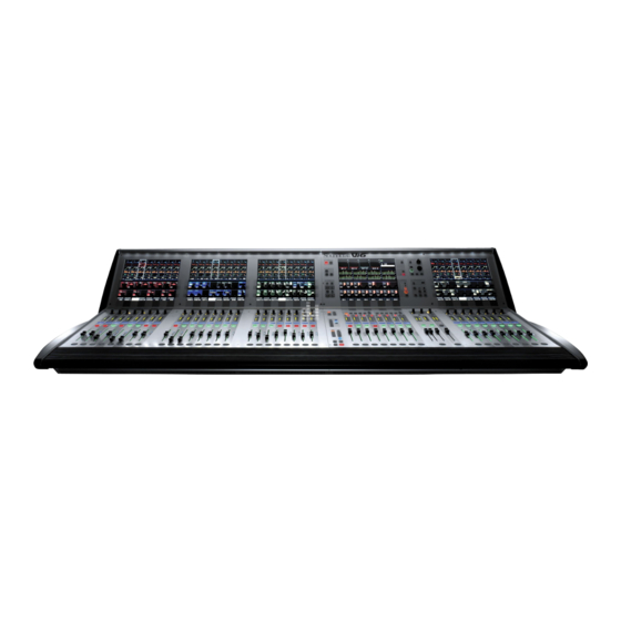
TECHNICAL INFORMATION MARCH 2007 The hardware for the Soundcraft Vi Series consoles comprise three main sections: The Main Console surface with all the mix controls and faders and Vistonics™ II screens. The Local Rack which is located near the console, and contains the DSP processing engine as well as some I/O. -
Page 3: Stage Box
System Hardware Diagram Stage Box 64 Analogue 35 Analogue Mic/Line Inputs Line Outputs (48 on Soundcraft Vi4) (27 on Soundcraft Vi4) Optional 4 pairs of Optional 4 pairs AES/EBU inputs card AES/EBU outputs card RS2446 RS2447 (replaces 8 Mic/Line (replaces 8 Line... - Page 4 Local Rack The Local Rack is located near the main There is also an optical MADI I/O card Console surface, and links to the surface which provides an additional 64 channels are via a simple Cat5 data link cable, plus of input and output for applications such three audio connections for headphones, as hard disk recording or broadcast feeds.
- Page 5 Stage Box MADI HD (option) (option) The Stage box contains the main Input If required, the Stagebox can be supplied GPIO connections for all microphones and with a fibre-optic redundant connection to There are 8 sets of GPIO (general line level sources, and also acts as the the Local Rack.
- Page 6 PATCH INPUTS INPUT CHANNELS / MATRIX / CASCADE MASTER SOLO MIC/LINE STAGE BOX PROCESSING INP 1 MASTER L DYNAMIC INP 2 & MASTER R PHASE EQUALIZER GATE/Dees Limiter DELAY FADER TRIM 4 band param Compressor MASTER C LINK (ST) Follow/ INS RET Bundle SC/ES...
-
Page 7: Block Diagram
PATCH OUTPUTS MASTER / MIX / MONITORING SOLO Block Diagram LINE OUT STAGE BOX MASTER LEFT (showing Soundcraft Vi6) DYNAMIC LEVEL LOW- MASTER L EQUALIZER Limiter FADER DELAY 4 band Compressor to MTX LINK SOLO TRIM INS SEND MASTER RIGHT... -
Page 8: Cable Specifications
Cat 5e: Suitable cable is available from Maximum 130m (422 feet) using AMP Maximum 80m (260 feet) using Soundcraft on a lightweight drum in Netconnect 57893 PiMF cable. Neutrik Etherflex Cat 5e cable the following lengths: (ZNK CT2672601), terminated with... - Page 9 When mounting the DSP core and stagebox and fans in a non- Soundcraft flightcase or rack, allow for cabling and connector space behind unit. Do not install without supplied fans. The DSP Core requires an additional 4U XLR breakout box to be mounted behind the rack (not shown).
- Page 10 Dimensions, Flightcased (Deluxe) Soundcraft Vi6 shown. For Soundcraft Vi4, deduct 310mm Soundcraft Vi6™ Deluxe Control Surface Flightcase - Dimensions 960mm 1840mm 565mm Soundcraft Vi6 1840mm Soundcraft Vi4 1530mm 1200mm This case is available with or without the integral stand (Soundcraft Vi6 735mm only).
- Page 11 Dimensions, Flightcased (Standard) Soundcraft Vi6 shown. For Soundcraft Vi4, deduct 310mm Soundcraft Vi6™ Deluxe Control Surface Flightcase - Dimensions Soundcraft Vi6™ Deluxe Control Surface Flightcase - Dimensions 960mm 960mm 1840mm 565mm 1840mm 565mm Soundcraft Vi6 1820mm Soundcraft Vi4 1510mm Dimensions when cased:...
-
Page 12: Technical Specifications
Technical Specifications Soundcraft reserves the right to improve or otherwise alter any information supplied in this document or any other documentation supplied hereafter. E&OE 03/06 Frequency Response Stagebox Mic input to Line output........................+0/-1dB, 20Hz-20kHz AES/EBU In to AES/EBU Out........................+0/-0.2dB, 20Hz-20kHz T.H.D.


Need help?
Do you have a question about the VI Series and is the answer not in the manual?
Questions and answers