Table of Contents
Advertisement
Advertisement
Table of Contents
Troubleshooting

Related Manuals for ATV 250


Summary of Contents for ATV 250
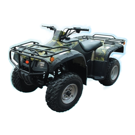
- Page 2 BRIEF INTRODUCTION TO FOUR-WHEELED CROSS-COUNTRY VEHICLE MODEL 250ATV Four-wheeled cross -country vehicle, model 250ATV is a full road condition vehicle which can be driven on every kinds of road conditions such as sand beach, grassland, forest,village, construction site country road , This maintenance manual of four-wheeled vehicle model 250ATV (Hereafter called cross -country vehicle for short) compiled by Chongqing Industries Co., Ltd is specially provided for saler and technical staff of our Group.
-
Page 3: Table Of Contents
(2) Lubrication diagram ......................27 Section 9 Lubrication point and type of lubricants ................29 (1) Lubrication point and type of lubricants(ATV body) ............29 (2) Lubrication point and type of lubricants(Engine) ............... 30 Chapter II Maintenance and adjustment of vehicle ................31 Section 1 Periodic maintenance/ lubrication .................. - Page 4 (IV) Front fender ........................37 Section 3 Maintenance and adjustment of vehicle body ..............39 (I) Wear inspection of front and rear brake ................39 (II) Adjustment of front brake ....................39 (III)Adjustment of free clearance of left lever and rear brake pedal ......... 40 (IV) Position adjustmen of steering lever .................
- Page 5 (VII) Installation ........................75 Section 2 Front wheel and front brake ....................76 (I) Disassembly ........................76 (II) Inspecting procedures ...................... 78 (III) Installation procedures ....................81 Section 3 Rear wheel/Rear brake/Rear wheel axle ..............84 (I) Removal steps ........................85 (II) Inspection steps .......................
- Page 6 (III) If the HB indicated lamp is out of work ................141 Chapter V Engine ..........................142 Section 1 Disassembly of engine ....................... 142 (I) Remove the engine from finished ATV ................142 (II) Disassembly of engine ...................... 145 section 2 Inspection and maintenance of engine ................159 Section 3 Assembly and adjustment of engine ..................
-
Page 7: Chapter I General Description
16.Left lever of rear brake 17.Fixing clamp of rear brake 18.Main switch lock 19.Throttle grip 20.Right lever of front brake 21. Left switch unit Caution: The ATV you purchased maybe slightly differ from the pictures in the manual due to improvement or other changement. -
Page 8: Section 2 Special Tools, Instruments & Meters
Section 2 Special tools, instruments and meters (I) Special tools Special tools is the necessary tools used for accurately adjustment and assembly, it is helpful to prevent the maintenance defects and components damage caused by using improper tools. 1.Wrench for valve adjustment mainly used for adjusting valve clearance. Specification: 3mm 90890-01311 2.Puller for piston pin, mainly used of removing pistion pin. -
Page 9: (Ii) Instruments & Tools
(II) Instruments and meters The following instruments and meters can be selected with reference to the same type of vehicle. speedometer of engine multimeter (90890-03113) Ignition timing meter spark tester of spark plug (90890-03141) barometer ignition checker measuring tool of gasoling dial indicator (90890-01312) -
Page 10: Section 3 Identification Code, Label Of Model And Engine No
3.1 When disassembling to maintain the of each other when operation with other people. engine, in order to ensure that the reassembled 1.4 When disassembling the ATV, put the engine have good sealing and connecting part is mated components, such as gear pairs, cylinder, fixed and reliable, all the oil seal, shim, o-ring, piston and other “mated”... - Page 11 4. Clip 4.1Before assembling, be sure to check all the clips carefully.Use a new one after remov- ing the clip of piston pin. When mounting clip ring ¢Ùmake the sharp face ¢Úon the opposite position of impacted face ¢Ûof clip.(see left fig) 5.Locking washer /shim and location pin 5.1When reassembling after disassembling.
- Page 12 7.Check of electirc parts 7.1 Check the rust, dirt and moisture etc. of connector, if there is moisture, please blow it dry and clear the rust and dirt. 7.2 The eclectolyte inside the battery is a kind of corrosive, when operation exercise shall be taken not to let the electrolyte splash on the body.
- Page 13 b. If joint is slack, bend the plug pin upward, then connect with connector plug(see fig7.5) 7.6 Before mounting new fuse, check if the load of fuse of components is right, especially Plug pin for the portion being burned broken regularly, then mount the fuse having proper current value.
-
Page 14: Section 5 Specification
Section 5 Specification (I) How to use conversion table of unit (1)How to use conversion table All the specified documents in this manual are taken SI and Metric as unit. With the follow- ing conversion table, metric unit could be conversed into imperial unit. METRIC MULTIPLY IMPERIAL... -
Page 15: Ii.basic Specification
II.Basic specification... -
Page 16: Iii.atv Body
III.ATV body Item Standard Limit Steering system Powder metallurgy sliding bearing Type of steering bearing Spock rim, tubeless tire Type Steel plate Material of rim Front AT 23¡Á7-10 Size of tire wheel AT 10 ¡Á5.5 Size of rim Radial runout of rim 2.0mm... -
Page 17: Iv.electric System
Item Standard Limit 10N/mm/0-117mm Elastic coefficient of spring K1 Front Free length of suspending spring 293mm suspen- sion Stoke of shock absorber 117mm system Pre-tension force of spring is Can’t adjustable adjsutable or not 49N/mm/0-85mm Elastic coefficient K2 Rear Free length of suspending spring 263mm suspen- sion... - Page 18 Item Standard Limit At 20¡æ(68 F),189-231¦¸ Blue black Resistance of induction coil/colour Magneto Resistance of source coil /colour At 20¡æ (68 F),470-530¦¸ Yellow/green-red Type of C.D.I Electric capacity contactless type 14.1-14.9V No-loading adjusting volatage Rectifier Voltage-resisting value 200V A.C magneto Type Charging Rated ouput voltage...
-
Page 19: Maintenance Specification Of Engine
V.Maintenance specificationof engine -13-... - Page 20 -14-...
- Page 21 -15-...
-
Page 22: Section 6 Wiring Diagram Of Atv
Section 6 Wiring diagram of ATV (I)Thechnical explanation and requirement, details of relative compenent. 1.Technical explanation T When assembling the wire of ser. No. A Main switch wire, indicator wire, mile- 14 and No.15.don’t need to put through the guide age meter wire (mounting digital mileage meter) clip of holdig seat of steering bar.(see fig.E-E) - Page 23 Vent-pipe of battery 2.Technical requirement SSA4-230000-0 Vent-pipe of front ¢ÙIn the drawing, the wiring condition and position for all kinds of wires on the ATV body Wire of headlight is marked. When assembling the finished ATV, SSA4-230000-0 Rear brake cable...
-
Page 24: (Ii) Wiring Diagram(1)
(II)Wiring diagram(1) Fig.1 Fig.2 -18-... -
Page 25: (Iii) Wiring Diagram(2)
(III)Wiring diagram(2) Fig.3 Fig.4 View F -19-... -
Page 26: (Iv) Wiring Diagram(3)
(IV)Wiring diagram(3) View C View A -20-... -
Page 27: Section 7 Requirements For Torque Of Fastener
(I)ATV body Torque value of fastener Tightening torque of Remark Name of Size of Locking component and fastener of ATV body Q’ty location of ATV body component thread Nm m.kg ft.lb Front wheel rim and front brake hub M10 ¡Á1.25 Front brake hub and steering vertical post units M12 ¡Á1.25... - Page 28 Tightening torque of Remark Name of Size of Locking component and fastener of ATV body Q’ty location of ATV body component thread Nm m.kg ft.lb Bolt M8 ¡Á16 Bolt Rear fender and rear luggage carrier M6 ¡Á20 Bolt Left&right foot rest and frame M10 ¡Á22...
-
Page 29: Engine
(II) Engine Torque value of fastener Tightening torque of Name of Size of Locking component and fastener of ATV body Q’ty Remark location of ATV body component thread Nm m.kg ft.lb Observing screw hole of cylinder head Cap shaped nut... - Page 30 Tightening torque of Name of Size of Locking component and fastener of ATV body Q’ty Remark location of ATV body component thread Nm m.kg ft.lb Bolt Exhaust pipe Screw Crankcase(closing case) Screw Left side cover Screw Left crankcase cover Screw...
-
Page 31: General Torque Specification
Tightening torque of Name of Size of Locking component and fastener of ATV body Q’ty Remark component thread location of ATV body Nm m.kg ft.lb Shift pedal Bolt Magneto stator Screw Neutral switch Reverse gear switch Hand-started driving disc Screw pin... -
Page 32: Section 8 Lubrication
Section 8 Lubrication Standard Item (I) Lubrication oil way :Pressure :Splashing oil Piston/cylinder Piston pin Connecting rod Valve Crank Camshaft Rocker Automatic centrifugal clutch Bearing Spindle Fine filter Branch valve Sprocket chamber Driving shaft Oil pump Middle gearbox Rough filter -26-... -
Page 33: Lubrication Diagram
(II) Lubrication diagram 1. Oil draining plug 8. Oil pump driving gear 2. O-ring 9. Camshaft 3. Compressing spring 10. Crankcase 4. Rough filter 11. Crank 5. Oil pump washer 12. Spindle 6. Oil pump assy 13. Driving shaft 7. Oil pump driven gear 14. - Page 34 1. Single-direction valve 8. Single-direction bearing(automatic centrifu- 2. Engine oil fine filter gal clutch) 3. Engine oil filter cover 9. Crank pin 4. O-ring 10. Crank pin 5. Clip 11. Spindel 6. camshaft 12. Driving shaft 7. Rocker -28-...
-
Page 35: Section 9 Lubrication Point And Type Of Lubricants
Section 9 Lubrication point and type of lubricants (I)Lubrication point and type of lubricants(ATV body) Lubrication point Type of lubricants Lip of oil seal (full) Light lithium-base grease O-ring (full) Light lithium-base grease Steering shaft(upper end,lower end) Light lithium-base grease... -
Page 36: Lubrication Point And Type Of Lubricants(Engine)
(II)Lubrication point and type of lubricants(Engine) Lubrication point(name of component) Type of lubricant Lip of oil seal Light lithium-base grease (Crank,shift gear shaft,spindle,shift gear operation shaft) All bearing Lubricating-oil (Crank spindle, driving shaft, output shaft, balancing shaft,shift gear camshaft, pneumatic canshaft) O-ring Light lithium-base grease (Contact position of o-ring) -
Page 37: Chapter Ii Maintenance And Adjustment Of Vehicle
Chapter II MAINTENANCE AND ADJUSTMENT OF VEHICLE Note: The correct maintenance and adjustment are necessary to ensure vehicles, normal driving.The repair personnel should be familiar with the contents of this article. Section 1 Periodic Maintenance/Lubrication Every time Every Item Requirement month month month... -
Page 38: Section 2 Disassembly And Assembly Of Cushion, Fender And Fuel Tank
Section 2 Diassembly and assembly of Cushion, Fender and Fuel fank (1) Cushion 1.Disassembly ¢Ù (1) Place the vehicle on the horizontal ground. (2) Disassemble the cushion ¢Ù; Pull the cushion lock lever ¢Úupward, then raise the tail part of cushion. By that, you can disassemble the cushion. -
Page 39: (Ii) Rear Fender
(II) Rear fender 1.Disassembly (1)Place the vehicle on the horizsontal ground. (2)Disassemble the rear luggage carrier ¢Ù ¢Ù (3)Disassemble the cushion (see the centents of cushion disassembly in this section) (4)Disconnect the negative wire ¢Ýand posi- tive wire ¢Ü of battery. ¢à... - Page 40 2.Installation Operate according to reverse procedure of “Disassembly”.Pay attention to following points: (1)Install: Rear fender Bolt ¢Ù (rear fender and frame).The torsion is 7N.m. Bolt ¢Ùand rubber hood of protecting plate (rear fender and frame).The torsion is 7N.m. ¢Ù (2)Install: a.Battery ¢Ù...
-
Page 41: (Iii)Fuel Tank
(III)Fuel tank 1.Disassembly (1)Place the vehicle on the horizontal ground. (2)Disassemble the cushion (see“Cushion disassembly”of this section) (3)Remove the air hose ¢Ùon the fuel tank cover. (4)Remove: ¢Ù a.Bolt¢Ú , flat washer 30, installing bushing of upper cover of fuel tank, washer and rubber hood 2 of fuel tank. - Page 42 2.Installation Operate according to reverse procedure of “Disassembly”,and pay attention to followig points: (1)Install the fuel tank (2)Connect a.Air inlet pipe and hose b.Supporting pad of air pipe and air rubber pipe Caution The convext part on the ring should be foreward when installing the Supporting pad of air pipe.
-
Page 43: (Iv)Front Fender
(IV)Front fender 1.Disassembly: (1)Place the vehicle on the horizontal ground. (2)Disassemble the front luggage carrier ¢Ù. (3)Disassemble the front guarding plate ¢Ú . ¢Ú (4)Cut off the connecting wire¢Ùof headlight. (from connecting point) (5)Disassemble the bumper ¢Ú. (6)Disassemble the front fender ¢Ù. -37-... - Page 44 2.Installation: Operate according to reverse procedures of “Disassembly”. (1)Install: a.Front fender ¢Ù b.Bolt. The fastening torque is 7N.m c.Bolt. rubber hood of protecting plate:The fastening torque is 7N.m (2)Install the bumper ¢Ù. The fastening torque of bolt (bumper and frame)is 16N.m. ¢Ù...
-
Page 45: Section 3 Maintenance And Adjustment Of Vehicle Body
Section 3 Maintenance and Adjustment of Vechicle Body (I)Wear inspection of front&rear brake 1.Check the front brake (1)Brake the vehicle with front brake (2)Check: .Wear indication ¢Ù .If the wear indication reach the wear limit mark ¢Ú ,replace the brake shoe assy. Refer to section“Front wheel and front brake”in chapter VII. -
Page 46: (Iii)Adjustment Of Free Clearance Of Left Lever And Rear Brake Pedal
2.Adjustment Adjusting procedure of free clearance of right lever: .Loosen the locking nut¢Ù,and rotate the cable adjsuting screw ¢Úclockwise to reduce the tension of front brake cable. .Check the cable joint ¢Üof balancer¢Û to ex- amine the balance. .If unbalanced. rotate the two adjusting nuts ¢Ú... - Page 47 2.Adjust .Free clearance of left lever .Free clearance of rear brake pedal Adjusting procedure: Caution Before adjusting, tread the rear brake pedal 2-3times. .Loosen the locking nut completely, and screw in the cable adjusting screw completely. .Loosen the adjusting nut ¢Ûof rear brake cable and adjusting nut¢Ü...
-
Page 48: (Iv) Position Adjustmen Of Steering Lever
(IV)Position adjustment of steering lever .Position adjusting procedure of steering lever. .Place the vehicle on the flat guound. .Change the shift to the 1st gear, and pull the steering lever ¢Ùto reverse gear position. .Loosen the locking nut ¢Ú .Screw in or out the adjusting nut ¢Ûof steer- ing lever until the middle line of the tension rod plate aims at the alignment mark... -
Page 49: (Vi)Replacement Of Engine Oil Of Rear Driving Gear Case
(VI)Replacement of engine oil of rear driving gear case. 1.Place the vehicle on the flat ground. 2.Place an oil catcher under the rear driving gear case. 3.Remove: .Below cover of gear case. .oil Filling screw plug .oil draining screw plug ¢Ù Drain out the engine oil of the rear driving gear case. -
Page 50: (Vii) Inspection Of Steering System
(VII) Rubber sleeve inspection of rear wheel fork Check .Rubber sleeve ¢Ù If damaged or worn, replace it. Refer to the 6th section “Rear shock absorber and rear wheel fork” of chapter3. (VIII)Inspection of steering system 1.Place the vehicle on the flat ground 2.Check: .Clamp seat of steering vertical column and sliding bearing on the lower end of steering... -
Page 51: (Ix)Adjustment Of Toe-In Of Front Wheel
(IX)Adjustment of toe-in of front wheel, 1.Rest the motorcycle on the flat ground 2.Measurement: .Toe-in .Adjust if out of specification .Adjustment steps of toe-in. .Mark the centers of tire thread of two front wheel. .Lift the front end of motorcycle to keep the front wheel from force. -
Page 52: (X) Inspection Of Front/Rear Shock Absorber
(X)Inspecion of front/rear shock absorber 1.Rest the motorcycle on the flat ground 2.Inspection: .Ball joint assy ¢Ù(Upper part of front shock absorber ). If broken/Damaged. replace the front shock absober. .Rear shock rod ¢Ú (Rear shock absorber) If scraped/damaged. replace the rear shock absorber .Oil leakage ¢Û... -
Page 53: (Xii) Inspection Of Tire
.Tire characterics 1)Quality characterics of tire will affect the driving reliability of ATV. The following types of tires reliability by our company be used safely by this motorcycle. If adpot other tires it will cause the disadvantageous effect.So they are out of recommendation. -
Page 54: (Xiii)Inspection Of Rim
1.Measurement .Tire pressure(nomal atmospheric temperature): If out of specification, adjust. Caution .The manometer of tire belongs to spare parts of the motorcycle(Never use the high pressure). .If the foreign matters such as dust, etc are absorbed in the tire pressure manoeter, the readig of the meter will be not correct, at the moment, the second measurement should be conducted and the second measurment reading should be... -
Page 55: Section 4 Maintenance And Adjustment Of Electrical Appliance
Section 4 Maintenance and Adjustment of Electrical Appliance (I)Inspection of battery Warning: The electrolyte is dangerous article, whitch in- cludes sulphuric acid, so it is poisonous and corrosive. .Please operate by the following steps: a.Avoid the body touching the electrolyte so as to protect the eye from burn or damage. -
Page 56: (Ii)Inspection Of Fuse
5.Inspection of battery If damaged, replace it 6.Installment of battery ¢Û 7.Connect .Battery electrode(positiove electrode ¢Ù negative electrode ¢Ú ) First connect the positive electrode ¢Ù ¢Ú 8.Installment: ¢Û ¢Ù ¢Ü a.Battery clamp plate ¢Ü b.Cushion (II)Inspection of fuse Caution Closet the main switch when checking or re- placing the fuse, otherwise, it will cause the short circuit. -
Page 57: (Iii)Replacement Of Headlight Lamp
2.Replacement of fused fuse Replacement steps: .Cut off ignition and circuit. .Install the qualified fuse .Start the power for electrical appliance inspection. .If the fuse fused, inspect the system again Refer to “Elefctrical Appliance”of Chapter Four 3.Installment of fuse cover (III)Replacement of headlight lamp 1.Cut off .Connecting wire terminal of headlight ¢Ù... - Page 58 6.Installment .Lamp ¢Ù (new) Caution Be sure that the projective part on the lamp ¢Úis engaged with the convex groove ¢Ûon the light seat. Caution Never touch the glass part to avoid the camp to touch the fuel. Otherwise, the lamp will be light permeability, service life and Tlluminating value.If there is some oil, clean off with cloth mixed with alcohol.
-
Page 59: Section 5 Maintenance And Adjustment Of Engine
Section Five Maintainace and Adjustment of Engine (I)Adjustment of clutch Adjustment steps: a.Loosen the locking nut¢Ù b.Turn the adjusting screw rod ¢Úcounter- clockwise slowly up to be unable to turn,then turn1/8 clockwise, and fasten the adjusting screw rod¢Ú to this position and tighten up the locking nut¢Ùwith the torque of N.m. -
Page 61: (Iii)Inspection Of Spark Plug
(III)Inspection of spark plug 1.Rest the vehicle on the flat ground and lean the spark plug with compressed air to avoid the dust entering the engine. 2.Remove the spark plug ¢Ù The standard spark plug type: DTRTC, If not correct, replace it. 3.Inspection of spark plug ¢Ù... -
Page 62: (Iv)Adjustment Of Idle Speed
(IV)Adjustment of idle speed 1.Rest the vehicle on the flat ground 2.Start the engine and prewarm it at the speed of 1000-2000r/min, after several minutes, in- crease the engine speed to 4000-5000r/min. 3.Set the specified idle speed through adjust- ing the throttle adjusting screw ¢Ù , Screw in to incresase the engine speed and screw out to decrease the speed. -
Page 63: (Vi)Adjustment Of Speed Limitator
(VI)Adjustment of speed limitator: The speed limitator can limit the throttle in full opening condition when the throttle grip is pulled to the Max position, screwing the ad- juster inward can stop increasig the speed. 1.Adjust speed limiting length@ Adjustment steps: a.Loosen the locking nut ¢Ù... -
Page 64: (Vii)Adjustment Of Valve Clearance
(VII)Adjustment of valve clearance. Caution The valve clearance should be adjusting only after the engine is cold, the valve clearance should be adjusted when the piston is at the end point position of compress stroke. 1.Removal: 1)Rest the vehicle on the flat ground 2)Remvoe a.Cushion (Refer to section tow “Cushion Remvoal”of this chaper) - Page 65 b.Make the mark“T”on the rotor is align with the mark on the crankcase. When it is done that is the pistion ties in top dead center(TDC) c.Inspection of top dead center in pressure stoke: (i)When the mark¢Ùon the rotor is align with the mark ¢Úon the crankcase,the two arms must have clearance.
-
Page 66: (Viii)Adjustment Of Timing Chain Tension
3.Installation: Carry out it according to opposite steps of “Removal”. (1)Mount: a.Valve cap ¢Ù (Side of outlet door) b.Valve cap ¢Ú(Side of inlet door) Caution (i)Project of valve cap ¢Ù ¢Úsould be up ¢Û when mounting. (ii)Check if O-ring ¢Üis damaged. if any, re- place it immediately. -
Page 67: (Ix)Inspection Of Ignition Timing
(IX)Inspection of ignition timing Notice: Before checking the correct timed ignition adjust the engine idle speed and free clear- ance of throttle grip to correct position. 1.Put the vehicle on the flat groud. 2.Start the engine for pre-heating ,and then stop the engine. -
Page 68: (X)Measuring Of Compressive Force
(X)Measuring of compressive force Caution Inadequate compressive force will reduce the engine performance. Before measuring compressive force. Valve clearance should be adjusted first (refer to “Adjustment of valve clearance section). 1.Put the vehicle on the flat ground. 2.Take off spark plug. 3.The following is steps of measuring com- pressive force: a.Install pressure gauge... -
Page 69: (Xi) Inspection Oil Quantity Of Engine
d.If the pressure is lower than the min,value: (i)Drop some oil to action cylinder. (ii)Measure the pressure again Compression force(The machine oil has been filled in the cylinder) Compressure read Reason Piston or piston ring is Read is highter than one before filling worn or damaged Piston ring, throttle... -
Page 70: (Xii)Replacement Of Engine Oil And Inspection Of Oil Flow
b.Turn out the dipstick ¢Ùentirely, and clean it, then insert it¢Ùback into oil hole. c.Take out the dipstick ¢Ùto check if the oil level is between the Max. value and the Min. value ¢Û . d.If the oil quantity is too small, fill some en- gine oil to make the oil quantity get to proper quantity. - Page 71 6.Inspection One of parts of O-ring¢Ù , compressure spring ,rough filter ¢Û ,fine filter ¢Üis damaged, repalce it. 7.Cleaning Clean the compressure spring¢Ú, filter¢Û,filter ¢Ü, filter plug of crankcase¢Ý and filter net cap with cleaner. 8.Coat the engine oil on the O-ring slightly. 9.Install the fire filter¢Ù...
- Page 72 11.Mount dipstick 12.Pre-heat engine for 5 minutes or more, and then stop. 13.Check the oil flow Inspection steps: a.Loosen the bolt¢Ùof cylinder head lightly. b.Start the engine for racing until the machine oil squeeze out from oil tunnel. If there is no machine oil out for one minute, stop the en- gine at once for avoiding the engine is damaged.
-
Page 73: Chapter Iii Repair And Maintenance Of Vehicle Body
Chapter III Repair and Maintenance of Vehicle body Section 1Rear Driving Gear Case and Driving Shaft (I)Trouble .Trouble judging guidance Performance Possible reason 1.When the vehicle accelerates, decelerates or is in idle A.Damaged bearing start, there appears stop or irregular run-out with abnormal B.Improper clearance noise (pay attention not to confuse with trouble of engine) C.Damaged gear... -
Page 74: (Iii)Trouble-Shooting Table
to check the rust of bearing which will cause jam. Caution A little metal corpuscle in oil is normal. 3. Check the oil leakage Check according to following procedures. a.Clean the whole vehicle totally, then wipe and dry it. b.Paint inspecting solvent of oil leakage or dry powder on the transmission shaft c.Only enough examining distance (Suggestion ¡Ý... -
Page 75: (Iv)Disassembly
(IV)Disassembly Warning Support the vehicle firmly and ensure no turn- over 1.Drain the oil: The oil of rear driving gear case Refer to 3rd section“Replacement of engine oil of rear driving gear case”of chapter2. 2.Disassemble 1)Cushion 2)Rear luggage carrier 3)Rear fender Refer to 2nd section“rear fender”of chapter 3.Disassemble 1)Rear wheel(left) - Page 76 1.disassembly ¢Ù a.Remove bolt¢Ù M6 bolt ¢ÚM8 ¢Ú Caution Remove the bolts alternately. Loosen each bolt by 1/4 circle, and remove them after all of them are loosened. b. Disassemble: ¢Ù 1)Rear driving gear case body ¢Ù 2)Annular gear pad ¢Ú 3)Shift gear ¢Û...
- Page 77 d.Disassemble Tap the main driving gear lightly with soft hammer,and remove the main driving gear¢Ù (with thrust pad ¢Úand bearing ¢Û) Caution If it is necessary to replace ace the gear, should remove the main driving gear firstly. Do not use the original bearing thrust pad.
-
Page 78: (V)Inspection
(V)Inspection 1.Check the gear teeth of bevel gear pair ¢Ù Cave/scratch /wear ¡úreplace the main driv- ing gear and shift gear in set 2.Check oil seal ¢Ú 3.Check O-ring ¢Û If damaged, replace it. 4.Check the bearing ¢Ü If damaged, replace it. Caution The bearing can be used repeatedly. -
Page 79: (Vi)Pad Choice Of Main Driving Gear And Shift Gear
(VI)Pad choice of main driving gear and shift gear 1.Choice of main driving gear pad: Work out the main driving gear pad thickness“A”= =84 add or subtract the number engraved on the main driving =83.5 add or subtract the number engraved on the driving gear case body. - Page 80 2.Choice of shift gear pad Shift gear pad ¢Ù Chosing procedures: Work out the pad thickness “B”front follow- ing formula “B”= =45.5adds or subtracts the number en- graved on the driving gear case body. =1 adds or subtracts the number engraved on the driving gear case cover.
-
Page 81: (Vii)Installation
(VII)Installation: T h e p r o c e d u r e i s t h e r e v e r s a l o f “disassembly”.But pay attention to following points: 1.Install the needle bearing(small)on main driv- ing gear: Procedures:a.Warm the case body to 150¡æ... -
Page 82: Section 2 Front Wheel And Front Brake
Section 2 Front wheel and Front Brake Technical Parameter Item Parameter Ser No. Tire specification AT22¡Á7-10 Rim dimension 5.5¡Á10 Standard value 20KPa(Standard value) Tire air pressure(normal Min value 17KPa(Min vlaue) temperature) Max value 23KPa(Max value) Radia run-out Run-out End face run-act Tire wear limit value Wear limit value of friction wafer Wear limit value of front brake hub... - Page 83 3)Disassmeble split pin¢Ù, slotted nut¢Ú ,plain washer ¢Û,front brake ¢Ü and gasket ¢Ý . 4)Disassmeble adjusting nut¢Ù, pin¢Ú, spring ¢Û, circlip ¢Ü spring ¢Ýand circlip ¢Þ. 5)Remove the front brake cable and front brake air pipe. ¢Ú 6)Disassemble brake shoe assy ¢Ùand front cover assy ¢Ú...
-
Page 84: Ii.inspecting Procedures
II.Inspecting procedures 1.Check Front wheel:refer to “Tire inspection”and “Hub inspection”of chapter2. 2.Measure Radial run-out of front wheel:If exceeding the specified limit, replace the front wheel or check the bearing clearance(¢Ùin figure) Attached:Rim run-out limit: Radial run-out 2.0mm(¢Úin figure) End face run-out 2.0mm(¢Ûin figure) 3.Check: Tire surface:If worn or damaged, replace it. - Page 85 4.Check Friction wafer:polish the surface needing polishment with rough sand paper. 5.Measure Thickness of friction wafer of brake: if it does not conform to specified thickness, replace it . Attached: Thicknes of friction wafer of brake:4.0mm Wear limit :2.0mm Caution ¢Ù...
-
Page 87: (Iii) Installation Procedures
(III)Installation procedure: The installation procedure is the riversal of “Disassembly ”.But pay attention to following points: 1.Lubrication:as shown in figure: ¢ÙDust-proof seal ¢ÚBearing ¢ÛCam shaft ¢ÜRotating pin seat ¢Ý“O”sealing ring Attached:use lithum base grease Warning When installing the cam shaft and rotating pin seat, should apply a little grease firstly. - Page 88 4.Install Brake shoe assy Do not apply lubricating grease on brake fric- tion wafer. 5.Connect a.front brake air pipe. b. connect the front brake cable with brake cover. 6.Install (as shown in figure) ¢ÙCirclip ¢ÚSpring ¢ÛCirclip ¢ÜSpring ¢ÝPin ¢ÞAdjusting nut 7.Install(as shown in figure) ¢ÙFront brake hub ¢ÚGakset, O-ring 17 ¡Á1.8G...
- Page 89 9.Installment: When installing the front wheel¢Ù , the fasten- ing torque of connecting nut¢Ú of front and rear wheels is 55N.m. The rotation direction of front wheel (A) is the arrow direction marked on the tire. 10.Adjustment Free clearance of front brake cable R e f e r t o t h e “...
-
Page 90: Section 3 Rear Wheel/Rear Brake/Rear Wheel Axle
Section 3 Rear wheel/rear brake/rear wheel axle Technical Parameter Item Parameter Ser No. Tire specification AT22 ¡Á10-10 Rim dimension 8.5 ¡Á10 Standard value 25KPa(Standard value) Tire air pressure(normal Min value 22KPa(Min vlaue) temperature) Max value 28KPa(Max value) Radia run-out Run-out End face run-act Wear limit of tire Wear limit of friction disk... -
Page 91: (I)Removal Steps
(I)Removal steps 1.Rest the motorcycle on a flat ground.Press the rear brake clip ¢Ù . 2.Loosen the connecting nuts of front and rear wheels. 3.Stop up the front wheel with wood, then put a proper supporting article under the frame so as to lift the rear wheel and make the rear wheel leave the earth. - Page 92 8.Removal:(the ser.No as shown on the drawing) ¢ÙAdjusting nut, pin and spring of rear brake arm and rear brake tension rod assy. 9.Removal: ¢ÚRear brake calbe ¢ÛRear brake Tension rod assy ¢ÜAir pipe of rear brake 10.Removal: ¢ÙRear brake bearing block ¢ÚRear brake hub 11.Removal: ¢ÙTension spring...
-
Page 93: (Ii)Inspection Steps
(II)Inspection steps: 1.Inspection When inspecting the real wheel, refer to “tire Inspection”,“Rim inspection”Section of chap- ter Two. 2.Measurement: a.radial runout of rim b.tire surface Refer to“Front wheel and Front Brake Inspection”Section of this chapter 3.Inspection ¢ÙRear wheel connection plate ¢Ù ,If cracks or damage is found, replace it. - Page 94 8.Inspection(The Ser.No as shown on the drawing) ¢ÙInner surface of rear brake hub If there is some engine oil or scraped markings, remove it and treat it ,the mothod of treat is as the follows. Removal of engine oil:Clean with colth dipped in volatile diluent or volatile solvent.
- Page 95 13.Measurement The radial runout of the pisition @on the rear wheel axle, if out of specification, repalce it. Attached:The radial runout limit of rear wheel axle:1.5mm Warning If the axle is bent, do not straighten it forcefully. 14.Inspection: ¢ÙBearing on the rear wheel axle Rotate the rear wheel axle, if the axle shakes left and right in the bearing or runout axially, It indicated that the bearing is heavily worn need-...
-
Page 96: (Iii)Installment Steps
(III)Installment steps: The reversal steps of “removal steps”,that is installment steps.Pay attention to the follow- ing points when installing: 1.Lubrication part ¢ÙOil seal lip of rear wheel axle. ¢ÚBearing of rear wheel axle. The corresponding spline tooth of rear wheel axle. - Page 97 5.Installment ¢ÙCam shaft of rear brake ¢Ù ¢ÚIndicating plate of brake ¢Ú ¢ÛRear brake arm assy ¢Û Caution When installing the brake indicatinig plate¢Ú to rear brake can shaft ¢Ù,be sure to align the projective part@of brake indicating plate ¢Ú with the concave part of rear brake cam shaft ¢Ù...
- Page 98 8.Installment Barke shoe assy 9.Lubrication Dust-proof seal Lubrication oil for dust-proof seal:lithium base grease. Warning The lubrication oil is not allowed to be used for brake shoe assy, the lithium base grease is used for rear brake hub spline groove. Warning The lubrication oil is not allowed to be used for spline on the right end of rear wheel axle,...
- Page 99 15.Installment split pin4 ¡Á30 ¢Ù Caution After fastening the forque, the nut on the rear wheel axle is not allowed to be loose. If the nut concave groove is not align with the splint hole on the screw rod, make it by tightening up the nut.
-
Page 100: Section 3 Steering Operation System
Section 3 Steering Operation System (I)Removal steps of steering bar 1.Removal Front luggage carrier Bumper Front fender Refer to chapterTwo.Section Two 2.Removal Main switch lock wire “Neutral”indicating light wire “Reverse”indicating light wire “High beam”indicating light wire Clutch switch wire 3.Removal ¢Ù... -
Page 101: (Ii)Removal Steps Of Steering Vertical Column Welding
(II)Removal steps of steering vertical column welding 1.Plain move ¢ÙThe locking part of locking pad as shown 2.Removal ¢ÚBolt M8 ¡Á60 ¢ÛLocking washer ¢ÜClip assy 3.Remocal Install the steering vertical column with split 2.25 ¡Á24 Nut M10 Washer 10 4.Removal Split pin Nut M12 ¡Á1.25 Tension rod ¢Ù... -
Page 102: (Iii)Inspection Content
(III)Inspection content 1.Check if the steering bar is cracks bent, is bent or damaged. If it is, replace it. 2.Inspect if the steering vertical column weld- ing assy is bent or damaged. if it is, replace it Warning In order to avoid decreasing the performance of steering vertical column, if it is bent do not straighten it frocefully. -
Page 103: (Iv)Installment Steps
6.Adjustment Assembly length of tension rod Adjustment steps of tension rod assembly length Loosen the connecting nut (A).(B) Adjusting the assembly length of tension rod by rotating the tension rod. Attached:Tension rod assembly length @: 297mm (A)Right-hand thread (B)Left-hand thread Connect (C)position to the steering vertical col- umn welding assy. - Page 104 2.Lubricate the steering vertical column holder ¢Ùand seal ring ¢Úduring installing the steer- ing vertical column welding. 3.Installment Install the seal ring ¢Ùto the steering vertical column welding, then install bushing¢Ú, finally install the steering vertical column holder¢Û. Caution: Never damage the seal ring when installing. 4.Installment When installing the steering vertical column holder and steering vertical cotumn welding...
- Page 105 7.Mounting split pin¢Ù Caution Don’t loosen the nut after the torque is fixed. If the nut recess is not correspondance with split pin hole on the double -screw bolt, tighten the nut to align them. Warning Always use new split pin 8.Tighting After mounting the washer,nut, split pin under the steering vertical column.
-
Page 106: (V)Installation Steps Of Steering Bar
(V)Installation steps of steering bar 1.Install the lower holding seat¢Ù , steering tube ¢Ú and upper holding seat ¢Û . Warning When tightening the bolt of holding seat, make ensure the even of clearance Attached:bolt torque:20Nm 2.Install the throttle grip unit Caution The projection ¢Ùof throttle grip must corre- spond to the sunken part ¢Úon the right lever... -
Page 107: Section 4 Front Shock Absorber And Front Wheel Fork
Section 4 Front shock absorber and Front wheel fork (I)Disassembly: 1.Take off front luggage carrier, bumper, front feder. Refer to the second section of chapter2 Disassemble the front wheel front brake hub. brake shoe unit and front brake cap unit Refer to “Dischargement of front wheel and front brake”of this chapter 2.Take off split pin¢Ù, nut¢Ú... - Page 108 7.Check the free clearance of left/right front wheel fork Inspection step: a:Check the parts ¢Ù of let/right front wheel fork on the frame, if it is bend, crack or worn repair or replace the frame. b:Check the torque value of locking nut on the left/right front wheel fork Attached:Nut torque value:45Nm c:Move the left/right front wheel fork from one...
-
Page 109: (Ii) Inspection Steps
(II)Inspection step 1.Check the front shock absorber. If it is leak- age ,replace it .Check the universal joint.If it is crack or damaged,replace the front shock absorber. Check spring, if it is fatigue or damage, re- place the front shock absorbe.(When checking, move the spring up and down) 2.Check the front seat assy of front brake, if it is crack sunk or damaged, replace it. -
Page 110: (Iii)Installment Steps
(III)Installment steps The opposit steps of “Disassembly”is the mounting steps. The following must be paid attention when mounting: 1.Lubricate the inner surface of bushing sub- assembly ¢Ù .(Lubrication oil is lithium base grease). 2.Fix nut Nut torque:45Nm Caution Must ensure the correctionof bolt mounting direction of left /right front wheel fork, bolt head position is the position showing on the drawing¢Ùfront, behind¢Ú... - Page 111 5.Mount the split pin ¢Û Caution Don’t loosen the nut after marking the stan- dard torque.If the recess on the nut is not cor- respondence with split pin hole on the bolt, correct it by tightening the nut. Warning Must use new split pin. 6.Mount: Front shock absrober ,front shock absorber nut ¢Ý...
- Page 112 Caution Don’t loosen the nut after markingthe stan- dard torque.If the recess on the nut is not cor- respondence with the split pin on the bolt, cor- rect it by fixing the nut. Warning Must use new split pin ¢Û 10.Mount front brake cap assy brake shoe assy front brake hub and front wheel.
-
Page 113: Section 5 Rear Shock Absorber And Rear Wheel Fork
Section 5 Rear shock absorber and Rear wheel fork (I)Disassembling steps 1.Take off left rear wheel, rear wheel joint plate right rear wheel rear brake hub, rear brake and rear wheel axle. Refer to “Disassembly of rear wheel/rear brake and rear wheel axle”section in this chapter. - Page 114 5.Take off nut ¢Ùon the rear shock absorber, bolt ¢Ú ,rear shock absorber ¢Û. 6.Take off rear brake tension spring ¢Ù 7.Take off dusty cap on rear arm axle (¢Ù.¢Ú point) 8.Check the free clearance of rear wheel fork checking steps. a:Check the torque value of rear arm joint bolt ¢Ùand the torque value of rear arm bolt ¢Ú...
-
Page 115: (Ii)Checking Steps
9.Take off rear bush ¢Ù 10.Take off driving axle clamp assy(front)¢Ù, rear arm nut (right side)and rear arm joint bolt. 11.Take off rear wheel fork assy ¢Ù . (II)Checking steps 1.Check a:If rear shock absorber is leakage, if any , replace it. - Page 116 2.Check if the rear wheel fork assy is crack bend and damaged, if any, replace it. Check if the rear wheel bush is crack, bend and damaged. If there is one of these prob- lems replace it. 3.Check the gear case lower cap, if there is one of crack bend damagement problems, re- place this part.
-
Page 117: (Iii) Mounting
Take off bearing ¢Û with usually bearing tool The reverse step of “bearig and oil sealing re- placing step”is the mounting step of new bear- ing and new oil sealing. Caution Use a pressure tooling ¢Ü which is match with outer diameter of bearing race ¢ß... - Page 118 3.Fix the rear arm joint bolt ¢Ù(left),rear arm joint bolt¢Ú(right)and bush¢Û . Fixing steps: a:Fix the left t rear arm joint bolt ¢Ùby stan- dard torque. b:Fix the right rear arm joint bult¢Úuntil it con- tact with its bush ¢Û . Attached:Bolt torque :6Nm c:Fix right rear arm nut ¢Ü...
- Page 119 8.Mount the rear driving gear case sub-assem- bly ¢Ù Refer to “Installation of rear driving gear case sub-assembly and driving shaft ”section of this chapter. 9.Mount the rear wheel axle, rear brake, rear ¢Ù brake hub, right rear wheel, rear wheel joint plate and left rear wheel.
-
Page 120: Chapter Iv Electric Appliance
Chapter IV Electric Appliance Section 1 Inspect switch (I)Inspect switch Inspect if the circuit between wire end is on with pocket multimeter. If there is any failure ,replace the switch. Pocket multimter Remark .Adjust the multimeter to “O”before inspect- .Adjust the multimeter to “ ¦ ¸ ¡ Á 1”when in- specting the circuit. -
Page 121: Section 2 Check Lamp(Headlight)
Section 2 Check Lamp (headlight) Check the lamp condition 1.Remove the lamp Caution Pay attention to support the lamp seat. Don’t pull the lead wire, otherwise it wil be broke. Warning When the headlight light up, please remove the inflammable and your hand from the lamp.Because it will be very hot,you can touch it only until it is cool. - Page 122 -116-...
-
Page 123: Section 3 Troubleshooting The Ignition System Failure
Section 3 Troubleshooting the ignition system failure If the ignition system does not work(no spark or spark stops) Step Check 1.Spark plug 6.Main switch 2.Ignition park clearance 7.Resistance value of triggering coil 3.Resistance value of spark plug cap 8.Resistance value of charge coil 4.Resistance value of ignition coil 9.Circuit connection (whole ignition system) 5.Engine stop switch... - Page 124 2.Ignition spark clearance .Remove the spark plug cap from spark plug .Connect as shown in figure ¢ÙSpark testing instrument ¢ÚSpark plug cap ¢ÛSpark plug .Rotate the main switch to “ON” .Check the ignition spark clearance. .Press down the starting switch to start the engine. And increase the spark clearance until the engine can not be started.
- Page 125 .Inspect if the resistance of primary coil con- forms to specification Primary coil resistance 20¡æ(68¡ã F)0.43~0.5 ¦¸ .Connect the multitester£¨¦¸¡Á1K£©to ignition coil .Inspect if the secondary coil resitance conforms to specification Not conforming to specification Secondary coil resistance 20¡æ(68¡ãF)4.6-7.6K ¦¸ Replace ignition coil All conform to specification Abnormal...
- Page 126 8.Resistance value of charge coil .Remove the corresponding connector of charge coil from cable. .Connect the mulitester( ¡Á100 ) to wire end ¦¸ of charge coil Multitester pen (+) ¡ú yellow/green wire end ¢Ù Multitester pen (-) ¡ú yellow/green wire end ¢Ú Inspect if the resistance value conform to speci- Not conforming to specification fication...
- Page 127 -121-...
-
Page 128: Section 4 Running Of Starting Circuit
Section 4 Running of starting circuit The starting circuit of this vehicle include start- ing motor, cut-off relay, rear brake switch and neutral switch. If the main switch is in position, the startig motor could be operated only at the following conditions: .Driving device is at neutral position(neutral switch is closed) -
Page 129: Section 5 Troublshooting Electric Starting System
Section 5 Troubleshooting electric starting system If starting motor doesn’t work 6.Main switch 7.Neutral switch 8.Rear brake switch 9.Staring switch 10.Circuit connection(Whole starting system) Pocket-multimeter Remark .Remove the following parts before troubleshooting 1)Cushion 2)Front frame 3)Front fender .Use the following special tool to troubleshoot No electrification 1.Safety Refer to “check of switch”... - Page 130 No rotation Repair or replace starting motor 4.Power off relay .Remove the relay from cable .Connect portable multitester (¦¸¡Á1)and battery (12V) to wire end of power off relay Battery end(+)¡úred/white wire end ¢Ù Battery end(-)¡úgreen/yellow wire end ¢Ú Multitester pen(+)¡úred/white wire end ¢Ù Multitester pen(-)¡úblue/white wire end ¢Û...
- Page 131 Incorrect 6.Main switch Refer to “Check switch” Replace main switch Correct Incorrect 7.Neutral switch Refer to “Check switch” Correct Incorrect 8.Rear brake switch Refer to “Check switch” Replace rear brake switch Correct Incorrect 9.Starting switch Refer to “Check switch” Replace handlebar switch (left) Correct Incorrect 10.Circuit connection...
-
Page 132: Section 6 Check Starting Motor
Section 6 Check starting Motor 1.Check .Reverser Not clean ¡úClean with #600 sand paper 2.Ensure .Reverser diameter @ Not conforming to specification ¡úchange the startig motor Outer diameter 28mm(1.10in) (Wear range) 27mm(1.06 in) 3.Measure .Mica cut sheet Not conform to specification ¡úScrape the mica with square scraper Mica cut sheet:0.7mm(0.028 in) Remark... - Page 133 5.Measure .Length @of brush (every one) Out of specification ¡úreplace it Length of brush:10mm(0.39 inches) Range of wear:<6mm(0.14 inches)> 6.Measure .Brushing spring force Fatigue/out of specification ¡ú replace whole device Brushing spring force:326~970g(3.2~3. 7.Check .Oil sealing .Bushing .O-ring Wear/damage ¡úrepalce it Installation of starting motor: 1.Mount .Magnetic steel...
- Page 134 -128-...
-
Page 135: Section 7 No Charging In The Battery
Section 7 No charging in the Battery Steps Check: 4.Startor coil 1.Safety 5.Coupling of circuit 2.Battery (Whole charging system) 3.Charging voltage Coil techometer Remark Engine techometer .Remove some parts before maintenance 1)Cushion Pocket multimeter .Repair with following special toolings NO.electrification 1.Safety Refer to “Inspection of switch”... - Page 136 .Start the engine and accelerate to 2000r/m or so. Meet specification Charging voltage:14-15V at 2000r/m Remark: Use battery with full capacity No failure on charging circuit Oil of specification 4.Resistance value for startor coil .Take out the lighting coil of AC magneto from in- serter .Connect pocket multiconeter to stator coil(¦...
- Page 137 -131-...
-
Page 138: Section 8 Troubleshooting
Section 8 Troubleshooting If the headlight or taillight is not work Steps Check: 1.Safety 4.Lamp switch 2.Battery 5.Coupling of wires(for entire lighting system) 3.Main switch Pocket multimeter:P/N YU-03112 Remark: 90890-03112 .Remove out the following parts before main- tenance of troubleshooting 1)Cushion 2)Front luggage carrier 3)Front covering parts... - Page 139 Incorrect 4.Switch for lamps Refer to “Inspection of switch” Correct If the lamp switch is failure replace the switch of handle(left) 5.Coupling of wires .Check the wire compling or whole lighting sys- Poor coupling Refer to “Diagram” Correct Connect whole lighting system correctly. Check the returning condition of each lighting system.
-
Page 140: Section 9 Inspection Of Lighting System
Section 9 Inspection of Lighting system (I)If the headlight is out of work 1.Bulb and bulb socket No electrification .Check the bulb and bulb socket condition Replace bulb and bulb socket 2.Voltage: Connect multimeter to the coupler of head- light socket(DC,20V) Multimeter(+)¡úgreen terminal ¢Ù... -
Page 141: (Ii)If The Taillight Is Out Of Work
(II)If the taillight is out of work No electricfication 1.Bulb and bulb socket .Check if the bulb and bulb socket is correct Meet specification Replace bulb and bulb socket 2.Voltage .Connect the pocket tester (DC 20V)to the terminal of taillamp. Multimeter (+)¡úblue terminal ¢Ù... - Page 142 -136-...
-
Page 143: Section 10 Troubleshooting
Section 10 Troubleshooting (I)If indicated lamp is out of work Steps Check: 1.Safety 4.Coupling of wires 2.Battery Pocket multimeter (Whole signal system) 3.Front switch Remark: . R e m o v e t h e f o l l o w i n g p a r t s b e f o r e troubleshooting. - Page 144 Incorrect 3.Main switch Refer to “Inspection of switch” Correct Replace main switch 4.Coupling of wires .Check the coupling of whole signal system wires Poor connection Refer to “Diagram of wires” Correct Connect it correctly Check each signal system condition Refer to“Inspection of signal system” -138-...
-
Page 145: Section 11 Inspection Of Signal System
Section 11 Inspection of Signal system (I)If the neutral indicated lamp is out of work No electrification 1.Bulb and bulb socket .Check if bulb and bulb socket circuit is cor- rect Replace bulb and/bulb socket Correct No electrification 2.Neutral switch Refer to “Inspection of switch”... -
Page 146: (Ii)If The Reverse Indicated Lamp Is Out Of Work
(II)If the reverse indicated lamp is out of work No electrification 1.Bulb and bulb socket .Check if bulb and bulb socket is correct Replace bulb and bulb socket Pass No electrification 2.Reverse switch Refer to “Inspection of switch” Replace reverse switch Pass 3.Voltage .Connect pocket multimeter (DC 20V)to the... -
Page 147: (Iii)If The Hb Indicated Lamp Is Out Of Work
(III)If the HB indicated lamp is out of work No electrification 1.Bulb and bulb socket .Check if bulb and bulb socket circuit B are correct. Replace bulb and bulb socket Pass No electrification 2.Reverse switch Refer to “Inspection of switch” Replace handlebar switch(left) Pass 3.Voltage... -
Page 148: Chapter V Engine
Chapter V Engine Section 1 Disassembly of engine (I)Remove the engine from finished ATV 1.Remvoe .Cushion .Front luggage carrier .Front bumper .Front fender .Rear luggage carrier .Rear fender The disassembling method refers to “Fender, fuel tank disassembly” of chapter II. - Page 149 2)Remove .Connecting plate of sharting motor¢Ú .Starting motor ¢Û 6.Rear brake cable and footrest 1)Remove .Adjusting nut ¢Ù .Pin ¢Ú .Spring ¢Û .Rear brake cable and tension rod¢Ü (Remove from rear brake arm) 2)Remove .Left footrest ¢Ù .Shift pedal ¢Ú .Supporting rod of front fender¢Û...
- Page 150 8.Rear driving unit and rocker(rear wheel fork and shock absorber) 1)Remvoe .Remvoe the air ¢Ù(air case of last grade and rear brake hub)from the clip on the frame. .Fix the front wheel and raise up the rear wheel (place the supporter on the frame) 2)Remove .Bolt ¢Ù...
-
Page 151: (Ii) Disassembly Of Engine
(II) Disassembly of engine 1.Remove .Hand starting unit ¢Ù ¢Ù 2.Remove .Screw ¢ Ù ¢ Ú ¢ Û .Reverse controlling bar unit¢Ü .Wahser Pay attention not to lose washer 3.Remove .Sproket cabinet cover ¢Ù ¢Ù 4.Remove ¢Ú ¢Û .Spark plug¢Ù .Upper valve cap(intake)¢Ú... - Page 152 5.Remove .Chain tensioner ¢Ú ¢Ú Caution: ¢Ù Before removing the chain tensioner, loosen the screw ¢Ùfirstly. 6.Remove .Bolt ¢Ù Timing sproket ¢Ú Caution: ¢Û .When loosening the bolt, it is needed to fix the hand starting ratchet ¢Ü .Grasp the metal wire ¢Ûto avoid the timing ¢Ü...
- Page 153 9.Remove ¢Ú .Screw ¢Ù (cylinder body) .Cylinder body assy¢Ú ¢Ü .Cylinder body pad¢Û ¢Ü .Location pin ¢Ü .O-ring ¢Ý ¢Û ¢Ý ¢Ù ¢Ù 10.Remove .Circlip¢Ù .Piston pin¢Ú .Piston unit ¢Û ¢Ù .Before disassembling the piston pin circlip, ¢Ú ¢Ù cover the crankcase with a clean cloth to avoid ¢Û...
- Page 154 13.Remove .Gasket of left crankcase cover ¢Ù .Location pin ¢Ú .Intermediate gear shaft ¢Û .Washer ¢Ü .Duplex intermediate gear(starting motor) 14.Remove .Magneto ¢Ù Caution: Disassemble the magneto rotator with special tool ¢Û ¢Ú 15.Remove .Semicircle key ¢Ù ¢Ù .Electric starting gear assy ¢Ú .Washer ¢Û...
- Page 155 ¢Ù 18.Remove .Screw ¢Ù(rear driving cover) ¢Ú .Rear driving cover ¢Ú ¢Ù ¢Ú 19.Remove ¢Ù .Output shaft unit ¢Ù .Location pin ¢Ú ¢Ú ¢Û ¢Ü ¢Ù 20.Remove .Output shaft assy ¢Ù .Bearing ¢Ú .Washer ¢Û .Forward gear ¢Ü ¢Ü 21.Remove ¢Þ...
- Page 156 23.Remove .Main clutchnut ¢Ú Caution Loosen the locking pad¢Ùbefore removing the nut, and fix the main clutch shoe¢Ûwith spe- cial tool¢Ü, then remove then nut. 24.Remove .Locking pad ¢Ù .Main clutch shoe unit¢Ú .Washer ¢Û .Main clutch housing unit¢Ü .Washer ¢Ý ¢Ý...
- Page 157 27.Remove .Nut ¢Ú (clutch hub assy) Caution Slap the locking washer¢Ùflat before remov- ing the nut. Must fix the clutch hub assy ¢Û with special tool when screwing the nut. 28.Remove ¢Ù .Locking washer ¢Ù ¢Ú ¢Ü ¢Û ¢Þ .Clutch hub assy ¢Ú ¢Ý...
- Page 158 31.Remove .Shift lever unit¢Ù .Washer ¢Ú .Limit torsion spring¢Û .Limit lever unit¢Ü Caution Pull the limit lever unit and shift lever unit along the arrow direction, then you can remove them from the star-shaped gear. 32.Remove .Star-shaped gear ¢Ù (on shift cam) Caution .The location pin is easy to drop down.
- Page 159 34.Remove ¢Ú .Locking washer ¢Ù ¢Û ¢Ù .Balance shaft gear ¢Ú .Flat key ¢Û 35.Remove .All the closing case screw. Caution Loosen every screw1/4 circle with cross-slot screwdriver, then remove all of them 36.Remove .Left crankcase ¢Ù .Location pin ¢Ú Caution .Disassemble the left crank case with crank- case separator.
- Page 160 38.Remove ¢Ù .Main shaft assy and driving shaft unit¢Ù .Washer¢Ú(driving shaft unit) 39.Remove .Circlip¢Ù .Balance shaft driving gear ¢Ú .Crankshaft ¢Û .Semicirlcle key¢Ü Caution .Press out the crank shaft with pressure device. 40.Remove .Stop plate ¢Ú .Pressing plate ¢Û ¢Ù Caution ¢Ú...
- Page 161 42.Remove .Rocker shaft ¢Ù .Air intake and exhaust rocker ¢Ú Caution .Screw the slip hammer assy into rocker shaft, then pull out the rocker. 43.Remove .Valve lock clip¢Ù Caution .Disassemble the valve lock clip with valve spring compressing device. 44.Remove .Valve spring cover ¢Ù...
- Page 162 47.Remove .Coiling spring¢Ù ¢Ú .Coiling spring backboard¢Ú .Driving plate assy ¢Û .Left sidecover assy ¢Ü ¢Ù ¢Û ¢Ü 48.Remove .Pressure plate ¢Ù ¢Ù Caution .Remove the screw with impact screwdriver 49.Remove .Bearing ¢Ù .Washer ¢Ú 50.Remove ¢Ú .Circlip¢Ù .Rear joint ¢Ú ¢Ù...
- Page 163 51.Remove .Nut ¢Ù .Washer ¢Ú ¢Ù .Front joint¢Û ¢Ú ¢Û Caution Clamp the front joint with gymbals, then loosen the nut. ¢Ú 52.Remove ¢Ù .Output shaft ¢Ù .Connecting jaw ¢Ú 53.Remove .Inner-hexagon screw bushing ¢Ù .Bearing ¢Û .Washer ¢Ü ¢Ü ¢Û...
- Page 164 55.Remove .Nut ¢Ù .Bearing ¢Û Caution ¢Ú ¢Ù ¢Û Use inner-hexogon screw bushing wrench ¢Ú 56.Remove .Reverse fork shaft ¢Ù ¢Ù ¢Ú .Reverse fork ¢Ú .Steel ball¢Û ¢Û .Compressing spring¢Ü ¢Ü Caution When disassembling the reverse fork shaft, the steel ball is easy to rollout. Pay attention not to lose it.
-
Page 165: Section 2 Inspection And Maintenance Of Engine
Section 2 Inspection and Maintenance of Engine 1.Cylinder cover 1)Clean .Carbon eposit Use circular scraper ¢Ù Caution Please do not use sharp tool to avoid scraping .Nut of spark plug .Valve seat ring .Bottom face of cylinder 2)Measure .Flatness of cylinder cover bottom face Recorrect the bottom face or replace if unquali- fied Flatness of cylinder bottom face is less than 0. - Page 166 3)Measure .Rod part run-out of valve rod Replace it if unqualified The rod part run-out of valve rod is less than (0.03mm0.0012in) 4)Measure .Clearance between valve rod and valve guide pipe Clearance=A-B Inner diameter of valve guide pipe A Valve rod diameter B Repalce the valve or valve guide pipe if unqualified.
- Page 167 3)Install .Circlip ¢Ù(new) .Valve guide pipe ¢Ú(new) Use the installing and disassembling device of valve guide pipe 4)Ream the inner diameter of valve guide pipe to get proper valve rod clearance. Caution Regrind the valve race after installing valve guide pipe 4.Valve race 1).Clean .Carbon deposit(valve raue and value face)
- Page 168 .Press the valve on through valve guide pipe to leave clear trace on the valves. .Remove the valve from cylinder cover .When the valve contancts with valve race, the redle is marked on the valve form vavle race, Then can measure the contacting width of valve and valve race.
- Page 169 The contacting part B is the middle of valve face. But the width is too narrow Reamer assy of valve rale Result Get unified contacting width Reamer 45¡ã 1.0mm(0.04 in) The contacting part C is too narrow, and on the upper edge of valve face Reamer assy of valve rale Result Make the contacting part in...
- Page 170 .Pain molybdenum disulfide oil on the valve rod part. Apply molybdemum .Place the valve into the cylinder cover disulfide oil .Rotate the valve to grind in with seat fully on the valve face, then clean the dirty .repeat procedure until the contacting width of valve face and valve seat In order to get the best grinding quality, you may slap the valve lightly when rotating the...
- Page 171 2)Measure .Installing pressure of valve spring If unqualified, replace the inner and outer spring totally. Installing pressure of valve spring When it is 30.5mm(1.2 in),the Inner spring(intake/ p r e s s u r e 8 . 4 ~ 1 0 . 2 k g ( 1 8 . 5 ~ 2 2 . exhaust) 5pods) When it is 32.0mm(1.26 in),the...
- Page 172 Caution Must install the long pitch end of all valve spring upward. 2)Check the valve seal If there is leakage on the valve face, repair again and regrind or replace the valve and regrind. Inspecting procedure of valve seal .Inject the clean solvent ¢Ù into intake way and exhaust way respectively.
- Page 173 Limit value “B” of Limit value “A” of distribution cam distribution cam 36.437mm 30.031mm Intake cam (1.435 in) (1.182 in) 36.482mm 30.152mm (1.436in) Exhaust cam (1.187 in) 8.Valve rocker and rocker shaft 1)Check .Rocker hole .Contacting surface with distribution cam If over worn, replace it 2)Check .Rocker shaft surface...
- Page 174 .Substract the outer diameter of rocker shaft from inner diameter of valve rocker hole to calculate the clearance. Clearance between rocker hole and shaft=@- Inner diameter of valve rocker hole@ Outer diameter of rocker shaft Replace a set if unqualified Clearance between rocker shaft and hole: 0.009-0.037mm(0.0004-0.0031 in) Limit:...
- Page 175 2)Check Flexibility of chain tensioner Checking procedure .Press the tensioner pushing rod lightly with finger, ad rotate it clockwise with thin screw- driver to screw it in. .Press the pushing rod lightly with finger and remove the screwdriver, then the pushing rod screws out stably .If the operation is unflexible, replace chain tensioner.
- Page 176 If out of specification, rebore or replace the cylinder and piston (Replace in a set) .Measure the diameter “P”of piston lower part with micrometer, is the measuring position is 4mm away from piston bottom(0.16 in) Pistor lower part diameter “P” Standard 70.92~70.97mm(2.792~2.794 in) If out of specification.
- Page 177 Clearance between piston ring and ring groove Limit Standard 0.03-0.07mm 0.12mm First ring (0.001-0.003 in) (0.005 in) 0.02-0.06mm 0.12mm Second ring (0.008-0.024 in) (0.005 in) ring 2)Measurement .Closed clearance of piston ring .Install the piston ring to the cylinder,pull for- ¡ý...
- Page 178 Piston pin 1)Inspection .If the color is changed, or indent is found,re- place piston pin, then inspect the Lubrication system. 2)Measurement: .Outer diameter @ (Piston pin) Out of specification,replace it Outer diameter(piston pin):15.991-16.00mm (0.6296-0.6299 in) 3)Measurement: .Inner diameter of piston pin Out of specification,replace it Inner diameter of piston pin hole 16.002-16.013mm (0.63-0.6304 in)
- Page 179 16.Crankshaft 1)Measurement .Dimension A of crankshaft assy If out of specification replace it or repair it Dimension of crankshaft assy 55.95-56.00mm(2.203-2.205 in) .Runout C If out of specification replace it or repair it Runout Limit C1:0.03mm(0.0012 in) C2:0.06mm(0.0024 in) .Side clearance D of big head of connecting If out of specification, replace it or repair it Max side clearance 0.35mm-0.65mm(0.014-0.026 in)
- Page 180 Main points of reassembly of crankshaft: The oil traces on crankshaft ¢Ùand crank pin ¢Ú should be connected correctly, the malpo- sition of two oil traces should be with in 1mm (0.04 in) 17.Driving gear of balance shaft and gear of balance shaft Inspection: .Driving gear of balance shaft ¢Ù...
- Page 181 .Inspection .Bolt¢Ù(overrunning clutch) Loosen ¡úreplace with new one and apply fastening agent Caution: Fastening torgue of bolt (overrunning clutch) is 30Nm(3.0m.kg 22ya.pound). Apply the fastening agent on the bolt 19.Main clutch Clutch case 1)Inspection: .Clutch case assy ¢Ù (inner surface) Ablation,wear or darmage,replace it .Single direction¢Ú...
- Page 182 Clutch hub assy and pressing plate Inspection .Tooth groove on the clutch hub¢Ù .Tooth groove on the pressing plate¢Ú If there is scraped,worn or damaged,replace the clutch hub or pressing plate. Friction plate 1)Inspection .Friction plate¢Ù If damaged ,worn replace a set of friction plate 2)Measurement: .Friction plate thickness .Measure four positions...
- Page 183 Clutch spring 1)Inspection .Clutch spling If worn damaged,replace it 2)Measurement .Free length of clutch spring@ If not of specification replace a set of spring Min Limit of clutch spring length 32.9mm(1.30 in) Clutch operartion rocker assy Inspection .Operation rocker assy ¢Ù .Adjusting screw ¢Ú...
- Page 184 22.Shift fork and fork shaft 1)Inspection .Fork Connection surface to gear and shift cam If worn,scraped,bent or damaged,replace it. 2)Inspection .Fork shaft (Roll the fork shaft on a plane) If bent replace it. Warning Never attempt to straight a bent fork shaft 3)Inspection .Movement of fork on the fork shaft ¢Ù...
- Page 185 2)Inspection .Gear (refer to shift mechanism and output gear ¢Ú ) .Engaging jaw position If cracks ,damage,wear,replace it. Caution When replacing the output gear,be sure to ad- just the adjusting washer of output gear 3)Inspection .Movement of gear(shift mechanism) If not smooth in operation,replace it. 25.Shift shaft and limit lever 1)Inspection .Shift shaft ¢Ù...
- Page 186 2.Bearing and oil seal 1)Inspection .Bearing If jammed in operation or there are pits and dammagd,replace it. 2)Inspection .Oil seal If damaged or worn replace it. 28.Circlip and washer Inspection: .Circlip .Washer If damaged loose,bent replace it. 29.Crankcase 1)Clean crankcase with soft agent completely 2)Clean all sealing surfaces and closing sur- faces completely 3)Inspection:...
- Page 187 30.Hand operated mechanism 1)Inspection .Inspection ¢Ù If cracks beat,damaged,replace it. .Driving jaw¢Ú .Compressing spring¢Û .Torsion spring¢Ü(Driving jaw position) Wear/cracks/damage,replace it. 2)Inspection: .Rolling spring¢Ù (Starting) Wear/cracks/damage,replace it. .Tension wire ¢Ú Wear/cracks/damage,replace it. .Driving plate assy ¢Û Cracks/damage,replace it. 31.Output mechanism 1)Inspection .All gears ¢Ù...
- Page 188 4)Inspection .Reverse fork ¢Ù If wear/abrasion/bend/damage is found on the surface connecting with connecting jaw and re- verse operating shaft,replace it. .Compressing spring¢Ú If the elasticity is lost,or worn replace it .Steel ball ¢Û If wear,damage,or scratch marks is found,re- place it 5)Inspection: Reverse fork shaft...
-
Page 189: Section 3 Assembly And Adjustment Of Engine
Section 3 Assembly and adjustment of Engine (I) Closing assembly of left & right crankcase 1.Installment .Crankshaft ¢Ù (Install to right crankscae) Caution: ¢Ù When instlling the crankshaft, fasten the con- necting rod to the installing hole of cyclinder with hand. ¢Ù... -
Page 190: (Ii) Assembly Of Right Crankcase
(II) Assembly of right crankcase 4. Applying Applying seal agent ¡¤ Seal agent ¢Ù Apply the seal agent on the closing surface of left crankcase. Seal agent: Letai 518 anaerobic plane seal glue. 5. Installment: ¡¤ Location pin ¢Ù 6. Install the left crankcase to the right cankcase. Beat with soft hammer slightly. - Page 191 1. Balance shaft gear and driving gear 1) Installment ¡¤ Woodruff key ¢Ù ¡¤ Driving gear of balance shaft ¢Ú ¡¤ Circlip ¢Û Caution Use the gear puller. 2) Installment: ¡¤ Balance shaft gear ¢Ù (be driven) ¡¤ Flat key ¢Ú Caution The mark ¢Ûof driving gear should align with the mark of ¢Üdriven gear.
- Page 192 2. Shift shaft and oil pump 1)Installment: ¡¤ Star gear ¢Ù ¡¤ Locating pin ¢Ú (long) ¡¤ Shift pin ¢Û (short) Caution Install the location pin ¢Ú(long) to the filting mark ¢Ü position. ¢Ú 2) Installment: ¢Ù ¡¤ Star gear (install to shift cam) Caution The hole of shift cam should be align with the location pin ¢Ú...
- Page 193 6) Applying engine oil ¡¤ 4-stroke engine oil (Apply the parts inside the oil pump) 7)Installment: ¡¤ Oil pump seat ¢Ù ¡¤ Outer rotor ¢Ú ¡¤ Inner rotor ¢Û ¡¤ Locating pin ¢Ü ¡¤ Oil pump gear assy ¢Ý ¡¤ Driving pin ¢Þ ¡¤...
- Page 194 4. Main, vice clutch 1) Installment: ¡¤ Clutch gear assy(secondary) ¡¤ Spline washer ¢Ú 2) Installment: ¡¤ Friction plate ¢Ù ¡¤ Clutch plate ¢Ú (Install to clutch hub ¢Û ) Caution Install the clutch plate and friction plate to the clutch hub alternately, from friction plate to fric- tion plate.
- Page 195 6 N m 6) Bend the locking plate ¢Ýof locking washer. ¢Ü ¢Û ¢Ú 7) Installment: ¡¤ Clutch spring ¢Ù ¢Ù ¡¤ Pressure cover ¢Ú ¡¤ Bearing ¢Û ¡¤ Clutch post rod ¢Ü 8) Installment: ¡¤ Output gear ¢Ù ¢Ù ¡¤...
- Page 196 11) Installment ¡¤ Washer ¢Ù ¡¤ Main clutch case assy ¢Ú ¡¤ Washer ¢Û ¡¤ Clutch shoe assy ¢Ü Caution ¢Ù ¢Ú ¡¤ There are two indents ¢Ùon the vice clutch ¢Û ¢Ü case. When installing the main clutch case, one of the ¢Ù...
- Page 197 5. Clutch disenagaing mechanism and right case cover 1)Installment: ¡¤ Lower cam plate ¢Ù ¢Ù ¢Ú ¡¤ Steel ball stand assy ¢Ú ¢Û ¢Ü ¡¤ Upper cam plate assy ¢Û ¡¤ Compressing spring ¢Ü Caution ¡¤ The locating notch ¢Ýof lower cam plate should aling with convex block ¢Þof shift shaft.
-
Page 198: (Iii) Assembly Of Left Crankcase
(III) Assembly of left crankcase 1. Reverse operation system 1) Mount: ¡¤ Reverse operation shaft ¢Ù ¡¤ Operation plate ¢Ú ¡¤ Reverse control lever ¢Û ¡¤ Circlip ¢Ü Mount the above on the rear driving cover. 2) Mount: ¡¤ Compressing spring ¢Ù (on reverse gear fork ¢Ü) ¡¤... - Page 199 2. Output shaft assy 1) Mount ¡¤ Bearing ¢Ù (to rear cover) ¡¤ Nut collar ¢Ú ¢Ù Caution ¢Ú Use the nut collar spanner ¢Û to tighten the collar. ¢Û 3) Mount Washer ¢Ù ¢Ü ¡¤ Reverse gear ¢Ú ¢Û ¢Ú...
- Page 200 7) Mount: ¡¤ Output shaft ¢Ù ¡¤ Connecting claw ¢Ú ¢Ú ¢Ý ¡¤ Front splice ¢Û ¢Ù ¡¤ Washer ¢Ü ¢Ü ¢Û ¡¤ N u t ¢Ý 8)Fasten ¡¤ N u t ¢Ý Caution ¢Ù ¡¤ Fix the front splice ¢Ûwith universal joint holder and conncet the locking nut ¢Ý.
- Page 201 3. Mount: ¡¤ Locating pin ¢Ù ¡¤ Washer ¢Ú ¡¤ Bearing ¢Û ¡¤ Forward shift gear assy ¢Ü ¢Þ ¢Û ¢Ú ¢Ü ¢Ý ¡¤ Output shaft assy ¢Ý Caution ¢Ù Apply grease on O-ring ¢Þ Apply sealing gum 4. Coat ¡¤...
- Page 202 7. Electric starting system ¢Ú 1)Mount ¡¤ Timing chain ¢Ù ¡¤ Up guide plate ¢Ú ¢Ù Caution Tight the shaft wire ¢Û of timing chain for avoiding it is dropped into the crankcase. ¢Û 2) Mount ¢Ù ¡¤ Washer ¢Ù ¡¤...
-
Page 203: (Iv) Selection And Installation Of Adjusting Washer
4) Mount: ¡¤ Left crankcase cover ¢Ù ¡¤ Fasten screw (8 pieces) 5) Mount: ¢Ù ¡¤ Starting click pulley assy ¢Ù Caution ¡¤ Fix the click pulley with rotor seat and tighten the bolt. ¡¤ Before mounting the starting click pulley, apply grease on oil sealing ¢Ú... - Page 204 A =a-b B =d-c-e-f C =d-g-h-i D =j+c-e-B-k-1-0.25 ¢ÙLeft crankcase ¢ÚOutput gear ¢ÛForward shift gear ¢ÜOutput shaft ¢ÝReverse gear ¢ÞRear cover Changed parts Washer needed to be adjusted Crankcase Output gear Forward gear Reverse gear Rear cover Output shaft 2. Choose washer ¡¤...
- Page 205 Washer selection table range of A Selected washer 0.5 ¡ÜA ¡Ü0.32 0.35 £¼A ¡Ü0.42 0.42 £¼A ¡Ü0.52 0.52 £¼A ¡Ü0.62 0.62 £¼A ¡Ü0.72 0.72 £¼A ¡Ü0.75 The washer thickness is 0.57mm, by calculation, the washer thickness should select 0.60mm ac- cording to above table.
- Page 206 Washer selection table range of B Selected washer 0.25 ¡ÜA ¡Ü0.28 0.28 £¼A ¡Ü0.38 0.38 £¼A ¡Ü0.48 0.48 £¼A ¡Ü0.58 0.58 £¼A ¡Ü0.68 0.68 £¼A ¡Ü0.75 The washer thickness is 0.54mm, by calculation, the washer thickness should select 0.50mm ac- cording to above table.
- Page 207 5. Select Washer D When replacing left crankcase forward gear, reverse gear, rear cover and output shaft, washer of output shaft needed to be adjusled. 1) Calculate the washer thickness of output shaft by following formula Washer thickness of output gear: d + j - e - B-k-1-0.25 is the value engraved on left crandcase is the value engraved on rear cover...
- Page 208 6. Installtion of adjusting washer 1) Washer A Mount ¡¤ Washer A ¢Ù ¡¤ Bearing ¢Ú Caution This step is carried out before assembly with closing case. Mount: ¡¤ Clamp plate ¢Ù Caution This step is carried out before assembly with case.
- Page 209 3) Washer C Mount: ¢Ü ¢Û ¢Ù ¢Ú ¡¤ Washer ¢Ù ¡¤ Reverse gear ¢Ú ¡¤ Special-shaped left-handed nut ¢Û Caution ¡¤ The special-shaped left-handed nut left-handed thread, so tighten it in counterclock wise direction. ¡¤ Use special-shaped nut wrench ¢Ü . 4) Washer D Mount: ¡¤...
-
Page 210: (V) Assembly Of Cylinder Head
(V) Assembly of cylinder head ¢Ú 1. Mount: ¡¤ Double end bolt ¢Ù ¡¤ Mount: ¡¤ Piston ¢Ù ¡¤ Piston pin ¢Ú ¡¤ Circlip ¢Û Caution ¡¤ Arrow ¢Üon the piston must point to the for- ward of engine ¡¤ Before mounting the piston pin, cover Crankcase hole with cleaning towel or clothes for avoiding circlip and other small parts drop- ping into crankcase. - Page 211 6. Mount: ¡¤ Cylinder ¢Ù ¢Ù ¡¤ Tighten bolt (cylinder) temporally Caution ¡¤ When pressing the piston ring with one hand, assembly the cylinder with another one. ¡¤ The timing chain should through the bend- ing locking end ¢Ú of chain chamber. ¢Û...
- Page 212 10. Mount: ¢Ù ¡¤ Valve cam ¢Ù ¢Û Caution The driving pin ¢Ú on the end of valve cam ¢Ú must align to the timing mark ¢Û on the cylin- der cover. 9. Mount: ¢Û ¡¤ Bearing ¢Ù (to valve cam) ¢Ú...
- Page 213 14. Mount: ¡¤ Lower guide plate ¢Ù ¡¤ Oil sealing ¢Ú ¡¤ Locating pin ¢Û ¡¤ Cylinder cover washer assy ¢Ü ¡¤ Cylinder head ¢Ý ¡¤ Washer ¢Þ ¡¤ Cylinder head nut ¢ß ¡¤ Washer ¢à ¡¤ Screw ¢á Caution ¡¤...
- Page 214 ¡¤ Turn the crank until the mark TDC ¢Û is ¢Ú correspondance with the mark on the crank- case cover ¢Ü . ¡¤ Mount the timing chain to the timing spocket ¢Ý pulley. ¡¤ Mount the timing spocket pulley to the cam shaft for ensuring the mark of timing spocket pulley ¢Ý...
- Page 215 ¡¤ Insert the small screwdriver ¢Û into the ¢Ü groove of tension rod, and turn the screwdriver by clockwise, at same time to press tension rod until the screwdriver can’t be turned. ¢Û ¡¤ Hold the screwdriver at this position, and mount the tensioner assy ¢Ú...
- Page 216 20. Mount: ¡¤ Valve cover ¢Ù (mount o-ring in the sealing groove of throttle cover first) ¡¤ Valve cover ¢Ú (mount o-ring in the sealing groove of throttle cover first) ¡¤ Spark plug ¢Û Caution Check the o-ring, if it is deformed or damaged, replace it.
-
Page 217: (Vi) Manual Starting Mechanism And Others
(VI) Manual starting mechanism and others 1. Mount: ¡¤ Coil spring backboard assy ¢Ù Caution Hang the coil spring hook hanger ¢Ú into the split of spring backboard, and wind the coil spring in counterclockwise. ¢Ú 2. Install: ¡¤ Washer ¢Ù ¡¤... - Page 218 6. Mount: ¢Þ ¢Û ¡¤ Torsion spring (starting ratchet pawl)¢Ù ¢Ú 12Nm ¢Ù ¡¤ Starting ratchet pawl ¢Ú ¢Ý ¢Ü ¡¤ Hog ring ¢Û ¢Û ¡¤ Compress spring ¢Ü ¢Ú ¢Ù ¡¤ Guide plate ¢Ý ¡¤ Screw pin ¢Þ Caution When mounting torsion spring (starting ratchet pawl), make the end ¢ßof torsion spring align to groove on the drive disc.
-
Page 219: (Vii) Mount The Engine On The Finished Vehicle
9. Mount: ¡¤ Washer ¢Ù ¡¤ Washer ¢Ú ¡¤ Reverse lever system ¢Ü Caution Coat sealing gum on the bolt ¢Û 10. Mount: ¡¤ Manual starting system ¢Ù ¢Ù 7 N m 6 places (VII) Mount the engine on the finished ve- hicle Its steps is opposed to steps of “Engine Dis- assembly”... - Page 220 3. Mount: ¡¤ Drive assy of rear wheel and rear wheel fork Assembly steps: 1) Lubricate following parts before mounting the rear wheel fork ¡¤ Bearing ¢Ù ¡¤ Oil sealing ¢Ú ¡¤ Bushing ¢Û ¡¤ Coupling bolt of rear arm ¢Ü ¡¤...
- Page 221 7. Fasten: ¡¤ Bolt ¢Ù (Installation position of engine-rear lower) ¡¤ Bolt ¢Ú (Installation position of engine-rear lower) ¡¤ Bolt ¢Û (Installation position of engine-front) ¡¤ Bolt ¢Ü (Installation position of engine-top) ¡¤ Coupling bolt of rear arm ¢Ý (Rear arm shaft-right) ¡¤...
- Page 222 11. Mount: ¡¤ Starting motor ¢Ù ¡¤ Coupling plate ¢Úof starting motor ¡¤ Wire of starting motor ¢Û Caution Lubricate o-ring before mounting the starting motor. 12. Mount: ¡¤ Spring ¢Ù ¡¤ Foot rest ¢Ú(right) Bolt(foot rest) 65Nm(6.5m.47ft.lb) Bolt(shifting pedal): 10Nm(1.m.7.2ft.lb) Bolt(foot rest) 65Nm(6.5m.47ft.lb)
- Page 223 16. Mount: ¡¤ Exhaust pipe ¢Ù ¡¤ Silencer ¢Ú 17. Fill oil : ¡¤ Crankcase Total:2.2L Refer to relevant part in section 5 of chapter 18. Adjust: ¡¤ Free clearance of plunger(clutch) 19. Adjust: ¡¤ Position of drive selection lever Refer to relevant part in section 5 of chapter 20.
-
Page 224: Chapter Vi Vecicle Ordinary Trouble And Its Judgement
ChapterVI Vehicle Ordinary Trouble and Judgment Trouble .Spark plug is polluted Caution: .wrong spark plug heat value The following trouble, not including all .Inefficient spark plug cap possible troubles, is a help for trouble guide .Please refer to relevent contents for the ( 2 )Ignition coil inspection, adjustment and replacement of... -
Page 225: (Ii)Poor Idle Speed Performance
.Wrong needle valve position ( 2 )Piston and piston ring .Main jet is clogged or loosened .Improper piston ring installation .Piston ring is worn and out of elastic- .Fuel is deteriorated or polluted .Wrong float chamber oil level .Piston is damaged or crack (2)Air filter .Core of air filter is clogged ( 3 )Valve, camshaft and crank shaft... -
Page 226: (V) Clutch Slips
(4) Driving system (2) Fuel system ¡¤ Claw of gear end is worn ¡¤ Main jet of carburetor is wrong ¡¤ Improper oil level ¡¤ Core of air filter is clogged (V) Clutch slips (1) Clutch (3) Cylinder system ¡¤ Improper adjustment of clamp plate release ¡¤... -
Page 227: (X) Lighting System
¡¤ Improper installation of steering pillar bear- ¡¤ Battery fails ings ¡¤ Rectifier fails ¡¤ Holding seat of steering pillar or sealing ring ¡¤ Wrong connection of ground ¡¤ Main switch or lighting switch fail is damaged ¡¤ Rod is bent ¡¤...
Need help?
Do you have a question about the 250 and is the answer not in the manual?
Questions and answers
Здравствуйте. Если ли мотоленд адвентуре 250 номер на раме и двигателе и где он находится если есть?
The frame number is engraved on the left or right side of the front supporting main tube of the frame. The engine number is engraved on the lug at the top middle part of the right crankcase of the engine.
This answer is automatically generated
need timing diagram for stg 250 twin 2003