AudioCodes Mediant 2000 User Manual
Mgcp, megaco, tpncp voip mediant media gateways
Hide thumbs
Also See for Mediant 2000:
- User manual (702 pages) ,
- Installation manual (44 pages) ,
- Hardware installation manual (30 pages)

Related Manuals for AudioCodes Mediant 2000


Summary of Contents for AudioCodes Mediant 2000
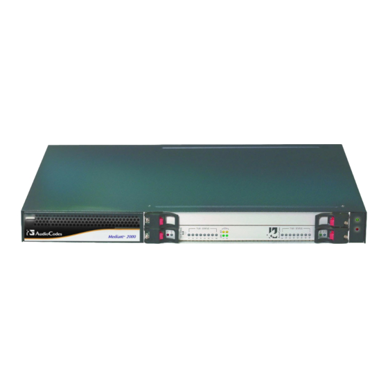
- Page 1 ™ VoIP Mediant™ Media Gateways Mediant™ 2000 MGCP, MEGACO, TPNCP User’s Manual version 5.0 Document #: LTRT-69805 June 2006...
-
Page 3: Table Of Contents
3.2 Mounting the Mediant 2000..............34 3.2.1 Mounting the Mediant 2000 on a Desktop ..........37 3.2.2 Mounting a Mediant 2000 in a 19-inch Rack ........... 37 3.3 Cabling the Mediant 2000 ...............39 3.3.1 Connecting the E1/T1 Trunk Interfaces ........... 39 3.4 Board Replacement.................45... - Page 4 Mediant 2000 5.2 Restoring Networking Parameters to their Initial State......55 Mediant 2000 Initialization & Configuration Files ...........57 6.1 Mediant 2000 Startup ................57 6.2 Boot Firmware & Operational Firmware ..........57 6.3 Using BootP/DHCP..................59 6.3.1 BootP/DHCP Server Parameters............. 59 6.3.2 Host Name Support ................. 62 6.3.3...
- Page 5 Embedded Web Server Protection & Security Mechanisms....188 8.2.2 Limiting the Embedded Web Server to Read-Only Mode ...... 189 8.2.3 Correlating PC / Mediant 2000 IP Address & Subnet Mask ....191 8.2.4 Accessing the Embedded Web Server ..........191 8.2.5 Using Internet Explorer to Access the Embedded Web Server .....
- Page 6 Mediant 2000 10 Technical Specifications - Mediant 2000............285 10.1 Mediant 2000 Selected Technical Specifications........285 11 Appendix - Individual ini File Parameters .............291 11.1 Individual ini File Parameters ...............291 11.1.1 System Parameters ................292 11.1.2 PSTN Parameters.................. 298 11.1.3 Infrastructure Parameters ..............308 11.1.4 Media Processing Parameters...............
- Page 7 User's Manual Contents 14 Appendix - RTP/RTCP Payload Types............399 14.1 Payload Types Defined in RFC 3551............399 14.2 Payload Types Not Defined in RFC 3551 ..........399 14.3 Default Dynamic Payload Types Which are Not Voice Coders..400 14.4 Default RTP/RTCP/T.38 Port Allocation ..........401 15 Appendix - DTMF, Fax &...
- Page 8 Mediant 2000 17 Appendix - CAS to Analog Mapping Protocol ..........419 17.1 ini File Configuration................422 17.2 Pulse Dial Detection ................422 17.3 ini File Configuration................422 17.4 CAS Table Configuration ..............422 18 Appendix - Security..................425 18.1 IKE and IPSec ..................426 18.1.1 IKE ......................426 18.1.2 IPSec .....................
- Page 9 23.1.2 Integrating Using the ini File ..............517 23.2 Basic Setup ....................518 23.3 Setup Example..................518 23.4 Preparing the Mediant 2000 for VLANs and Multiple IPs (MI) ....519 23.5 Verifying the VLANS and Multiple IP Settings Using the Embedded Web Server ....................521 23.6 OAM Parameters..................523...
- Page 10 Mediant 2000 24.2 Log Traps (Notifications) ..............539 24.3 Other Traps ....................540 24.4 Trap Varbinds ..................542 25 Appendix - Customizing the Web Interface ..........543 25.1 Company & Product Bar Components ..........543 25.2 Replacing the Main Corporate Logo ............544 25.2.1 Replacing the Main Corporate Logo with an Image File......544 25.2.2 Replacing the Main Corporate Logo with a Text String ......
- Page 11 User's Manual Contents List of Figures Figure 1-1: 2000 Functional Block Diagram ...................23 Figure 1-2: Typical Mediant 2000 Wireline Application ................24 Figure 2-1: 2000 Front View ........................25 Figure 2-2: 1610 Board...........................27 Figure 2-3: 1610 RTM - with Telco Connectors ..................27 Figure 2-4: 1610 Board, Front Panel View .....................28...
- Page 12 Mediant 2000 Figure 8-33: IPmedia Settings Screen ....................218 Figure 8-34: General Settings Screen....................219 Figure 8-35: Trunk Settings Screen ....................219 Figure 8-36: Q931 Layer Response Behavior Screen ................ 222 Figure 8-37: Outgoing Calls Behavior Screen..................222 Figure 8-38: Incoming Calls Behavior Screen..................223 Figure 8-39: General Call Control Behavior Screen................
- Page 13 User's Manual Contents Figure 19-3: SS7 MTP3 Node ......................452 Figure 19-4: SS7 MTP2 Tunneling...................... 453 Figure 19-5: M2UA Architecture......................468 Figure 19-6: M2TN Architecture ......................468 Figure 19-7: Protocol Architecture for MTP2 Tunneling..............469 Figure 20-1: TrunkPack Downloadable Conversion Utility R2.5.2 ............472 Figure 20-2: Call Progress Tones Screen ...................
- Page 14 Table 3-4: Table 2-4: E1/T1 Connections on each 50-pin Telco Connector..........40 Table 3-5: Mediant 2000 Rear Panel Cabling (16 Trunks, Dual AC Power) Component Descriptions .44 Table 3-6: Mediant 2000 Rear Panel Cabling (8 Trunks, DC Power) Component Descriptions ...44 Table 4-1: Software Package Contents....................50...
- Page 15 User's Manual Contents Table 7-40: Basic Service Tones Generation Package - SRVTN............150 Table 7-41: Expanded Services Tones Generation Package - XSRVTN ........... 151 Table 7-42: Basic CAS Signal/Events ....................151 Table 7-43: Basic CAS Addressing Signal/Events................151 Table 7-44: Robbed Bit Signaling Signal/Events ................152 Table 7-45: OSES Signal/Events ......................
- Page 16 Mediant 2000 Table 12-11: SigTran Interface IDs Table Parameters ............... 381 Table 12-12: SS7 MTP3 Redundancy SN Table Parameters............382 Table 12-13: NFS Servers Table Parameters ..................383 Table 13-1: Default Call Progress Tones .................... 388 Table 14-1: Payload Types Defined in RFC 3551................399 Table 14-2: Payload Types Not Defined in RFC 3551 ................
-
Page 17: Version 5.0
User's Manual Contents Table 27-1: List of Abbreviations......................557 Version 5.0 June 2006... -
Page 19: Introductory Notes
Notice This User’s Manual describes the installation and use of the Mediant 2000. Information contained in this document is believed to be accurate and reliable at the time of printing. However, due to ongoing product improvements and revisions, AudioCodes cannot guarantee the accuracy of printed material after the Date Published nor can it accept responsibility for errors or omissions. -
Page 20: Abbreviations And Terminology
(for example various networking issues). VoPLib API Reference Manual, Document # LTRT-840xx - intended for users, who wish to control the board via the AudioCodes VoPLib API (over PCI or TPNCP). This manual is a documentation browser in HTML or CHM formats (created from the VoPLib documented source files). -
Page 21: Overview Of The Mediant 2000
ISDN PRI, SigTran (M2UA, M3UA, IUA) and CAS. The Mediant 2000 incorporates up to 16 E1, T1 or J1 spans for connection, either directly to PSTN telephony trunks, or to an enterprise PBX, and two 10/100 Base-TX Ethernet ports for redundant connection to the LAN. - Page 22 Superior, high quality VoIP calls and FoIP transmissions Interchangeable IP/RTP or PSTN Endpoints VoIP packet streaming (RTP/ RTCP) per RFC 3550/3551 TPNCP (AudioCodes’ proprietary TrunkPack Network Control Protocol), MGCP (RFC 3435), MEGACO (H.248) and optional H.323 and SIP standards-based control protocols Real-time Fax over IP/T.38 with superior performance (round trip delay of up to 9...
-
Page 23: Available Configurations
Optional dual redundant AC power supply or single DC power supply Available Configurations The Mediant 2000 is offered in a variety of channel densities and rear I/O options. Most of the descriptions in this manual refer to the full capacity model (i.e., with 16 spans). -
Page 24: Typical Application Diagram
Mediant 2000 Typical Application Diagram The diagram below illustrates a typical wireline application. Figure 1-2: Typical Mediant 2000 Wireline Application User's Manual Document # LTRT-69805... -
Page 25: Hardware Equipment
The Mediant 2000 chassis’ rear cage, slot #1 - the lower slot, houses the TP-1610 RTM. Slot # 2 in the Mediant 2000 chassis’ front and rear cages optionally can be used by Customers for a CPU board. For more information on CPU board options, refer to ''Optional CPU Board'' on page 32. -
Page 26: Chassis Led Indicators
AC connection.) The TP-1610 Board The TP-1610 Board is the main component of the Mediant 2000 Gateway and is supplied within it. The TP-1610 board front panel is shown in the figure 'TP-1610 Board Front Panel View' on page 28. -
Page 27: Board Hot-Swap Support
User's Manual 2. Hardware Equipment The figure below displays the TP-1610 board. Figure 2-2: 1610 Board The figure below illustrates the TP-1610 board’s corresponding Rear Transition Module (RTM) with 50-Pin Telco Connectors. Figure 2-3: 1610 RTM - with Telco Connectors 2.2.1 Board Hot-Swap Support The TP-1610 board is hot swappable and can therefore be removed from a slot (and... -
Page 28: Tp-1610 Board Front Panel View
Mediant 2000 TP-1610 Board Front Panel View Figure 2-4: 1610 Board, Front Panel View User's Manual Document # LTRT-69805... -
Page 29: Tp-1610 Rtm Panel Diagrams
User's Manual 2. Hardware Equipment TP-1610 RTM Panel Diagrams Figure 2-5: 1610 RTM Panel with 2 Telco Connectors Version 5.0 June 2006... -
Page 30: Tp-1610 Board Panel Led Indicators
Mediant 2000 Figure 2-6: RTM Panel with 8 RJ-48c Trunk Connectors TP-1610 Board Panel LED Indicators The tables below provide the LED indicator definitions. User's Manual Document # LTRT-69805... -
Page 31: Table 2-2: Board Status Led Indicators
During normal operation, the E1/T1 bi-color LED illuminates Green for each trunk. Any other condition, either in the E1/T1 cable, in the Mediant 2000, or on the remote side, causes the E1/T1 bi-color LED to light up Red, indicating a loss due to any of the 4 signals listed and described in the table below. -
Page 32: Optional Cpu Board
45. Optional CPU Board The Mediant 2000 device features a second cPCI slot that can be optionally used for a customer's CPU board. The CPU board can be used for general applications such as a Softswitch, Application Server, etc. The following CPU boards were tested for compliancy with the Mediant 2000 Media Gateway: Sun™:... -
Page 33: Hardware Installation
The Mediant 2000 can be installed either as a desktop system or as a chassis in a standard 19-inch rack. Warning The Mediant 2000 is supplied as a sealed unit and must only be serviced by qualified service personnel. Electrical Earthing... -
Page 34: Package Contents
Ensure that, in addition to the Mediant 2000, the package includes the following items: For the dual AC power supply version of the Mediant 2000, two AC power cables are supplied; for the single AC power supply version of the Mediant 2000, one AC power cable is supplied. -
Page 35: Figure 3-2: Mediant 2000 Front Panel
User's Manual 3. Hardware Installation Figure 3-2: Mediant 2000 Front Panel Table 3-1: Mediant 2000 Front Details Item # Component Description Power LED Dual AC Power LED Screws cPCI board locking screws Latch cPCI latches TP-1610 TP-1610 cPCI board, 16-trunk configuration... -
Page 36: Figure 3-3: 2000 System Rear Connections (Rj-48C Connectors & Dc Power)
Mediant 2000 Figure 3-3: 2000 System Rear Connections (RJ-48c Connectors & DC Power) Table 3-2: Mediant 2000 Rear 8-Span Details Item # Component Description Screws cPCI board locking screws TP-1610 RTM 8-Span Rear Transition Module Ethernet Ports Two RJ-45 Ethernet Ports Interfaces... -
Page 37: Mounting The Mediant 2000 On A Desktop
Mounting the Mediant 2000 on a Desktop No brackets are required. Optionally, attach the four (supplied) anti-slide bumpers to the base of the Mediant 2000 and place it on the desktop in the position you require. 3.2.2 Mounting a Mediant 2000 in a 19-inch Rack... - Page 38 Mediant 2000 Rack Mount Safety Instructions (UL) Note: When mounting the chassis on a rack, be sure to implement the following Safety instructions: Elevated Operating Ambient - If installed in a closed or multi-unit rack assembly, the operating ambient temperature of the rack environment may be greater than room ambient.
-
Page 39: Cabling The Mediant 2000
3.3.1 Connecting the E1/T1 Trunk Interfaces The Mediant 2000 is available in a number of configurations, i.e., AC or DC, in the 16- trunk, 8-trunk, 4-trunk, 2-trunk or 1-trunk device. The 16-trunk dual AC and the 8-trunk DC configurations are illustrated here as representative products. -
Page 40: Figure 3-5: 50-Pin Female Telco Board-Mounted Connector
2 steps: Connect the E1/T1 trunk cables to the ports labeled “Trunks 1 to 8” (in the case of the 8-trunk device) on the Mediant 2000 RTM. Connect the other ends of the Trunk cables to the PBX/PSTN switch. -
Page 41: Figure 3-7: Rj-45 Ethernet Connector And Pinout
Note that for redundant operation it is recommended to connect each of the Ethernet connectors to a different Switch. When assigning an IP address to the Mediant 2000 using HTTP (refer to' Assigning an IP Address Using HTTP' on page 53), you may be required to disconnect this cable and re-cable it differently. -
Page 42: Figure 3-8: Dc Power Connector - Screw Type
3.3.1.2.2 Connecting the DC Power Supply To connect the Mediant 2000 to a DC power supply use one of these two options: DC Terminal block with a screw connection type. DC Terminal block with a crimp connection type. -
Page 43: Figure 3-9: Dc Power Connector - Crimp Type
DC power supply maintain the correct polarity (refer to the figure below). Insert the terminal block to the DC inlet located on the Mediant 2000. Figure 3-9: DC Power Connector - Crimp Type The Mediant 2000 hardware installation is now complete. -
Page 44: Figure 3-11: Rear View With Connected Cables (8 Spans And Dc)
Mediant 2000 Table 3-5: Mediant 2000 Rear Panel Cabling (16 Trunks, Dual AC Power) Component Descriptions Item # Label Component Description RTM locking screws ETHERNET Two Category 5 network cables, connected to the 2 Ethernet RJ- 45 ports TRUNKS Two 50-pin Telco connector cables, each supporting 8 trunks Protective earthing screw 100-240~1.5A... -
Page 45: Board Replacement
The Mediant 2000 Media Gateway components are hot swappable which means that they can be removed from the chassis without taking the Mediant 2000 out of service. However, currently, the Mediant 2000 is a single gateway which is configured into the network with an N+1 redundancy meaning that other gateways in the network are available to take the load in the event of a card failure. -
Page 46: Inserting Boards
Fasten the screws on the front panel of the board to secure the board to the chassis and to ensure that the board has a chassis earthing connection. Reattach the cables. (Refer to 'Cabling the Mediant 2000'.) User's Manual Document # LTRT-69805... -
Page 47: Configuring And Unlocking The Mediant 2000
3. Hardware Installation 3.4.4 Configuring and Unlocking the Mediant 2000 The Mediant 2000 should be unlocked using the element management system (EMS) employed in your system. For more information on performing graceful lock, refer to' 'Performing Graceful Lock'' on page or the user documentation accompanying the element management system (EMS) employed in your system. -
Page 49: Software Package
This software package must be installed on the host PC/machine to be used to manage the device. The software package is supplied to customers on a CD accompanying the Mediant 2000. To get started, take these basic steps: Install the software package refer to the Installing/Unzipping instructions below. -
Page 50: Unzipping When Using A Linux™/Solaris™ Operating System
Utilities AudioCodes’ utilities provide you with friendly interfaces that enhance device usability and smooth your transition to the new VoIP infrastructure. .\Utilities\DConvert Contains the TrunkPack Downloadable Construction Utility. - Page 51 VoP API Library AudioCodes’ proprietary API for controlling and managing the device. Detailed information on the VoPLibrary can be found in AudioCodes’ VoPLib API Reference Manual, Document #: LTRT-840xx and VoPLib User’s Manual, Document #: LTRT-844xx. .\VoP_API_Library\VoPLib\ Contains the VoPLib sources - cpp and h files.
-
Page 53: Getting Started
Server' on page 187. Assigning the Mediant 2000 IP Address To assign an IP address to the Mediant 2000 use one of the following methods: HTTP using a Web browser (refer to ''Assigning an IP Address Using HTTP'' on page 53). -
Page 54: Assigning An Ip Address Using Bootp
If your network doesn’t feature a default gateway, enter a dummy value in the Default Gateway IP Address field. Click the Reset button and click OK in the prompt. The Mediant 2000 applies the changes and restarts. This takes approximately 1 minute to complete. When the Mediant 2000 has finished restarting, the Ready and LAN LEDs on the front panel are lit green. -
Page 55: Restoring Networking Parameters To Their Initial State
Restoring Networking Parameters to their Initial State You can use the Reset button to restore the Mediant 2000 networking parameters to their factory default values (described in the 'Default Networking Parameters' on page 53) and to reset the username and password. -
Page 57: Mediant 2000 Initialization & Configuration Files
Auxiliary Files (refer to the 'Appendix - Auxiliary Files' on page 385) Mediant 2000 Startup The Mediant 2000's startup process begins when the Mediant 2000 is reset. The startup process ends when the operational firmware is running. The startup process includes how the Mediant 2000 obtains its IP parameters, firmware and configuration files. -
Page 58: Figure 6-1: Startup Process Diagram
The cmp file is usually burned into the Mediant 2000's non-volatile memory so that it does not need to be externally loaded each time the Mediant 2000 is reset (except when the board is controlled via PCI). -
Page 59: Using Bootp/Dhcp
Using BootP/DHCP The Mediant 2000 uses the Bootstrap Protocol (BootP) and the Dynamic Host Configuration Protocol (DHCP) to obtain its networking parameters and configuration automatically after it is reset. BootP and DHCP are also used to provide the IP address of a TFTP server on the network, and files (cmp and ini) to be loaded into memory. -
Page 60: Table 6-1: Command Line Switch Descriptions
Switch Description Burn ram.cmp in non-volatile memory. Only the cmp file (the compressed firmware file) can be burned to the Mediant 2000’s non-volatile memory. The hex file (the uncompressed firmware file) can not be burned. User's Manual Document # LTRT-69805... - Page 61 Mediant 2000. The switch only takes effect from the next reset of the Mediant 2000. Selective BootP Use -be 1 for the Mediant 2000 to send client information that can be viewed in the main screen of the BootP/TFTP Server, under column 'Client Info‘ (refer to the figure, Main Screen, with the column 'Client Info' on the extreme right).
-
Page 62: Host Name Support
DHCP request. The host name is set to ACL_nnnnnnn, where nnnnnnn is the serial number of the Mediant 2000 (the serial number is equal to the last 6 digits of the MAC address converted from Hex to decimal). The DHCP server usually registers this Host Name on the DNS server. -
Page 63: Microsoft™ Dhcp/Bootp Server
Table 6-3: Example of Vendor Specific Information Field Structure 6.3.5 Microsoft™ DHCP/BootP Server The Mediant 2000 can be configured with any BootP server, including the Microsoft™ Windows™ DHCP server, to provide the TP-1610 with an IP address and other initial parameter configurations. -
Page 64: Configuration Parameters And Files
Call Progress Tones, Voice Prompts, logo image, etc. These files contain factory-pre-configured parameter defaults when supplied with the Mediant 2000 and are stored in the Mediant 2000's non-volatile memory. The Mediant 2000 is started up initially with this default configuration. Subsequently, these files can... -
Page 65: Parameter Value Structure
User's Manual 6. Mediant 2000 Initialization & Configuration Files The ini file name must not include hyphens or spaces. Use underscores instead. The ini file can contain a number of parameters. The ini file structure supports the following parameter value constructs: Parameter = Value (refer to 'Parameter = Value Constructs'). - Page 66 Mediant 2000 The ini file should be ended with one or more empty lines. ini File Examples The example below shows a sample ini file for MGCP. [TDM BUS configuration] ; 1=aLaw 3=ulaw PCMLawSelect = 1 BaseUDPPort = 4000 [Trunk Configuration] ;...
-
Page 67: Table 6-4: Table Structure Example
MGCPCOMPATIBILITYPROFILE = 2 Note: Before loading an ini file to the Mediant 2000, make sure that the extension of the ini file saved on your PC is correct: Verify that the checkbox Hide extension for known file types (My Computer>Tools>Folder Options>View) is unchecked. - Page 68 Mediant 2000 example above, the format line is: FORMAT SS7_SIG_IF_ID_INDEX = SS7_SIG_IF_ID_VALUE, SS7_SIG_IF_ID_NAME, SS7_SIG_IF_ID_OWNER_GROUP, SS7_SIG_IF_ID_LAYER, SS7_SIG_IF_ID_NAI, SS7_SIG_M3UA_SPC • The first word MUST be "FORMAT", followed by indices field names, and after '=' sign, all data fields names should be listed.
-
Page 69: Binary Configuration File Download
The ini file to be loaded and retrieved is available with or without encoding. When an encoded ini file is downloaded to the Mediant 2000, it is retrieved as encoded from the Mediant 2000 as well. When a decoded file is downloaded to the Mediant 2000, it is retrieved as decoded from the Mediant 2000 as well. -
Page 70: Auxiliary Files
Mediant 2000 In order to decode an encoded ini file retrieved from the Mediant 2000, the user must retrieve an encoded ini file from the Mediant 2000 using the Web server (refer to "Downloading Auxiliary Files" below) and then use the DConvert utility in order to decode it. -
Page 71: Automatic Update Facility
AudioCodes can be used to construct your own file. The Call Progress Tones and User-Defined Tones file used by the Mediant 2000 is a binary file with the extension tone.dat. Only this binary tone.dat file can be loaded to a Mediant 2000. - Page 72 The Automatic Update process is entirely controlled by configuration parameters in the ini file. During the Automatic Update process, the Mediant 2000 contacts the external server and requests the latest version of a given set of URLs. An additional benefit of using HTTP (Web) servers is that configuration ini files would be downloaded only if they were modified since the last update.
-
Page 73: Backup Copies Of Ini And Auxiliary Files
RESETNOW = 1 You may modify the master_configuration.ini file (or any of the config_<MAC>.ini files) at any time. The Mediant 2000 queries for the latest version every 60 minutes, and applies the new settings immediately. For additional security, usage of HTTPS and FTPS protocols is recommended. -
Page 74: Software Upgrade Key
Mediant 2000 Note: Upgrading the Mediant 2000's firmware requires reloading the ini file and re- burning the configuration files. A Software Upgrade Key may be required if the new firmware's version is greater than that listed in the Software Upgrade Key menu (refer to ''Software Upgrade Wizard'' on page 255.). -
Page 75: Standard Control Protocols
MGCP assumes a call control architecture where the call control intelligence is outside the Mediant 2000 and handled by an external Call Agent. MGCP is a master/slave protocol, where the Mediant 2000 is expected to execute commands sent by the Call Agent. -
Page 76: Mgcp Call Agent Configuration
Agent of events occurring on one or more of the Endpoints. Notify commands can also generate signals on the Endpoints. Audit commands - These commands are used to query the Mediant 2000 about Endpoint configuration and state. This information helps in managing and controlling the Mediant 2000. -
Page 77: Mgcp Keepalive Mechanism
The KeepAlive mechanism maintains a constant connection with the Call Agent. In case of a Call Agent failure, the Mediant 2000 will enter into a disconnected state and will switch over to its redundant Call Agent. Moreover, since constant transportation is running between the Call Agent and the Mediant 2000, using the KeepAlive mechanism gives VoIP networks the ability to work with NAT machines. -
Page 78: Mgcp Fax
Mediant 2000 RTPMAP Used for dynamic payload mapping, to map the number to the coder. The format a=rtpmap: 97 G723/8000/1 Where: 97 is the payload number to be used G723 is the codec name 8000 is the clock rate (optional) - Page 79 User's Manual 7. Standard Control Protocols Table 7-1: MGCP Fax Package Gateway Mode Gateway CH 0 Call Agent Gateway CH 1 D: 2xxx NTFY 2075 200 2075 OK ACgw0@[10.4.4.129] MGCP 1.0 X: 12 O: 2580 200 17502 OK CRCX 17502 ACgw0@[10.4.4.129] MGCP I: 34 C: 1...
- Page 80 Mediant 2000 Table 7-1: MGCP Fax Package Gateway Mode Gateway CH 0 Call Agent Gateway CH 1 c=IN IP4 10.4.4.129 L: a:PCMA t=0 0 M: sendrecv m=audio 4000 RTP/AVP 8 c=IN IP4 10.4.4.129 m=audio 4010 RTP/AVP 8 a=sqn: 0 a=cdsc: 1 audio RTP/AVP 8...
-
Page 81: Fax Transport Type Setting With Local Connection Options
User's Manual 7. Standard Control Protocols Table 7-1: MGCP Fax Package Gateway Mode Gateway CH 0 Call Agent Gateway CH 1 250 17507 OK DLCX 17507 ACgw0@[10.4.4.129] MGCP DLCX 17508 250 17508 OK ACgw1@[10.4.4.129] MGCP 7.1.9 Fax Transport Type Setting with Local Connection Options In addition to the T.38 Fax package described in ''Fax Package Definition - FXR'' on page 105, the parameter, “x-faxtranstype”... -
Page 82: Sdp Usage
Mediant 2000 The feature enables the gateway to negotiate over a VBD coder used for bypass mode. That is, if we are in bypass mode, then in case a fax/modem event occurred, we will switch to the VBD coder and when the event ended, we will return to our default voice coder. -
Page 83: Table 7-3: Vbd Examples
User's Manual 7. Standard Control Protocols 2. One gpmd field for all of the coders: L: a:codec1;codec2, md/gpmd:"codec1 vbd=yes" ; "codec2 vbd=yes" 3. Reference to a specific coder if same coder appears a number of time: L: a:codec1;codec1, md/gpmd : "codec1:2 vbd=yes". (The vbd coder is the second codec1). - Page 84 Mediant 2000 Table 7-3: VBD Examples Command Expected Results a=rtpmap:99 G726-40/8000/1 a=gpmd:99 vbd=yes (All the list of given VBD codecs are used for VBD) CRCX 29630 ACgw1@[10.4.4.123] MGCP 1.0 200 29720 OK C: 1 I: 23 M: recvonly o=- 1966564099 0 IN IP4 10.4.4.123 o=- 379071889 0 IN IP4 10.4.4.123...
-
Page 85: Mgcp Profiling
7.1.12 TGCP Compatibility To use Trunking Gateway Control Protocol (TGCP) conventions, the user must set the Mediant 2000 to the TGCP profile, e.g., adding MGCPCompatibilityProfile = 32 to the Mediant 2000's ini file. The following lists the supported TGCP additions: Endpoint Naming Scheme - Supports wild card and Endpoint naming conventions. -
Page 86: Electronic Surveillance (Calea)
If the CALEA is activated on a call, and, due to lack of board resources, CALEA is not supported by the Mediant 2000, the call does not fail and appropriate error messages are issued notifying that call was established without CALEA (error codes 211-214). -
Page 87: Table 7-4: Srtp Abnf Parameter Description
SRTP implementation in DSP is limited to AES_CM_128_HMAC_SHA1_32, AES_CM_128_HMAC_SHA1_80. All other suites are ignored. While SRTP suite may hold many keys and key parameters, the Mediant 2000 supports a single key or no key parameters. Suites that are provided with many keys or keys parameters are ignored and marked as not valid. - Page 88 Mediant 2000 The fields "tag", "crypto-suite", "key-params|, and "session-params" are described below. An example of the crypto attribute for the "RTP/SAVP" transport is provided, i.e., the secure RTP extension to the Audio/Video Profile [srtp]. In the following, new lines are included for formatting reasons only:...
- Page 89 User's Manual 7. Standard Control Protocols c=IN IP4 10.4.4.129 t=0 0 m=audio 4000 RTP/AVP 8 a=rtcp-xr: a=crypto:1 AES_CM_128_HMAC_SHA1_32 inline:MKHEBFC/PMKHEB+CJfvspnkheifcZW a=crypto:2 AES_CM_128_HMAC_SHA1_80 inline:9630xvspsqnkhecZEC/8520xurolpm m=image 4002 udptl t38 Terminated side gets originated side information. CRCX 15938 ds/tr0/2@[10.4.4.129] MGCP 1.0 C: 1 L: a:PCMA M: sendrecv o=- 1147873153 0 IN IP4 10.4.4.129 c=IN IP4 10.4.4.129...
- Page 90 Mediant 2000 t=0 0 m=audio 4010 RTP/AVP 8 a=rtcp-xr: a=crypto:1 AES_CM_128_HMAC_SHA1_32 inline:EbYVSPNKNLIFC/966j030xvspmjheh m=image 4012 udptl t38 Update succeeded. 200 15940 OK LCO Only Selection of a specific package. CRCX 15963 ds/tr0/1@[10.4.4.129] MGCP 1.0 C: 1 L: a:PCMA,x-SRTP:AES_CM_128_HMAC_SHA1_32 M: recvonly 200 15963 OK I: 21 o=- 377373126 0 IN IP4 10.4.4.129...
- Page 91 User's Manual 7. Standard Control Protocols 7.1.14.5.2 Negotiation Errors • If LCO was provided with no valid SRTP suites, a 532 error will be returned. • If SDP was provided with no valid SRTP suites, a 505 error will be returned. •...
-
Page 92: Mgcp Coder Negotiation
Mediant 2000 lifetime = ["2^"] 1*(DIGIT) ; see section 5.1 for "2^" = mki-value ":" mki-length mki-value = 1*DIGIT mki-length = 1*3DIGIT ; range 1..128. srtp-session-param = kdr / "UNENCRYPTED_SRTP" / "UNENCRYPTED_SRTCP" / "UNAUTHENTICATED_SRTP" / fec-order / fec-key / wsh / srtp-session-extension = "KDR="... - Page 93 User's Manual 7. Standard Control Protocols Internal coders list – this list contains the coders supported by the gateway. LCO list – list supplied by the Call Agent. RCO list – list supplied by the remote side. Note: Refer to RFC 3435, Section 2.6, 'Use of Local Connection Options and Connection Descriptors'.
-
Page 94: Table 7-5: Mgcp Mapping Of Payload Numbers To Coders
Mediant 2000 7.1.15.4 Mapping of Payload Numbers to Coders The table below shows the default mapping between payload numbers and coders, when the dynamic payload assignment is not used. Coders are supported according to selected DSPVersion templates - DSPVersionTemplateNumber ini file parameter. -
Page 95: Supported Mgcp Packages
User's Manual 7. Standard Control Protocols Table 7-5: MGCP Mapping of Payload Numbers to Coders Coder Encoding Name Default Payload Number G.727_32_24 "X-G727_32_24" G.727_40_16 "X-G727_40_16" G.727_40_24 "X-G727_40_24" G.727_40_32 "X-G727_40_32" G.728 "G728" G.729 "G729","G.729","G729A" "GSM" GSM-EFR “GSM-EFR” NetCoder_4_8 "X-NETCODER_4_8", “NETCODER_4_8” NetCoder_5_6 "X-NETCODER_5_6",“NETCODER_5_6”... -
Page 96: Table 7-6: Generic Media Package - G
Mediant 2000 Notes for all MGCP Package tables: An x appears in this column if the event can be requested by the Call Agent. If nothing appears in this column for an event, then the event cannot be signaled on command by the Call Agent. -
Page 97: Table 7-8: Line Package - L
User's Manual 7. Standard Control Protocols Table 7-7: DTMF Package - D Symbol Definition Duration DTMF 8 DTMF 9 DTMF # DTMF * DTMF A DTMF B DTMF C DTMF D Inter-digit Timer 4 sec Wildcard, match any digit 0 to Report Failure 7.1.15.8 Line Package - L... -
Page 98: Table 7-9: Handset Emulation Package - H
Mediant 2000 Table 7-8: Line Package - L Symbol Definition Duration wt, wt1, Call waiting tones wt2,wt3,wt4 ci (ti,nu,na) Caller ID (ci(time, number, name) Time = MM/DD/HH/MN sup(addr(“digits” DTMF dialing Report Failure line side answer infinite supervision network disconnect 900 ms... -
Page 99: Table 7-10: Trunk Package - T
User's Manual 7. Standard Control Protocols Table 7-9: Handset Emulation Package - H Symbol Definition Duration/Comment Report Failure line side answer supervision infinite Network Disconnect 900 ms 7.1.15.10 Trunk Package - T Table 7-10: Trunk Package - T Symbol Definition Duration/Comment Continuity tone 2 sec... -
Page 100: Table 7-12: Generic Media Package - A
Mediant 2000 Table 7-11: PacketCable (NCS) Line Package - L Symbol Definition Duration/Comment Dial tone Fax tone Off-hook transition Flash hook On-hook transition Modem tones Message waiting indicator 16 sec Operation complete Operation failure Off-hook warning tone Time-out = infinite r0, r1, r2, r3, r4, Distinctive ringing (0...7) -
Page 101: Table 7-13: Rtp Package - R
User's Manual 7. Standard Control Protocols 7.1.15.13 RTP Package - R Table 7-13: RTP Package - R Symbol Definition Duration/Comment Continuity Tone (single or 2 sec return tone) Continuity Test (go tone, in 2 sec dual tone procedures) Media Start RTP/RTCP Timeout RTP/RTCP Timeout (rto(<timeout>,st=<start-time>)): time out - optional parameter, increase in 100 msec steps. -
Page 102: Cas Packages
Mediant 2000 NTFY 3002 ds/ds1-3/6@gw-o.whatever.net MGCP 1.0 X: 1 O: r/rto(300) Continuity Test (go tone, in dual tone procedures) and Continuity Tone (single or return tone): Continuity tone generation/detection is configuration dependent. To generate continuity tones and allow for their detection (if desired), they must be defined by... -
Page 103: Table 7-14: Mf Fgd Operator Services Package - Mo
User's Manual 7. Standard Control Protocols 7.1.15.14.1 MF FGD Operator Services Package - MO Table 7-14: MF FGD Operator Services Package - MO Code Description Event Signal Additional Info Call Answer See Notes(1) Operation Complete Operation Fail orbk Operator Ringback Reverse make busy Operator Recall Release Call... -
Page 104: Table 7-16: Isup Trunk Package - It
TO,C Time-out = 180 sec 7.1.15.16 Media Format Parameter Package - FM Supported FMTP Formats According to the Media Format Parameter Package, AudioCodes supports the following FMTP formats: L:a:codec1;codec2, fmtp:"codec1 formatX", fmtp:"codec2 formatY" L:a:codec1;codec2, fmtp:"codec1 formatX";"codec2 formatY" L:a:codec1;codec1, fmtp:"codec1 formatX"... -
Page 105: Table 7-17: Fax Package Definition - Fxr
User's Manual 7. Standard Control Protocols fmtp: “AMR mode-set=2” (bitrate=5.9) fmtp: “AMR mode-set=3” (bitrate=6.7) fmtp: “AMR mode-set=4” (bitrate=7.4) fmtp: “AMR mode-set=5” (bitrate=7.95) fmtp: “AMR mode-set=6” (bitrate=10.2) fmtp: “AMR mode-set=7” (bitrate=12.2) G.723 Family fmtp: “G723 bitrate=5.3” Low fmtp: “G723 bitrate=6.3” High fmtp: “G723 annexb=yes”... -
Page 106: Mgcp Endpoint Map
Mediant 2000 handled fax event is parameterized with one of the following: • start - device handled fax was initiated • stop - device handled fax ended normally • failure - the procedure ended abnormally No Special Fax Handling (nopfax) - The no special fax handling event is parameterized with one of the following: •... -
Page 107: Compression Coders
User's Manual 7. Standard Control Protocols with the EndpointPrefix, (a string of up to 19 characters) followed by a number representing the B-channel number in the range 0 to 31 for E1, or 1 to 24 for T1/J1. The notation is shown as: EndPointPrefix/TrunkName X/Y For example: TS/Trunk#2/31 Where, in this example, EndpointPrefix=’TS’... - Page 108 Mediant 2000 Table 7-20: Compression Coders Coder MGCP Textual Name G.726_40 "G726_40" G.727_16 "G727_16",” G727” G.727_24 "G727_24" G.727_24_16 "G727_24_16" G.727_32 "G727_32" G.727_32_16 "G727_32_16" G.727_32_24 "G727_32_24" G.727_40_16 "G727_40_16" G.727_40_24 "G727_40_24" G.727_40_32 "G727_40_32" G.728 "G728" G.729 "G729","G.729","G729A" "GSM" GSM-EFR “GSM-EFR” NetCoder_4_8 "X-NETCODER", “NETCODER_4_8”...
-
Page 109: Stun - Simple Traversal Of User Datagram Protocol In Mgcp
7.1.18 STUN - Simple Traversal of User Datagram Protocol in MGCP An AudioCodes Gateway residing in a Local Area Network can discover the presence and types of NATs (Network Address Translator) and firewalls between it and the public internet using the STUN (Simple Traversal of User Datagram) protocol as described in RFC 3489. -
Page 110: Rtcp Extended Reports (Rtcp-Xr) Voip Metrics Data
Mediant 2000 2 – File printouts only. 3 – syslog & file printouts Syslog output Example: 11:35:52.636 : 10.4.4.125 : NOTICE : MGCP_CALL_STATISTICS: Endpoint Name: ds/tr0/1, Connection deleted by Call Agent, Coder: PCMU, ConnectionID: 22, CallId: 1, Call duration: 120 seconds, Local RTP port: 4000, Remote RTP address: 10.4.4.125 port 4010,... - Page 111 User's Manual 7. Standard Control Protocols Table 7-21: RTCP XR Example Flow Gateway CH 0 Call Agent Gateway CH 1 Acgw0@[10.11.10.215] MGCP 1.0 TGCP 1.0 C: 1234 L: p:20 , a:PCMU , xrm/mcr:on M: recvonly 200 4390 OK I: 25 o=- 1329622418 0 IN IP4 10.11.10.215 c=IN IP4 10.11.10.215...
- Page 112 Mediant 2000 Table 7-21: RTCP XR Example Flow Gateway CH 0 Call Agent Gateway CH 1 I: 26 o=- 1509771038 0 IN IP4 10.11.10.215 c=IN IP4 10.11.10.215 t=0 0 m=audio 4010 RTP/AVP 0 a=rtcp-xr:voip-metrics m=image 4012 udptl t38 ← MDCX 4392 Acgw0@[10.11.10.215] MGCP...
- Page 113 User's Manual 7. Standard Control Protocols Table 7-21: RTCP XR Example Flow Gateway CH 0 Call Agent Gateway CH 1 ← AUCX 17374 Acgw0@[10.11.10.215] MGCP 1.0 TGCP 1.0 I: 27 F: XRM/RVM 200 17374 OK XRM/RVM: NLR=0, JDR=0, BLD=0, GLD=0, BD=0, GD=131, RTD=0, ESD=90, SL=127, NL=127, RERL=127, GMN=16,...
-
Page 114: Controlling Jitter Buffer Settings With Mgcp
MDCX command, at the Local Connection Options line only (L: line). The syntax used is the AudioCodes proprietary syntax and hence has the prefix of ‘x-‘. If MGCP does not use these settings, as described above, the connection will be opened with the values set in the ini file. -
Page 115: Megaco (Media Gateway Control) Protocol
Mediant 2000 and handled by an external Media Gateway Controller (MGC). MEGACO is a master/slave protocol, where the Mediant 2000 is expected to execute commands sent by the Call Agent (another name for MGC). -
Page 116: Operation
Notify command - The Notify command is used by the Mediant 2000 to inform the Call Agent of events occurring on one of the Terminations. -
Page 117: Setting Megaco Call Agent Ip Address And Port
The first Call Agent in the list is the primary one. In the case of a loss of connection, the Mediant 2000 tries to connect with the next on the list, and it continues trying until one of the Call Agents accepts the registration request. If the current connection is with a secondary MGC, the Mediant 2000 starts again from the primary MGC. -
Page 118: Table 7-22: General Signal Combination Options
Mediant 2000 7.2.2.6 Support of DiffServ Capabilities The DiffServ value of the IP header can be set for both the control path and the media path. The range of the DiffServ parameter is between 0 and 63. It enables routers to differentiate between different streams. -
Page 119: Table 7-23: Signal Combination Options For Cas Support
User's Manual 7. Standard Control Protocols Table 7-22: General Signal Combination Options Group 1 Notes Group 2 Notes andisp/* (cpSignal) Only when analog gb/* (3G) board aasb/* (cpSignal) Including all the bt/* (3G) inheriting packages nttrk/* (cpSignal) ctyp/* Table 7-23: Signal Combination Options for CAS Support Group 1 Notes Group 2... - Page 120 CPT file IDs, refer to the column, Map to CPT File of the table, ''Generic Media Package - G'' on page 96. When a CPT file is missing, the Mediant 2000 defines default values only for the following signals:...
-
Page 121: Cas Protocols Support In Megaco
User's Manual 7. Standard Control Protocols The mediation is created with a simple MEGACO ADD command, with two ephemeral terminations, as shown in the following example: MEGACO/1 [10.10.0.70]; Connect the streams, Transaction = 2 { Context = $ { Add = Media { LocalControl { Mode = SendReceive,... - Page 122 Note that even though the re-answer timer is controlled by the MGC, the Mediant 2000 still keeps its own timer (currently hard-coded to be 256 seconds), so that it does not get stuck in case of command loss.
-
Page 123: Figure 7-1: Megaco-R2 Call Start Flow Diagram
User's Manual 7. Standard Control Protocols Figure 7-1: MEGACO-R2 Call Start Flow Diagram Call Start MFCR2 H.248 H.248 MFCR2 Call Originator Outgoing MG Incoming MG Call Terminator MODIFY(E=11{bcas/sz}) MODIFY(E=11{bcas/sz}) Seizure NOTIFY(OE=11{bcas/sz}) MODIFY(SG{bcas/sza}, E=22{icasc/addr}) Seizure Ack MFCR2 ADDRESS NOTIFY(OE=22{icasc/addr {di=’xxxxx’, si=’xxxxxx’, sc1=NNPS, sc2=NNPS}}) MODIFY(SG{bcas/sz}, E=33{bcas/sza}) -
Page 124: Figure 7-2: Megaco-R2 Call Disconnect Flow Diagram
Mediant 2000 Figure 7-2: MEGACO-R2 Call Disconnect Flow Diagram Terminator Disconnects MFCR2 H.248 H.248 MFCR2 Outgoing MG Incoming MG Clear back NOTIFY(OE=77{icas/cb}) Wait for Disconnect timer MODIFY(SG{icas/cb}, E=88{icas/cf}) Clear back Clear forward NOTIFY(OE=88{icas/cf}) MODIFY(SG{ibcas/cf}, E=99{icas/rlg}) Clear forward Release guard NOTIFY(OE=99{icas/rlg}) - Page 125 User's Manual 7. Standard Control Protocols 7.2.2.11.2 E911 Support in MEGACO The following attributes distinguish the E911 trunk: There are only outgoing calls. The 911 operator never calls any number. The 911 operator may hold the call so that the caller can not disconnect it. Even if the caller closes the call, the operator may ring back.
-
Page 126: Figure 7-3: Megaco-911 Call Start Flow Diagram
Mediant 2000 Figure 7-3: MEGACO-911 Call Start Flow Diagram CAMA Type to 911 switch With Operator Hold PSTN/PBX MEGACO Idle (ON_HOOK) Idle (ON_HOOK) Modify=gws0c1{ signals{bcas/sz}} psCASSeizure() OFF-HOOK Wink (140-290msec) EV_SEIZE_ACK Notify=gws0c1{bcas/sza} Modify=gws0c1{ signals{bcasaddr/addr{ ds=”A911E”, ac=MF}}, PCIIFDial (to DSP) Events=1{g/sc}} Send address Note that MEGACO has no knowledge about the type of the address sent to it. -
Page 127: Figure 7-4: Megaco-911 Operator Ringback Flow Diagram
User's Manual 7. Standard Control Protocols Figure 7-4: MEGACO-911 Operator Ringback Flow Diagram CAMA Type to 911 switch Disconnect with Operator RingBack PSTN/PBX MEGACO Call In Progress Modify=gws0c1{ signals{bcas/idle}} psCASDisconnectCall() Idle (ON_HOOK) Flash Hook EV_PSTN_FLASH_HOOK {OR} Notify=gws0c1{rbs/pson} {OR} Ringback - ST’’’ or 5 FlashHook {OR} EV_PSTN_OPERATOR_SERVICE Notify=gws0c1{oses/rgbk}... -
Page 128: Silence Suppression Support
RFC 3108 (SDP for ATM). However, as parsers ignore fields they do not recognize, it is legal to use it for IP also, assuming that the call manager is capable of doing it. 4. In all other cases, the Mediant 2000 default value is used. The table below summarizes the operation of silence suppression:... -
Page 129: Digits Collection Support
User's Manual 7. Standard Control Protocols Table 7-24: Silence Suppression Operation CONFIG G.711 G.723 G.729 Setting ON only if: ON only if: ON only if: - a=silencesupp:on - a=silencesupp:on a=silencesupp:on - payload 13 was - remote SDP does not contain - remote SDP does not contain offered on both sides the line... -
Page 130: Sdp Support In Megaco
Mediant 2000 for this feature, is the VoIP metrics report block (Block 7). This block provides metrics for monitoring VoIP calls. The MEGACO ITU standard H.248.30 defines two packages to configure the RTCP- XR and report the statistics: RTCPXR and XRBM. -
Page 131: Sdp Support Profiling
User's Manual 7. Standard Control Protocols Used for dynamic payload mapping, to map the number to the coder. The format a=rtpmap: 97 G723/8000/1 Where: 97 is the payload number to be used G723 is the encoding name 8000 is the clock rate (optional) 1 is the number of channels (optional) FMTP Defines the dynamic payload mapping for the session. -
Page 132: Support Of Asymmetric Tx/Rx Payloads
Mediant 2000 m=audio $ $ $ a=ptime:$ The reply is a list of all supported coders. 7.2.4.2.1 Support of Asymmetric Tx/Rx Payloads In the MEGACO commands, up to two SDP sessions are received. One SDP session for the local side and the another SDP session for the remote side. Each SDP can contain a different definition of the payloads to be used for the same coder. - Page 133 User's Manual 7. Standard Control Protocols c=IN IP4 10.4.4.46 a=sqn: 0 a=cdsc: 1 image udptl t38 a=cpar: a=T38FaxMaxBuffer:1024 a=cpar: a=T38FaxMaxDatagram:238 m=audio 4010 RTP/AVP 0 a=ptime:20 a=silencesupp:off - - - - }}}}} In this case, the local was requested to use both audio and image, but the remote supports only the audio.
- Page 134 Transparent) was added to the SDP according to the following rules: If the Call Manager wants this call to support T.38, it should send an additional line in the local SDP to the Mediant 2000, as in the following example: c= IN IP4 $...
-
Page 135: Support Of Rfc
The 'm=image' line, however, is mandatory, and should appear in the identical format to the above. The Mediant 2000 returns a fully specified line with the local port used for the T.38. Fax redundancy can be requested by including the following attribute line after... -
Page 136: Media Encryption (Srtp) Using Rfc
7.2.4.7 Media Encryption (SRTP) using RFC 3711 SRTP (RFC 3711) details the media encryption standard. The Mediant 2000 partially implements it. RFC 3711 defines a new media profile “RTP/SAVP” for use in secured streams. (The non-secured profile is “RTP/AVP”). - Page 137 AES_CM_128_HMAC_SHA1_32, AES_CM_128_HMAC_SHA1_80. All other suites are ignored. The SRTP suite may hold many keys and key parameters. The Mediant 2000 supports a single key and no key parameters, suites that are provided with many keys or key parameters are ignored, and marked as not valid. A suite that contains extra parameters is rejected even if it is a suite that is supported.
- Page 138 Mediant 2000 a=crypto:1 AES_CM_128_HMAC_SHA1_32 inline:MKHEBFC/PMKHEB+CJfvspnkheifcZW a=crypto:2 AES_CM_128_HMAC_SHA1_80 inline:9630xvspsqnkhecZEC/8520xurolpm crypto-suite – If the crypto suite is under specified, the gateway may chose one of the supported suites. In this case, however, the key params field should also exist and contain ‘$’. The answer to ‘a=crypto:1 $ $’ is, for example:...
- Page 139 User's Manual 7. Standard Control Protocols c=IN IP4 10.4.4.46 m=audio 4000 RTP/SAVP 0 a=crypto:1 AES_CM_128_HMAC_SHA1_32 inline:MKHEBFC/PMKHEB+CJfvspnkheifcZW a=crypto:2 AES_CM_128_HMAC_SHA1_80 inline:9630xvspsqnkhecZEC/8520xurolpm a=ptime:20 }}}}} Simple Offerer for Both Secured and Non-Secured Connection In this example, the call manager sends an under specified SDP, but this time requests both secured and non-secured connections.
- Page 140 Mediant 2000 The MGC sends: MEGACO/1 [10.2.1.228]:2944 Transaction = 3 { Context = $ { Add = $ {Media {LocalControl { Mode = Receiveonly}, Local { c=IN IP4 $ m=audio $ RTP/SAVP 0 a=crypto:1 $ $ a=ptime:20 }}}}} The Gateway answers: MEGACO/1 [10.4.4.46]:2944...
- Page 141 User's Manual 7. Standard Control Protocols C = 4 { A = GWRTP/4 {M {O { MO = Receiveonly}, c=IN IP4 10.4.4.46 m=audio 4030 RTP/SAVP 0 a=crypto:1 AES_CM_128_HMAC_SHA1_32 inline:MKHEBFC/PMKHEB+CJfvspnkheifcZW a=ptime:20 }}}}} Answerer – Local Parameters Not Defined In this example, the MGC sends the basic SDP to the local side and the offered data from the remote side.
-
Page 142: Mapping Payload Numbers To Coders
The table below shows the default mapping between payload numbers and coders when the dynamic payload assignment is not used. Note that this is a general table and only the DSP template that is loaded to a Mediant 2000 defines which coder is supported on this Mediant 2000. - Page 143 User's Manual 7. Standard Control Protocols Table 7-25: Table 32: MEGACO Mapping Payload Numbers to Coders Default Payload Encoding Name Coder Number "X-G727-32" G727_32 "X-G727-40-16" G727_40_16 "X-G727-40-24" G727_40_24 "X-G727-40-32" G727_40_32 "X-NETCODER" NetCoder_4_8 "X-NETCODER" NetCoder_5_6 "X-NETCODER" NetCoder_6_4 "X-NETCODER" NetCoder_7_2 "X-NETCODER" NetCoder_8 "X-NETCODER"...
-
Page 144: Supported Megaco Packages
Comfort Noise Note: When using dynamic payloads, do not use the Mediant 2000 default payloads for RFC 2833 (96) and RFC 2198 (104). If these values must be used, the default values for the two RFCs should be changed in the ini file. -
Page 145: Table 7-27: Base Root Package - Root
User's Manual 7. Standard Control Protocols BR signal: The Brief signal event has a short, known duration. Duration: Specifies the duration of TO signals. The specified number is used only if no other duration is given in the command or in the CPT file. 7.2.6.2 Base Root Package - ROOT Table 7-27: Base Root Package - ROOT... -
Page 146: Table 7-30: Dtmf Generator Package - Dg
Mediant 2000 7.2.6.5 DTMF Generator Package - DG (Extends ToneGen) Table 7-30: DTMF Generator Package - DG Symbol Definition Type Duration DTMF 0 Signal DTMF 1 Signal DTMF 2 Signal DTMF 3 Signal DTMF 4 Signal DTMF 5 Signal DTMF 6... -
Page 147: Table 7-32: Call Progress Tones Generator Package - Cg
User's Manual 7. Standard Control Protocols Table 7-31: DTMF Detection Package - DD Symbol Definition Type DTMF 5 Event DTMF 6 Event DTMF 7 Event DTMF 8 Event DTMF 9 Event DTMF * Event DTMF # Event DTMF A Event DTMF B Event DTMF C... -
Page 148: Table 7-33: Call Progress Tones Detection Package - Cd
Mediant 2000 7.2.6.8 Call Progress Tones Detection Package - CD (Extends ToneDet) Table 7-33: Call Progress Tones Detection Package - CD Symbol Definition Type Dial tone Event Ringing tone Event Busy tone Event Congestion tone Event Special Information tone Event... -
Page 149: Table 7-36: Rtp Package - Rtp
User's Manual 7. Standard Control Protocols Table 7-35: Network Package - NT Symbol Definition Type netfail Network failure Event qualert Quality alert - Not supported Event Termination's InContext duration Statistics Octets sent Statistics Octets received Statistics 7.2.6.11 RTP Package - RTP (Extends - NT) Table 7-36: RTP Package - RTP Symbol Definition... -
Page 150: Table 7-38: Generic Announcement Package
Mediant 2000 7.2.6.13 Generic Announcement Package - AN Table 7-38: Generic Announcement Package Symbol Definition Type Supported Parameters Initiates the play of a fixed Signal An - Announcement number announcement Di - The direction of the announcement Noc - Number of cycles... -
Page 151: Table 7-41: Expanded Services Tones Generation Package - Xsrvtn
User's Manual 7. Standard Control Protocols 7.2.6.16 Expanded Services Tones Generation Package - XSRVTN (Extends - ToneGen) Table 7-41: Expanded Services Tones Generation Package - XSRVTN Symbol Definition Type Duration Map to CPT File xferdt Call Transfer Dial Signal 180 sec Tone Call Forward Tone Signal... -
Page 152: Table 7-44: Robbed Bit Signaling Signal/Events
Mediant 2000 7.2.6.19 Robbed Bit Signaling Package - RBS Table 7-44: Robbed Bit Signaling Signal/Events Symbol Definition Type Duration Map to CPT File Symbol psoff Pulse Off- Event None hook pson Pulse On- Event None hook rbsfail RBS failure Event None 7.2.6.20... -
Page 153: Table 7-47: Cas Blocking Signal/Events
User's Manual 7. Standard Control Protocols 7.2.6.22 CAS Blocking Package - CASBLK Table 7-47: CAS Blocking Signal/Events Symbol Definition Type Duration Map to CPT File Symbol Seizure Signal/Event None ublk Answer Event None 7.2.6.23 International CAS compelled Package - ICASC Table 7-48: ICASC Signal/Events Table Symbol Definition... -
Page 154: Table 7-50: Mf Generator Package - Mfg
Mediant 2000 Table 7-49: MF Generator Package - MFG Symbol Definition Type Duration MF 8 Signal MF 9 Signal MF A Signal MF B Signal MF C Signal MF D Signal MF E Signal MF F Signal MF G Signal... -
Page 155: Table 7-51: Inactivity Timer Package - It
User's Manual 7. Standard Control Protocols Table 7-50: MF Generator Package - MFG Symbol Definition Type MF F Event MF G Event MF H Event 7.2.6.26 Inactivity Timer Package - IT Table 7-51: Inactivity Timer Package - IT Symbol Definition Type Detects that inactivity timer has Event... -
Page 156: Table 7-53: Call Type Discrimination Package - Ctyp
Mediant 2000 7.2.6.28 Call Type Discrimination Package - CTYP Table 7-53: Call Type Discrimination Package - CTYP Symbol Definition Type dtone Discriminating tone detected Event 7.2.6.29 IP Fax Package - IPFAX Table 7-54: IP Fax Package - IPFAX Symbol Definition... -
Page 157: Table 7-57: Rtcp-Xr-Base Package - Rtcpxr
User's Manual 7. Standard Control Protocols 7.2.6.32 RTCP-XR-BASE Package - RTCPXR (Extends - RTP) Table 7-57: RTCP-XR-BASE Package - RTCPXR Symbol Definition Type Packet loss concealment type Property nplr Network packet loss rate Statistics Jitter buffer Discard Rate Statistics RTCP RoundTrip Delay Statistics End System Delay Statistics... -
Page 158: Megaco Profiling
In the serviceChange request, the Timestamp parameter is omitted. • The audit command on ROOT termination with packages descriptor returns the total supported packages for the Mediant 2000. • The default packetization period (ptime) for the transparent coder is 10 milliseconds. -
Page 159: Megaco Termination Naming
- 'RTP/' for RTP terminations and 'ATM/' for ATM terminations. So assuming that the Mediant 2000 name is 'gw', if the first ephemeral Termination is of RTP type, it is called 'gwRTP/1', and if it is of ATM type, it is called 'gwATM/1'. -
Page 160: Backward Compatibility
PSTN Interface - mapping Trunk/B-channel pairs to Endpoints is hardware-specific (refer to the table, ''MEGACO EndPoint Names'' on page 161.) Note that the number of supported terminations per Mediant 2000 is equal to the channel density of the Mediant 2000. -
Page 161: Table 7-61: Megaco Endpoint Names
User's Manual 7. Standard Control Protocols Table 7-61: MEGACO Endpoint Names T1/J1 - CAS E1 - PRI/CAS E1 - T1/J1 - Endpoint Name E1 - Transparent Transparent 62 T1/J1 - PRI Transparent Acgw/T0/C1 Trunk#0/TS1 Trunk#0/TS1 Trunk#0/TS1 Trunk#0/TS1 Acgw/T0/C2 Trunk#0/TS2 Trunk#0/TS2 Trunk#0/TS2 Trunk#0/TS2 Acgw/T0/C3... - Page 162 Mediant 2000 Table 7-61: MEGACO Endpoint Names T1/J1 - CAS E1 - PRI/CAS E1 - T1/J1 - Endpoint Name E1 - Transparent Transparent 62 T1/J1 - PRI Transparent Acgw/T0/C30 Trunk#0/TS30 Trunk#0/TS30 Acgw/T0/C31 Trunk#0/TS31 Trunk#0/TS31 Acgw/T1/C1 Trunk#1/TS1 Trunk#1/TS1 Trunk#1/TS1 Trunk#1/TS1 Acgw/T1/C3...
- Page 163 User's Manual 7. Standard Control Protocols Table 7-61: MEGACO Endpoint Names T1/J1 - CAS E1 - PRI/CAS E1 - T1/J1 - Endpoint Name E1 - Transparent Transparent 62 T1/J1 - PRI Transparent Acgw/T1/C29 Trunk#1/TS29 Trunk#1/TS29 Acgw/T1/C30 Trunk#1/TS30 Acgw/T1/C31 Trunk#1/TS31 Version 5.0 June 2006...
-
Page 165: Mediant 2000 Management
User's Manual 8. Mediant 2000 Management Mediant 2000 Management Two types of Mediant 2000 management are detailed in this section: SNMP-Based Client Program - Refer to "Using SNMP" below Web interface - Refer to ''Embedded Web Server'' on page Using SNMP Simple Network Management Protocol (SNMP) is a standards-based network control protocol for managing elements in a network. -
Page 166: Snmp Mib Objects
Mediant 2000 network manager of a problem apart from the polling of the device. Each of these message types fulfills a particular requirement of network managers: Get Request - Specific values can be fetched via the "get" request to determine the performance and state of the device. -
Page 167: Carrier-Grade Alarm System
User's Manual 8. Mediant 2000 Management "Discrete" objects, this instance number is zero. For "Table" objects, this instance number is the index into the SNMP table. SNMP tables are special types of SNMP objects, which allow parallel arrays of information to be supported. Tables are distinguished from scalar objects, such that tables can grow without bounds. -
Page 168: Cold Start Trap
8.1.3 Cold Start Trap Mediant 2000 technology supports a cold start trap to indicate that the unit is starting. This allows the EMS to synchronize its view of the unit's active alarms. In fact, two different traps are sent at start-up: The standard coldStart trap - iso(1).org(3).dod(6).internet(1). -
Page 169: Total Counters
User's Manual 8. Mediant 2000 Management iso(1).org(3).dod(6).internet(1).private(4).enterprises(1).AudioCodes(5003).acPer formance(10). There are two formats of Performance Monitoring MIBs: Older Format Each MIB is made up of a list of single MIB objects, each relating to a separate attribute within a gauge or counter. All counters and gauges give the current time value only. -
Page 170: Trunkpack-Vop Series Supported Mibs
The inverse tables are NOT supported. Notification Log MIB - This standard MIB (RFC 3014 - iso.org.dod.internet.mgmt.mib-2) is supported as part of AudioCodes' implementation of Carrier Grade Alarms. Alarm MIB - This IETF MIB (RFC 3877) is supported as part of the implementation of Carrier Grade Alarms. - Page 171 User's Manual 8. Mediant 2000 Management RTCP-XR – This MIB (RFC) implements the following partial support: • The rtcpXrCallQualityTable is fully supported. • In the rtcpXrHistoryTable, support of the RCQ objects is provided only with no more than 3 intervals, 15 minutes long each.
- Page 172 Mediant 2000 • acTrap Each AudioCodes proprietary MIBs contain a Configuration subtree, for configuring the related parameters. In some, there also are Status and Action subtrees. acControl MIB acMedia MIB acSystem MIB acSS7 MIB AcAlarm - This is a proprietary carrier-grade alarm MIB. It is a simpler implementation of the notificationLogMIB and the IETF suggested alarmMIB (both also supported in all AudioCodes boards).
- Page 173 • acKeepAlive – part of the NAT traversal mechanism. If the STUN application in the Mediant 2000 detects a NAT then this trap is sent out on a regular time laps - 9/10 of the acSysSTUNBindingLifeTime object. The AdditionalInfo1 varbind has the MAC address of the Mediant 2000.
-
Page 174: Snmp Interface Details
Mediant 2000 state of the link becomes -SERVICE or OFFLINE. • acSS7LinkInhibitStateChangeAlarm - This alarm is raised if the SS7 link becomes inhibited (local or remote). The alarm is cleared when the link becomes uninhibited - local AND remote. Note that this alarm is raised for any change in the remote or local inhibition status. -
Page 175: Table 8-1: Snmp Predefined Groups
User's Manual 8. Mediant 2000 Management Use SNMP encoded over IPSec. For more details, refer to the Appendix, Security Use some combinations of the above For ini file encoding, refer to the Appendix 'Utilities' on page 471. 8.1.5.1 SNMP Community Names By default, the board uses a single, read-only community string of "public"... - Page 176 Mediant 2000 To delete the read-only community string, v2user, take these 3 steps: If v2user is being used as the trap community string, follow the procedure for changing the trap community string. (See below.) Delete the snmpCommunityTable row with CommunityName v2user.
-
Page 177: Table 8-2: Snmpv3 Security Levels
User's Manual 8. Mediant 2000 Management Modify the field in the appropriate row of the SecurityName snmpTargetParamsTable. Remove the row from the vacmSecurityToGroupTable with SecurityName=the old trap community string. 8.1.5.2 SNMPv3 USM Users One can configure up to 10 SNMPv3 USM users. Each user can be configured for one... -
Page 178: Table 8-4: Snmpv3 Table Columns Description
Mediant 2000 The table columns are described below. Table 8-4: SNMPv3 Table Columns Description Parameter Description/ Default Note Modification Row number This is the table index. Its valid range is 0 to 9. SNMPUsers_Username Name of the v3 user. Must be unique. The maximum length is 32 characters. - Page 179 User's Manual 8. Mediant 2000 Management 8.1.5.4 Configuration of SNMPv3 users via SNMP To configure SNMPv3 users, the EM must use the standard snmpUsmMIB and the snmpVacmMIB. To add a read-only, noAuthNoPriv SNMPv3 user, v3user, take these 3 steps: Note: A row with the same security level (noAuthNoPriv) must already exist in the usmUserTable.
-
Page 180: Trusted Managers
Mediant 2000 Delete the vacmSecurityToGroupTable row for SecurityName v3admin1, GroupName ReadWriteGroup1 and SecurityModel usm. Delete the row in the usmUserTable for v3admin1 8.1.5.5 Trusted Managers By default, the agent accepts get and set requests from any IP address, as long as the correct community string is used in the request. -
Page 181: Snmp Ports
User's Manual 8. Mediant 2000 Management Set the value of the TransportTag field on each non-TrapGroup row in the snmpCommunityTable to MGR. To add a subsequent Trusted Manager, take these 2 steps: This procedure assumes that there is at least one configured read-write community. -
Page 182: Multiple Snmp Trap Destinations
Mediant 2000 8.1.5.7 Multiple SNMP Trap Destinations An agent can send traps to up to five managers. For each manager the user needs to set the manager IP and trap receiving port along with enabling the sending to that manager. - Page 183 User's Manual 8. Mediant 2000 Management ; block. Supply an IP address and if necessary, change the port ; number. ; To delete a trap destination, set ISUSED to 0. ;SNMPMANAGERTABLEIP_0= ;SNMPMANAGERTRAPPORT_0=162 ;SNMPMANAGERISUSED_0=1 ;SNMPMANAGERTRAPSENDINGENABLE_0=1 ;SNMPMANAGERTRAPUSER_0=’’ ;SNMPMANAGERTABLEIP_1= ;SNMPMANAGERTRAPPORT_1=162 ;SNMPMANAGERISUSED_1=1 ;SNMPMANAGERTRAPSENDINGENABLE_1=1 ;SNMPMANAGERTRAPUSER_1=’’...
- Page 184 Mediant 2000 snmpManagerIP Note: Currently, any trap destinations created via SNMP are associated with the trap community string and are sent in the SNMPv2 format. When snmpManagerIsUsed is set to zero (not used) the other three parameters are set to zero. (The intent is to have them set to the default value, which means TrapPort is to be set to 162.
-
Page 185: Dual Module Interface
User's Manual 8. Mediant 2000 Management To delete a trap destination, take these 2 steps: Remove the appropriate row from the snmpTargetAddrTable. If this is the last trap destination associated with this user and security level, you could also delete the appropriate row from the snmpTargetParamsTable. -
Page 186: Snmp Nat Traversal
Mediant 2000 8.1.7 SNMP NAT Traversal A NAT placed between a Mediant 2000 and the element manager calls for traversal solutions: Trap source port – all traps are sent out from the SNMP port (default – 161). A manager receiving these traps can use the binding information (in the UDP layer) to traverse the NAT back to the device. -
Page 187: Embedded Web Server
Embedded Web Server The Mediant 2000 boards and modules contain an Embedded Web Server to be used for device configuration and for run-time monitoring. The Embedded Web Server enables users equipped with any standard Web-browsing application such as Microsoft™... -
Page 188: Embedded Web Server Protection & Security Mechanisms
Mediant 2000 Load the ini file (refer to ''Software Upgrade Wizard'' on page 255) Load the CMP, Voice Prompt, Prerecorded Tones, Coder Table, CPT and CAS Files (refer to ''Auxiliary Files Download'' on page 261.) 8.2.1 Embedded Web Server Protection & Security Mechanisms... -
Page 189: Limiting The Embedded Web Server To Read-Only Mode
Server, either by modifying parameters on the various pages or by loading a text configuration file - an ini file to the Mediant 2000. Users can limit the Web Server to read-only mode by changing the default of ini file parameter DisableWebConfig. -
Page 190: Disabling The Embedded Web Server
Mediant 2000 8.2.2.1 Limiting the Embedded Web Server to Read-Only Mode Users can limit the Web Server to read-only mode by changing the default of ini file parameter DisableWebConfig. Use the read-only mode feature as a security measure. This security level provides protection against unauthorized access (such as Internet hacker attacks), particularly important to users without a firewall. -
Page 191: Correlating Pc / Mediant 2000 Ip Address & Subnet Mask
Before using the Web browser to access the Mediant 2000’s Embedded Web Server, change the PC’s IP address and Subnet Mask to correspond with the Mediant 2000’s factory default IP address and Subnet Mask shown in the table below. For details on changing the IP address and Subnet Mask, refer to the Help information provided by the Operating System used. -
Page 192: Using Internet Explorer To Access The Embedded Web Server
Mediant 2000 Note: The browser must be Java-script enabled. If java-script is disabled, a message box with notification of this is displayed. Specify the IP address of the device in the browser's URL field (e.g., http://10.1.229.17 or https://10.1.229.17 for an SSL secure link). The Embedded Web Server Enter Network Password screen appears. -
Page 193: Getting Acquainted With The Web Interface
User's Manual 8. Mediant 2000 Management Restart the browser. This fixes any issues related to domain use logon policy. 8.2.6 Getting Acquainted with the Web Interface 8.2.6.1 About the Web Interface Screen The figure below is an example of the General layout of the Web Interface screen. -
Page 194: Figure 8-3: Trunk And Channel Status Screen
Mediant 2000 In the Web browser's Address field, type the gateway IP address. The Gateway Home Page appears displaying the Trunk and Channel Status screen. The screen is Read-only. Figure 8-3: Trunk and Channel Status Screen The number of trunks and channels that appear on the screen depends of the system configuration. -
Page 195: Search Engine
User's Manual 8. Mediant 2000 Management Table 8-9: Trunk and Channel Status Color Indicator Key Trunk Channel LOS/LOF Alarm Black Non-Voice Blue AIS Alarm Orange D-Channel Alarm To display a screen with a summary of parameter information relevant to a channel, click on the channel. -
Page 196: Figure 8-4: Web Search Results
Mediant 2000 To search for an ini file parameter, take this step: In the Search Engine field, type any sub-string from the full ini parameter name and click the Search button or press Enter). The searched results screen appears. Figure 8-4: Web Search Results... -
Page 197: Figure 8-5: Web Search Link Display Results
User's Manual 8. Mediant 2000 Management To go to the screen containing the desired parameter, take this step: Click the link of the desired parameter. The screen containing the parameter appears and displays the desired parameter highlighted in green. Figure 8-5: Web Search Link Display Results 8.2.6.1.4... -
Page 198: Figure 8-7: Update Port Info Text Field
Mediant 2000 Select the Update Port Info option. A text field and the ApplyPortInfo button appears. Figure 8-7: Update Port Info Text Field Type in the desired text for the Port Information and click the ApplyPortInfo button. the information is saved. This information is displayed as a tooltip when you place the mouse curser over the configured trunk or channel. -
Page 199: Figure 8-9: Rtp/Rtcp Information Screen
Figure 8-10: Voice Information Screen 8.2.6.2 Quick Setup To quickly setup the Mediant 2000, take these 16 steps: Access the Web Server Interface (refer to ''Accessing the Embedded Web Server'' on page 191.) Enter the Administrator level Username (default: Admin) and Password (default: Admin). -
Page 200: Figure 8-11: Quick Setup Screen
IP Address settings, or you can enable the DHCP negotiation to start after reset. Refer to ''Correlating PC /Mediant 2000 IP Address & Subnet Mask'' on page 191. For the Default Gateway Address, DNS Primary Server IP and DNS Secondary Server IP fields, enter appropriate addresses. -
Page 201: Protocol Management
In the Call Agent Domain Name field, when using the DNS server option, enter the Domain Name of the Call Agent operating with the Mediant 2000. The DNS server automatically detects the Call Agent’s IP address from the Domain Name. -
Page 202: Figure 8-12: Protocol Management Screen
Note: Changing the protocol type requires a device reset. When you have completed configuring the desired parameters, the Mediant 2000 must be reset using the Reset screen (refer to ''Reset Button'' on page 266) for the changes to be implemented. -
Page 203: Figure 8-13: Basic Configuration Screen (Mgcp)
User's Manual 8. Mediant 2000 Management Figure 8-13: Basic Configuration Screen (MGCP) Figure 8-14: Basic Configuration Screen (MEGACO) Use the appropriate tables in the Appendix, ''Individual 'ini' File Parameters'' on page as a reference when configuring/modifying the Basic Configuration parameter fields in the ‘Basic Configuration’ screen. -
Page 204: General Parameters
Mediant 2000 After configuring/modifying the parameter fields, click the SUBMIT button. The changes are entered into the system and the screen is refreshed. 8.2.7.3 General Parameters To configure the General Parameters take these 4 steps: From the main menu list on the left, click on the Protocol Management link. The Protocol Selection screen appears. -
Page 205: Figure 8-15: General Parameters Screen (Mgcp)
User's Manual 8. Mediant 2000 Management From the sub-menu bar on the top, click the General Parameters link. The General Parameters screen appears. Figure 8-15: General Parameters Screen (MGCP) Version 5.0 June 2006... -
Page 206: Figure 8-16: General Parameters Screen (Megaco)
Mediant 2000 Figure 8-16: General Parameters Screen (MEGACO) Use the appropriate tables in the Appendix, ''Individual 'ini' File Parameters'' on page as a reference when configuring/modifying the General Configuration parameter fields in the General Parameters screen. After configuring/modifying the parameter fields, click the SUBMIT button. The changes are entered into the system and the screen is refreshed. -
Page 207: Figure 8-17: Channel Configuration Screen (Mgcp)
User's Manual 8. Mediant 2000 Management From the sub-menu bar on the top, click the Channel Configuration link. The Channel Configuration screen appears. Figure 8-17: Channel Configuration Screen (MGCP) Figure 8-18: Channel Configuration Screen (MEGACO) Use the appropriate tables in the Appendix, ''Individual 'ini' File Parameters'' on... -
Page 208: Advanced Configuration Screen
Mediant 2000 8.2.7.5 Advanced Configuration To configure the Advanced Configuration take these 4 steps: From the main menu list on the left, click on the Protocol Management link. The Protocol Selection screen appears. From the sub-menu bar on the top, click the Advanced Configuration link. The Advanced Configuration screen appears. -
Page 209: Figure 8-21: Advanced Configuration Parameters Screen
User's Manual 8. Mediant 2000 Management Configuration Parameters screen appears with the sub-menu bar on the top displaying the following menu options: Figure 8-21: Advanced Configuration Parameters Screen • Network Settings - Contains a drop-down list with the following options: ♦... -
Page 210: Figure 8-23: Media Settings Drop-Down Menu
Mediant 2000 • General Settings - Refer to ''General Settings' on page 218' Figure 8-23: Media Settings Drop-Down Menu Trunk Settings - Refer to ''Trunk Settings'' on page SS7 Settings - Contains a drop-down list with the following options: •... -
Page 211: Figure 8-25: Ip Settings Screen
User's Manual 8. Mediant 2000 Management Configuration File - Refer to ''Configuration File'' on page Regional Settings - Refer to ''Regional Settings'' on page Security Settings - Contains a drop-down list with the following options: • Web User Accounts - Refer to 'Web User Accounts' on page •... -
Page 212: Figure 8-26: Application Settings Screen
Mediant 2000 After configuring/modifying the parameter fields, click the Submit button. The changes are entered into the system and the screen is refreshed. 8.2.8.2 Application Settings Application settings include the following features: NTP, Telnet, STUN and NFS Settings. To configure the Application Settings, take these 4 steps: From the main menu list on the left, click on the Advanced Configuration link. -
Page 213: Figure 8-27: Nfs Settings Table Screen
User's Manual 8. Mediant 2000 Management To configure the NFS Settings, take these 5 steps: To access the NFS Settings table, on the bottom of the Application Settings screen, click the NFS Table arrow button. The NFS Settings table screen appears. For a detailed description of each parameter, please refer to 'NFS Servers Table Parameters' on page 383. -
Page 214: Figure 8-28: Routing Table Screen
Mediant 2000 Note 1: The combination of Host/IP and Root Path should be unique for each row in the table. For example, there should be only one row in the table with a Host/IP of 192.168.1.1 and Root Path of /audio. [This applies to row add and... -
Page 215: Figure 8-29: Vlan Settings Screen
User's Manual 8. Mediant 2000 Management 8.2.8.4 VLAN Settings To configure the VLAN Settings, take these 4 steps: From the main menu list on the left, click on the Advanced Configuration link. The Advanced Configuration screen appears. From the sub-menu bar on the top, move the cursor on the Network Settings link. -
Page 216: Figure 8-30: Voice Settings Screen
Mediant 2000 From the sub-menu bar on the top, move the cursor on the Media Settings link. A drop down menu appears. Click the Voice Settings option in the drop down list. The Voice Settings screen appears. Figure 8-30: Voice Settings Screen... -
Page 217: Figure 8-32: Rtp Settings Screen (Network Settings)
User's Manual 8. Mediant 2000 Management Use the appropriate tables in the Appendix, ''Individual ' on page 291ini 'File Parameters'' on page as a reference when configuring/modifying the Fax/Modem/CID Settings parameter fields in the Fax/Modem/CID Settings screen. After configuring/modifying the parameter fields, click the Submit button. The changes are entered into the system and the screen is refreshed. -
Page 218: Figure 8-33: Ipmedia Settings Screen
Mediant 2000 Multiple/Dual IP mode: This mode enables the configuration of the IP network elements in off-line configuration mode. Board Reset is required. The IPmedia Settings screen always displays the current configuration that is running. To configure the IPmedia Settings, take these 4 steps: From the main menu list on the left, click on the Advanced Configuration link. -
Page 219: Figure 8-34: General Settings Screen
User's Manual 8. Mediant 2000 Management From the sub-menu bar on the top, move the cursor on the Media Settings link. A drop-down menu appears. Click on the General option. The General Media Settings screen appears. Figure 8-34: General Settings Screen... -
Page 220: Table 8-10: Trunk Status Color Indicator Key
ISDN parameters are displayed. Configure the parameter ISDN Termination Side as “User side” when the PSTN or PBX side is configured as “Network side”, and vice versa. If you do not know the Mediant 2000 ISDN termination side, User's Manual... -
Page 221: Additional Protocol Screens
User's Manual 8. Mediant 2000 Management choose “User side” and refer to the Status & Diagnostics screen. If the D-channel alarm is indicated, choose “Network side”. For E1 trunks, always set the Framing Method to Extended Super Frame. For each of the Bit line items, enter the direct Hex value of the bits in the text... -
Page 222: Figure 8-36: Q931 Layer Response Behavior Screen
Mediant 2000 arrow button. A new window appears. The additional bit map options include: Q931 Layer Response Behavior Figure 8-36: Q931 Layer Response Behavior Screen Outgoing Calls Behavior Figure 8-37: Outgoing Calls Behavior Screen User's Manual Document # LTRT-69805... -
Page 223: Figure 8-38: Incoming Calls Behavior Screen
User's Manual 8. Mediant 2000 Management Incoming Calls Behavior Figure 8-38: Incoming Calls Behavior Screen General Call Control Behavior Figure 8-39: General Call Control Behavior Screen Version 5.0 June 2006... -
Page 224: Figure 8-40: Dpnss Layer Response Behavior Screen
Mediant 2000 8.2.8.11.2 E1 DUA Protocol Screens DPNSS Behavior Figure 8-40: DPNSS Layer Response Behavior Screen 8.2.8.12 SS7 Configuration 8.2.8.12.1 SS7 MTP2 Attributes To configure the MTP2 Attributes, take these 4 steps: From the main menu list on the left, click on the Advanced Configuration link. -
Page 225: Figure 8-41: Mtp2 Attributes Screen
User's Manual 8. Mediant 2000 Management From the sub-menu bar on the top, move the cursor on the SS7 Configuration link. A drop-down menu appears. Click on the MTP2 Attributes option. The MTP2 Attributes screen appears. Figure 8-41: MTP2 Attributes Screen... -
Page 226: Figure 8-42: Ss7 Signaling Node Timers Screen
Mediant 2000 From the sub-menu bar on the top, move the cursor on the SS7 Configuration link. A drop-down menu appears. Click on the SN Timers option. The SS7 Signaling Node Timers screen appears. Figure 8-42: SS7 Signaling Node Timers Screen... -
Page 227: Figure 8-43: Ss7 Link Set Timers Screen
User's Manual 8. Mediant 2000 Management From the sub-menu bar on the top, move the cursor on the SS7 Configuration link. A drop-down menu appears. Click on the Link Set Timers option. The Link Set Timers screen appears. Figure 8-43: SS7 Link Set Timers Screen... -
Page 228: Figure 8-44: Ss7 Links Screen
Mediant 2000 From the sub-menu bar on the top, move the cursor on the SS7 Configuration link. A drop-down menu appears. Click on the Links option. The Links screen appears. Figure 8-44: SS7 Links Screen To select a link to configure, in the top links status bar, click the desired link status icon. -
Page 229: Figure 8-45: Ss7 Signaling Nodes Screen
User's Manual 8. Mediant 2000 Management From the sub-menu bar on the top, move the cursor on the SS7 Configuration link. A drop-down menu appears. Click on the SNs option. The SS7 Signaling Nodes screen appears. Figure 8-45: SS7 Signaling Nodes Screen... -
Page 230: Figure 8-46: Ss7 Sn Link Sets Screen
Mediant 2000 To configure the Link Sets screen, take these 3 steps: From the SS7 Signaling Nodes screen, click on the Link sets link. The SS7 Link Sets screen appears. Figure 8-46: SS7 SN Link Sets Screen Configure/modify the fields in the SS7 Link Sets screen. -
Page 231: Figure 8-48: Ss7 Sigtran Group Ids Screen
User's Manual 8. Mediant 2000 Management After configuring/modifying the parameter fields, click the Create button. The changes are entered into the system and the screen is refreshed. 8.2.8.12.6 SS7 SigTran Group IDs To configure the SigTran Group IDs, take these 4 steps: From the main menu list on the left, click on the Advanced Configuration link. -
Page 232: Figure 8-49: Ss7 Sigtran Interface Ids Screen
Mediant 2000 8.2.8.12.7 SS7 SigTran Interface IDs To configure the SigTran Interface IDs , take these 4 steps: From the main menu list on the left, click on the Advanced Configuration link. The Advanced Configuration screen appears. From the sub-menu bar on the top, move the cursor on the SS7 Configuration link. -
Page 233: Figure 8-50: Ss7 Mtp3 Redundancy Sn Screen
User's Manual 8. Mediant 2000 Management Click on the MTP3 Redundancy SN option. The MTP3 Redundancy SN screen appears. Figure 8-50: SS7 MTP3 Redundancy SN Screen Use the MTP3 Redundancy SN Table Parameters, as a reference when configuring/modifying the fields in the MTP3 Redundancy SN screen. Refer to SS7 MTP3 Redundancy SN Table Parameters. -
Page 234: Configuration File
The ini file with parameters set at their default values is on the CD accompanying the device. The ini file can also be received as an e-mail attachment from AudioCodes' Technical Support. Users can also generate their own ini file using AudioCodes' DConvert utility (refer to the Appendix, ''Utilities'' on page 471). -
Page 235: Figure 8-52: Configuration File Screen
User's Manual 8. Mediant 2000 Management To save the ini file to the PC, take these 3 steps: From the main menu list on the left, click on the Advanced Configuration link. The Advanced Configuration screen appears. From the Advanced Configuration screen, click the Configuration File link in the sub-menu bar on the top. - Page 236 The files are available on the CD accompanying your device. They can also be received as an e-mail attachment from AudioCodes' Technical Support. A Call Progress Tones txt file can be modified and converted into the binary dat file (refer to 'Converting a CPT ini File to a Binary dat File' in the Appendix, 'Utilities').
-
Page 237: Security Settings
Click the Browse button to locate the predefined Call Progress Tone, CAS, or Voice Prompt file as appropriate. (A new software file package may be issued from AudioCodes or your local supplier.) Click the Send File button. The file is sent to the board, overwriting the previous one. -
Page 238: Figure 8-54: Web User Accounts Screen - Security Administrator Level
Mediant 2000 The figure below appears when the current logged on user has the ‘Security Administrator’ access level, in which all of the user accounts are displayed. Figure 8-54: Web User Accounts Screen - Security Administrator Level To change the ‘Access Level’ attribute, choose the new access level and click the Change Access Level button. - Page 239 User's Manual 8. Mediant 2000 Management For Users with Privileges Lower than Security Administrator If the current logged on user has less than the ‘Security Administrator’ access level, only the user account of the current logged on user is displayed.
-
Page 240: Figure 8-57: Web & Telnet Access List Screen
Mediant 2000 From the sub-menu bar on the top, move the cursor on the Network Settings link. A drop-down menu appears. Click on the Web & Telnet Access List option. The Web & Telnet access List screen appears. Figure 8-57: Web & Telnet Access List Screen... -
Page 241: Figure 8-58: Firewall Settings Screen
Editable button. The fields of the Rule row becomes configurable. Modify the fields as needed and click the Apply Rule Settings button. The Mediant 2000 is immediately updated. To activate a Rule row entry of the Firewall Settings table, take this... -
Page 242: Figure 8-59: Certificate Sighing Request Screen
Mediant 2000 To deactivate a Rule row entry of the Firewall Settings table, take this step: Click the radio button of that Rule row to be deactivated and click the DeActivate Rule button. To delete a Rule row entry of the Firewall Settings table, take this... -
Page 243: Figure 8-60: Certificate Signing Request
Trusted Root Certificate Store file, which you should store on the local PC. To send the Server Certificate file to the Mediant 2000, type in the file name, or use the Browse button to navigate to the appropriate .txt file, and click the Send File button. -
Page 244: Figure 8-61: General Security Settings Screen
8.2.8.16.6 IPSec Table Note: IPSec Security Settings availability is in accordance with the Mediant 2000's Software Upgrade Key. To configure the IPSec table , take these 6 steps: From the main menu list on the left, click on the Advanced Configuration link. -
Page 245: Figure 8-62: Ipsec Table Screen (Existing Table Row)
User's Manual 8. Mediant 2000 Management From the sub-menu bar on the top, move the cursor on the Security Settings link. A drop-down menu appears. Click the IPSec Table option. The IPSec Table screen appears. Figure 8-62: IPSec Table Screen (Existing Table Row) Version 5.0... -
Page 246: Figure 8-63: Ipsec Table Screen (Non -Existing Table Row)
8.2.8.16.7 IKE Table Note: IKE Security Settings availability is in accordance with the Mediant 2000's Software Upgrade Key. To configure the IKE table , take these 6 steps: From the main menu list on the left, click on the Advanced Configuration link. -
Page 247: Figure 8-64: Ike Table Screen (Existing Table Row)
User's Manual 8. Mediant 2000 Management From the sub-menu bar on the top, move the cursor on the Security Settings link. A drop-down menu appears. Click the IKE Table option. The IKE Table screen appears. Figure 8-64: IKE Table Screen (Existing Table Row) Version 5.0... -
Page 248: Figure 8-65: Ike Table Screen (Non -Existing Table Row)
Mediant 2000 Figure 8-65: IKE Table Screen (Non -Existing Table Row) Each screen represents a single row in the IKE table. User can navigate between rows by selecting the desired row index in the Policy Index drop-down list at the top of the screen. -
Page 249: Figure 8-66: Management Settings Screen
User's Manual 8. Mediant 2000 Management From the sub-menu bar on the top, Click on the Management Settings link. The Management Settings screen appears. Figure 8-66: Management Settings Screen After configuring/modifying the parameter fields, click the Submit button. The changes are entered into the system and the screen is refreshed. -
Page 250: Figure 8-67: Snmp Manager's Table Screen
Mediant 2000 To configure the SNMP Managers table, take these 2 steps: To access the SNMP Managers table, on the Management Settings screen, click the SNMP Managers Table arrow button. The SNMP Managers Table screen appears. Figure 8-67: SNMP Manager’s Table Screen The SNMP Managers table allows you to configure the SNMP manager's attributes. -
Page 251: Figure 8-68: Snmp V3 Table Screen
User's Manual 8. Mediant 2000 Management To configure the SNMP V3 table, take these 6 steps: To access the SNMP V3 table, on the Management Settings screen, click the SNMP V3 arrow button. The SNMP V3 screen appears. Figure 8-68: SNMP V3 Table Screen To add a new row, in the New Row Index field, type the desired row index and click Add an Empty Row. -
Page 252: Status And Diagnostic Menu
Mediant 2000 8.2.9 Status and Diagnostic Menu To access the Status and Diagnostics menu, take this step: From the main menu list on the left, click on the Status and Diagnostics link. The Status and Diagnostics screen with the sub-menu bar on the top is displayed. -
Page 253: Figure 8-70: Message Log Screen
User's Manual 8. Mediant 2000 Management a device can display an error after running for a week. Similarly, It is not recommend to keep a Message Log session open for a prolonged period (refer to the Note below). For logging of errors and warnings, refer to ''Syslog'' on page 271. -
Page 254: Software Upgrade
Mediant 2000 The screen also displays any loaded files in the device. To display the Device Information screen, take these 2 steps: From the main menu list on the left, click on the Status and Diagnostics link. The Status and Diagnostics screen appears. -
Page 255: Figure 8-72: Start Software Upgrade Screen
8.2.10.1 Software Upgrade Wizard The Software Upgrade Wizard allows the user to upgrade the Mediant 2000's software by loading a new *.cmp file together with a full suite of useful auxiliary files. Loading a *.cmp file is mandatory in the Software Upgrade Wizard process. During the process, you choose from the auxiliary files provided for loading. -
Page 256: Figure 8-73: Start Software Upgrade Screen
Mediant 2000 On the sub-menu bar on the top, click the Software Upgrade Wizard link. The Start Software Upgrade screen appears. Figure 8-73: Start Software Upgrade Screen Note: At this point you may cancel the Software Upgrade process with no consequence to the device by using the cancel button. -
Page 257: Figure 8-74: Load Cmp File Dialog Screen
User's Manual 8. Mediant 2000 Management Click the Start Software Upgrade button to initiate the upgrade process. The File Loading screen appears displaying the cmp file information. The background Web screen is disabled. During the Software Upgrade process, the rest of the Web application is unavailable. -
Page 258: Figure 8-75: File Loading Dialog Screen
Mediant 2000 Click the Send File button to send the file to the device. The File Loading screen appears with a progress bar indicating the loading period. When the loading is complete, a message is displayed indicated the file was successfully loaded into the device. -
Page 259: Figure 8-76: File Loading Dialog Screen - Cpt Type Displayed
User's Manual 8. Mediant 2000 Management Continue through each of the file type screens by clicking Next and selecting one of the above options. As an example, the figure below displays the File Loading screen with the CPT file type selected. -
Page 260: Figure 8-77: File Loading Dialog Screen - Reset Button Stage
Mediant 2000 When continuing through the Software Upgrade process, you complete the process from the Finish screen by clicking the Reset button (the Next button is disabled). Figure 8-77: File Loading Dialog Screen - Reset Button Stage During the Reset process, the device ‘burns’ the newly loaded configuration to the non-volatile memory. -
Page 261: Figure 8-79: Auxiliary Files Download Screen
- The ini file is the value of the different Call Progress Tones files (frequency, cadence, etc.). To convert the usa_tones.ini file, which is a txt file, to a usa_tones.dat file that can be downloaded into the Mediant 2000, use the Call Progress Tones file generator utility TPDMUtil.exe. - Page 262 Mediant 2000. Stored in the Mediant 2000’s non-volatile flash memory, the string defines the features and capabilities allowed by the specific key purchased by the user. The Mediant 2000 allows users to utilize only these features and capabilities. A new key overwrites a previously installed key.
-
Page 263: Loading The Software Upgrade Key
Open the Software Upgrade Key file (it should open in Notepad), select and copy the key string of the Mediant 2000’s S/N and paste it into the Web field New Key. If the string is sent in the body of an Email, copy and paste it from there. Press the Add Key button. -
Page 264: Figure 8-80: Software Upgrade Key Screen
To load the Software Upgrade Key file using BootP/TFTP, take these 4 steps: Place the file in the same location you’ve saved the Mediant 2000’s cmp file. Note that the extension of the Software Upgrade Key must be ini. Start your BootP/TFTP configuration utility and edit the client configuration for the Mediant 2000. -
Page 265: Abort Procedure
Open the Software Upgrade Key file and verify that the S/N line of the specific Mediant 2000 whose key you want to update is listed in it. If it isn’t, contact AudioCodes. Verify that you’ve loaded the correct file and that you haven’t loaded the Mediant 2000’s ini file or the CPT ini file by mistake. -
Page 266: Maintenance
Figure 8-82: Maintenance Actions Screen The Maintenance Actions screen includes the following sections: Reset - to reset the Mediant 2000 with the modified configuration stored in the non-volatile (flash) memory. Lock/Unlock - to lock the Mediant 2000so that is does not accept new incoming calls or unlock the Mediant 2000 to reinstate acceptance of new incoming calls. -
Page 267: Lock / Unlock
8.2.11.2 Lock / Unlock The Lock / Unlock option allows you to lock the Mediant 2000 so that id does not accept new incoming calls. To lock the Mediant 2000, take these 3 steps: From the main menu list on the left, click on the Maintenance button. -
Page 268: Restoring And Backing Up The Device Configuration
Mediant 2000 8.2.11.3 Save Configuration Changes are saved to the volatile memory (RAM). Changes to parameters with on- the-fly capabilities are immediately available. Other parameters (prefixed with '!') are updated only after a device reset). Parameters that are only saved to the volatile memory revert to their previous settings after hardware reset (software reset, i.e., via... - Page 269 User's Manual 8. Mediant 2000 Management Click the Send ini File button, and click OK in the prompt. The gateway is automatically reset (from the cmp version stored on the flash memory). Version 5.0 June 2006...
-
Page 271: Diagnostics & Troubleshooting
User's Manual 9. Diagnostics & Troubleshooting Diagnostics & Troubleshooting Syslog The Syslog server (refer to the figure below) enables filtering of messages according to priority, IP sender address, time, date, etc. Customers can alternatively choose to download and use the following examples of the many Syslog servers available as shareware on the Internet: Kiwi Enterprises: http://www.kiwisyslog.com/downloads.php... -
Page 272: Operating The Syslog Server
Mediant 2000 Syslog uses User Datagram Protocol (UDP) as its underlying transport layer mechanism. The UDP port that has been assigned to Syslog is 514. The Syslog message is transmitted as an ASCII message. The message starts with a leading "<" ('less-than' character), followed by a number, which is followed by a ">"... -
Page 273: Figure 9-2: Setting The Syslog Server Ip Address And Port
User's Manual 9. Diagnostics & Troubleshooting 9.1.1.2 Setting the Syslog Server IP Address and Port To set the address of the Syslog server: Use the Embedded Web Server GUI (Advanced Configuration>Network Settings screen - section Logging Settings). (Refer to ''Embedded Web Server'' on page and to the figure below.) Figure 9-2: Setting the Syslog Server IP Address and Port Alternately, use the Embedded Web Server GUI or the BootP/TFTP Server to... -
Page 274: The Embedded Web Server's 'Message Log' (Integral Syslog)
9.3.1 TPNCP Error Report When working with the AudioCodes proprietary TPNCP (TrunkPack Network Control Protocol), the TP-1610 reports all events using a TPNCP log event report mechanism (using error/debug events), through the network interface. For a list of events, refer to the section, “Board Originated Error Codes,”... -
Page 275: Solutions To Possible Problems
User's Manual 9. Diagnostics & Troubleshooting The TP-1610 features three types of testing modes: Startup tests (Rapid and Enhanced) – These tests have minor impact in real-time. While the Startup tests are executed, the regular operation of the TP-1610 is disabled. - Page 276 Mediant 2000 Table 9-1: Solutions to Possible Common Problems Problem Probable Cause Solutions Check the validity of the IP address, subnet and default gateway. If the default gateway is not used, enter 0.0.0.0 BootP did not reply to Check if the BootP server replied to the board/module at the board/module restart by viewing the log of the BootP server.
-
Page 277: Possible Voice Problems
(when (clicks) working with different Gateway other than AudioCodes Gateway). The Packet size is not Check that the packet period in the compatible (with G.711). remote side is 20 msec. Check that the correct µ-law or A-law compression is in use. -
Page 278: User Error Messages
Mediant 2000 9.5.3 User Error Messages Table 9-3: User Error Messages Error Message Text Probable Cause Recommended Action Warning: User set TDMBusLocalReference” to “ TDMBusLocalReference was TDMBusLocalReference” to a valid trunk value. Reset the “ set to a negative value and has a negative value. - Page 279 User's Manual 9. Diagnostics & Troubleshooting Table 9-3: User Error Messages Error Message Text Probable Cause Recommended Action clock source.' all trunks' “acCLOCK_MASTER_ON” (=1), “PSTNClockMaster” to “acCLOCK_MASTER_ON” (=1), "Warning: User enabled Configure TDMBusClockSource PSTNAutoClockEnable is “TDMBusPSTNAutoClockEn to be from external devices (=3 || relevant only when recovering able”(=1), means recover the >7), which means that all trunks...
- Page 280 Mediant 2000 Table 9-3: User Error Messages Error Message Text Probable Cause Recommended Action PSTNAutoClockEnable is from external devices (=3 || board. relevant only when Recover >7), which means that all clock from PSTN and trunks should be at master...
- Page 281 User's Manual 9. Diagnostics & Troubleshooting Table 9-3: User Error Messages Error Message Text Probable Cause Recommended Action "PSTN Validation Check failed. User set Set the Local Reference trunk TDMBusLocalReference is TDMBusLocalReference” to “PSTNClockMaster “ to “ configured to be trunk number specific trunk, but configured “acCLOCK_MASTER_OFF”...
- Page 282 - “CASProtocolEnable” to YES If you still receive this error CASProtocolEnable disabled.' (1), or the specific hardware contact AudioCodes in order to does not support CAS. upgrade your Hardware. PSTN Trunk Validation Check User configured the protocol...
- Page 283 Try to configure another trunk as failed. Insufficient DSP CAS but the board has the CAS trunk, or contact resource when configuring insufficient DSP resources AudioCodes to upgrade your CAS trunk.' for this action. Hardware. CheckThatAllProtocolsAreCom You have a problem with the...
- Page 284 Please check all your PSTN configuration and physical connections. If the problem continues, please reset the board. If all the above does not help call AudioCodes support. 'MaxTrunkNum exceeds Internal Software problem Contact AudioCodes support. MAX_TRUNK_CAPACITY.' Configure To Work for AMS...
-
Page 285: Technical Specifications - Mediant 2000
User's Manual 10. Technical Specifications - Mediant 2000 Technical Specifications - Mediant 2000 10.1 Mediant 2000 Selected Technical Specifications The table below includes selected technical specification for both wireline and wireless application support. Table 10-1: Selected Technical Specifications Item Characteristic... - Page 286 Mediant 2000 Table 10-1: Selected Technical Specifications Item Characteristic Input Gain Control Programmable: -31 dB to +31 dB in steps of 1 dB Voice Compression G.711 PCM, 64 kbps (µ-law/A-law) (Independent dynamic vocoder G.726/G.727 ADPCM/E-ADPCM (16 to 40 kbps) selection per channel) OKI-ADPCM G.723.1 MP-MLQ, 6.3 kbps ACELP, 5.3 kbps...
- Page 287 Japan INS1500, QSIG Basic Call, Australian Telecom, New Zealand Telecom, Hong Kong Variant, Korean MIC, France Telecom Management Interfaces SNMP V2 Standard MIB-2, RTP MIB, Trunk MIB, AudioCodes' proprietary MIBs Embedded Web Server Enabling device configuration and run-time monitoring with an Internet browser...
- Page 288 Item Characteristic MEGACO (H.248) Call control, CAS and R2 package, Basic announcements package, Conferencing TPNCP AudioCodes proprietary TPNCP (Via Ethernet or PCI/cPCI interface) to be used with the VoPLib API Library Processor Control Processor Motorola PowerQUICC 8260 Control Processor Memory SDRAM –...
- Page 289 Full hot swap supported boards Redundant Power Supplies provide protection but are non Hot Swappable Host Interface Via cPCI bus, using AudioCodes' libraries Via Packet interface using AudioCodes’ proprietary TPNCP or standard control protocols LED Indicators LED Indications on Front Panel Power, Ready/Fail...
- Page 290 Mediant 2000 Table 10-1: Selected Technical Specifications Item Characteristic OS wrapper to support other operating systems User's Manual Document # LTRT-69805...
-
Page 291: Appendix - Individual Ini File Parameters
Users do not have to specify all (or any) of the parameters in the ini file. If a parameter is left unspecified in an ini file and the ini file is then loaded to the Mediant 2000, the Mediant 2000 is configured with that parameter's default value. Leaving all ini file... -
Page 292: System Parameters
Mediant 2000 element number) to the end of the ini file field name. Information about the array value's elements is contained in the Description column. 11.1.1 System Parameters The table below lists and describes the system parameters contained in the ini file. - Page 293 User's Manual 11. Appendix - Individual ini File Parameters Table 11-1: System Parameters Host/Manual ini File Parameter Name Description Default Value Valid Range AutoUpdateFrequency Determines the number of See Descr. minutes the gateway waits between automatic updates. The default value is 0 (the update at fixed intervals mechanism is disabled).
- Page 294 Mediant 2000 Table 11-1: System Parameters Host/Manual ini File Parameter Name Description Default Value Valid Range default access level for the device. Default value is 'Security Administrator' (=200). DNSPriServerIP This parameter defines the 0.0.0.0 See Descr. DNS primary server's IP address.
- Page 295 User's Manual 11. Appendix - Individual ini File Parameters Table 11-1: System Parameters Host/Manual ini File Parameter Name Description Default Value Valid Range allow changes. IniFileTemplateUrl Provides a link to an ini file to NULL See Descr. be downloaded from a remote server, in addition to IniFileUrl.
- Page 296 Mediant 2000 Table 11-1: System Parameters Host/Manual ini File Parameter Name Description Default Value Valid Range Default = 86400 seconds PM_EnableThreshold This parameter enables 0 or 1 Alarms sending SNMP traps and Syslog messages when performance of the device is degraded (according to the configured thresholds).
- Page 297 User's Manual 11. Appendix - Individual ini File Parameters Table 11-1: System Parameters Host/Manual ini File Parameter Name Description Default Value Valid Range Range = Valid port number StunServerDomainName Defines the STUN Server's 0.0.0.0 See Descr. domain name. The STUN module finds all the servers under this domain using DNS SRV queries.
-
Page 298: Pstn Parameters
Mediant 2000 Table 11-1: System Parameters Host/Manual ini File Parameter Name Description Default Value Valid Range the embedded Telnet server. Range = Valid port number TrunkingToAnalog This parameter defines the Integer >0 FunctionalityProfile Trunking to Analog Functionality Profile. 0 = Disable... - Page 299 User's Manual 11. Appendix - Individual ini File Parameters Table 11-2: PSTN Parameters Host/Manual ini File Parameter Name Description Default Value Valid Range the ANI. 1 = Enabled - the CAS engine shows the added delimiters in the string 0 = Disabled - the Cas engine does not alow the delimiters in the string to be included and send only the...
- Page 300 Mediant 2000 Table 11-2: PSTN Parameters Host/Manual ini File Parameter Name Description Default Value Valid Range Clock Source) DCHConfig Defines D-channel 0 to 2 configuration. This setting is only applicable to ISDN PRI protocols that support NFAS and/or D-channel backup procedures.
- Page 301 User's Manual 11. Appendix - Individual ini File Parameters Table 11-2: PSTN Parameters Host/Manual ini File Parameter Name Description Default Value Valid Range RTUP_SUCCESS bit: (bit #1, bit mask 0x0002) When set to 1: the Startup Procedure is considered as a SUCCESS only when ALL DLCs succeeded to Reset;...
- Page 302 Mediant 2000 Table 11-2: PSTN Parameters Host/Manual ini File Parameter Name Description Default Value Valid Range C = T1 Extended SuperFrame without CRC6 D = T1 Extended SuperFrame with CRC6 E = T1 72-Frame multiframe (SLC96) F = J1 Extended...
- Page 303 User's Manual 11. Appendix - Individual ini File Parameters Table 11-2: PSTN Parameters Host/Manual ini File Parameter Name Description Default Value Valid Range (ISDN Flexible Behavior). IUAInterfaceID Defines the IUA trunk See Descr. interface ID value - unsigned integer - in RFC 3057 - SIGTRAN.
- Page 304 Mediant 2000 Table 11-2: PSTN Parameters Host/Manual ini File Parameter Name Description Default Value Valid Range expert users. LineCode Use to select line code. 0 to 2 B8ZS or AMI for T1 spans and HDB3 or AMI for E1 spans.
- Page 305 User's Manual 11. Appendix - Individual ini File Parameters Table 11-2: PSTN Parameters Host/Manual ini File Parameter Name Description Default Value Valid Range E1_MFCR2 = 7 E1_CAS = 8 E1_RAW_CAS = 9 T1_NI2_ISDN = 10 T1_4ESS_ISDN = 11 T1_5ESS_9_ISDN = 12 T1_5ESS_10_ISDN = 13 T1_DMS100_ISDN = 14 J1_TRANSPARENT = 15...
- Page 306 Mediant 2000 Table 11-2: PSTN Parameters Host/Manual ini File Parameter Name Description Default Value Valid Range ActivateLAPDmessaging or Q931_RELAY_TO_HOST or Layer3_IS_IUA. TDMBusPSTNAutoClock Use this parameter to enable 0 or 1 Enable or disable the PSTN trunk auto-fallback clock feature. PSTN_Auto_Clock_Disable...
- Page 307 User's Manual 11. Appendix - Individual ini File Parameters Table 11-2: PSTN Parameters Host/Manual ini File Parameter Name Description Default Value Valid Range between trunks with the option to exclude a single BChannel in each trunk. Format example: T0- T1/B3,T2-T3,T4-T5/B2. TerminationSide Used to set the ISDN 0 or 1...
-
Page 308: Infrastructure Parameters
Mediant 2000 Table 11-2: PSTN Parameters Host/Manual ini File Parameter Name Description Default Value Valid Range TrunkLifeLineType This parameter is used to 0 to 2 define the type of trunk lifeline. Short trunks 1-2, 3-4. 0 = Activate lifeline on power... - Page 309 15 = BootP retries indefinitely. BootPSelectiveEnable Configures the board so that 0 or 1 it will only accept BootP replies, from AudioCodes proprietary BootP-TFTP Software. 1 = Enable 0 = Disable BronzeServiceClass Sets the DiffServ for the 0 to 56 DiffServ Bronze service class content.
- Page 310 Mediant 2000 Table 11-3: Infrastructure Parameters Host/Manual ini File Parameter Name Description Default Value Valid Range DHCP server. Note that throughout the DHCP procedure, the BootP/TFTP application must be deactivated. If it isn’t deactivated, the gateway receives a response from the BootP server instead of the DHCP server.
- Page 311 User's Manual 11. Appendix - Individual ini File Parameters Table 11-3: Infrastructure Parameters Host/Manual ini File Parameter Name Description Default Value Valid Range For the selected event, refer to enumerator acTEvent. Range = nn = TPNCP EventID do hide. EnableDetectRemoteMA Allows for the detection of an 0 to 3 CChange...
- Page 312 Mediant 2000 Table 11-3: Infrastructure Parameters Host/Manual ini File Parameter Name Description Default Value Valid Range EnableIPAddrTranslation Specifies the type of 0 to 3 compare operation performed on the first packet that is received on a newly opened channel for the Network Address Translation (NAT) feature.
- Page 313 User's Manual 11. Appendix - Individual ini File Parameters Table 11-3: Infrastructure Parameters Host/Manual ini File Parameter Name Description Default Value Valid Range NTP is located on the control network. 0 = Disabled 1 = Enabled EnablePPPoE Enables the PPPoE (Point- 0 or 1 to-Point Protocol over Ethernet) feature.
- Page 314 Mediant 2000 Table 11-3: Infrastructure Parameters Host/Manual ini File Parameter Name Description Default Value Valid Range operation is performed on the UDP ports. If this parameter is set, EnableIpAddrTranslation must also be set. 0 = Disable 1 = Enable EnableVoicePathBITTest...
- Page 315 User's Manual 11. Appendix - Individual ini File Parameters Table 11-3: Infrastructure Parameters Host/Manual ini File Parameter Name Description Default Value Valid Range 0 = Disable 1 = Enable GoldServiceClass Sets the DiffServ for the Gold 0 to 56 DiffServ service class content.
- Page 316 Mediant 2000 Table 11-3: Infrastructure Parameters Host/Manual ini File Parameter Name Description Default Value Valid Range acEV_BOARD_STARTED event. Range = Long integer value. LocalControlDefaultGW Defines the default gateway See Descr. See Descr. of the Control when operating in a multiple IP mode.
- Page 317 User's Manual 11. Appendix - Individual ini File Parameters Table 11-3: Infrastructure Parameters Host/Manual ini File Parameter Name Description Default Value Valid Range subnet Default = 0.0.0.0 LocalOAMIPAddress Sets the IP address of the See Descr. See Descr. OAM (Operation, Administration &...
- Page 318 Mediant 2000 Table 11-3: Infrastructure Parameters Host/Manual ini File Parameter Name Description Default Value Valid Range connection as 'dead connection'. By disabling the LCP disconnection auto-detection feature, the PPPoE Client will not send LCP Echo packets to the server (and will not detect PPPoE disconnections).
- Page 319 User's Manual 11. Appendix - Individual ini File Parameters Table 11-3: Infrastructure Parameters Host/Manual ini File Parameter Name Description Default Value Valid Range PPPoEStaticIPAddress IP address to use in static See Descr. See Descr. configuration setup. If set, used during PPP negotiation to request this specific IP address from the PPP server.
- Page 320 Mediant 2000 Table 11-3: Infrastructure Parameters Host/Manual ini File Parameter Name Description Default Value Valid Range Range = IP address in dotted notation xxx.xxx.xxx.xxx Default = 0.0.0.0 (the main source IP will be used in that case) When working in multiple IPs...
- Page 321 User's Manual 11. Appendix - Individual ini File Parameters Table 11-3: Infrastructure Parameters Host/Manual ini File Parameter Name Description Default Value Valid Range synchronizes. 1 = Local oscillator 3 = MVIP 4 = PSTN Network 8 = H.110A 9 = H.110B 10 = NetRef1 11 = NetRef2 12 = SC2M...
- Page 322 Mediant 2000 Table 11-3: Infrastructure Parameters Host/Manual ini File Parameter Name Description Default Value Valid Range not be set to Network. Range = 0 to (MAX_TRUNK _NUM-1) TDMBusmasterSlave Sets SC/MVIP/H.100/H.110 0 to 2 Selection to either: 0 = Slave mode (another...
- Page 323 User's Manual 11. Appendix - Individual ini File Parameters Table 11-3: Infrastructure Parameters Host/Manual ini File Parameter Name Description Default Value Valid Range TDMBusSpeed Selects the TDM bus speed See Descr. See Descr. according to the Bus Type as follows: SC = 0/2/3 H.110/H.100 = 3 MVIP = 0...
-
Page 324: Media Processing Parameters
Mediant 2000 Table 11-3: Infrastructure Parameters Host/Manual ini File Parameter Name Description Default Value Valid Range VLANControlVLANID Sets the control VLAN 1 to 4094 identifier. VLANGoldServiceClass Sets the priority for the Gold 0 to 7 Priority service class content. VLANHeartbeatVLANID... -
Page 325: Table 11-4: Media Processing Parameters
User's Manual 11. Appendix - Individual ini File Parameters Table 11-4: Media Processing Parameters Host/Manual ini File Parameter Name Description Default Value Valid Range AMDDetectionDirection Determines the AMD 0 or 1 (Answer Machine Detector) detection direction. 0 = Detection from the TDM side 1 = Detection from the Network side... - Page 326 Mediant 2000 Table 11-4: Media Processing Parameters Host/Manual ini File Parameter Name Description Default Value Valid Range ECHybridLoss Sets the worst case ratio 0 to 3 between the signal level transmitted to the hybrid and the echo level returning from hybrid.
- Page 327 User's Manual 11. Appendix - Individual ini File Parameters Table 11-4: Media Processing Parameters Host/Manual ini File Parameter Name Description Default Value Valid Range EnableNoiseReduction Enables or disables Noise 0 or 1 Support Reduction. Enabling this parameter might reduce the board channel capacity.
- Page 328 Mediant 2000 Table 11-4: Media Processing Parameters Host/Manual ini File Parameter Name Description Default Value Valid Range EVRCRate This parameter is used to 0 to 3 configure the EVRC coder bit rate. 0 = Variable Rate 1 = 1 kbps...
- Page 329 User's Manual 11. Appendix - Individual ini File Parameters Table 11-4: Media Processing Parameters Host/Manual ini File Parameter Name Description Default Value Valid Range FaxModemBypassBasic Sets the basic Fax / Modem 0 to 3 RTPPacketInterval Bypass RTP packet rate. 0 = Default (set internally) (PACKET_INTERVAL_DEFA ULT) 1 = 5 msec...
- Page 330 Mediant 2000 Table 11-4: Media Processing Parameters Host/Manual ini File Parameter Name Description Default Value Valid Range which fax messages are transmitted. 0 = 2400 bps 1 = 4800 bps 2 = 7200 bps 3 = 9600 bps 4 = 12000 bps...
- Page 331 User's Manual 11. Appendix - Individual ini File Parameters Table 11-4: Media Processing Parameters Host/Manual ini File Parameter Name Description Default Value Valid Range Mu-Law 0xD5 if PCMLawSelect is A- Range = 0x00 to 0xFF InputGain Defines the PCM input gain. -32 to +31 Range = -32 dB to +31 dB in 1 dB steps.
- Page 332 Mediant 2000 Table 11-4: Media Processing Parameters Host/Manual ini File Parameter Name Description Default Value Valid Range 1 = Enable MFTransportType Defines the type of MF 0, 2 & 3 transport. 0 = Erase MFs from voice transport not relayed to...
- Page 333 User's Manual 11. Appendix - Individual ini File Parameters Table 11-4: Media Processing Parameters Host/Manual ini File Parameter Name Description Default Value Valid Range sending interval. Parameter value in milliseconds Default value - 10 sec (10000 msec) (20 msec - 10 min - 10 min = 600000) NSEMode Enables or disables Cisco's...
- Page 334 Mediant 2000 Table 11-4: Media Processing Parameters Host/Manual ini File Parameter Name Description Default Value Valid Range configure the QCELP8 coder bit rate. 0 = Variable Rate 1 = 1 kbps 2 = 2 kbps 3 = 4 kbps 4 = 8 kbps...
- Page 335 User's Manual 11. Appendix - Individual ini File Parameters Table 11-4: Media Processing Parameters Host/Manual ini File Parameter Name Description Default Value Valid Range 0 = Coder Loopback performs an encoder/decoder loopback inside the DSP device 1 = PCM Loopback loops back an incoming PCM to the outgoing PCM.
- Page 336 Mediant 2000 Table 11-4: Media Processing Parameters Host/Manual ini File Parameter Name Description Default Value Valid Range 3 = Transparent with Events V34ModemTransport Sets the V.34 modem 0 to 3 Type transport method. 0 = Transparent 2 = Bypass 3 = Transparent with Events...
-
Page 337: Ss7 Parameters
User's Manual 11. Appendix - Individual ini File Parameters Table 11-4: Media Processing Parameters Host/Manual ini File Parameter Name Description Default Value Valid Range 0 = Disable 1 = Enable 11.1.5 SS7 Parameters The table below lists and describes the SS7 parameters contained in the ini file. Use this table as a reference when modifying ini file parameter values. - Page 338 Mediant 2000 Table 11-5: SS7 Parameters Host/Manual ini File Parameter Name Description Default Value Valid Range _AERM_TIE emergency error rate threshold. SS7_MTP2_Param Defines the SS7 alignment 0 to 20 _AERM_TIN normal error rate threshold. SS7_MTP2_Param Defines the SLI error 0, B, P _Error_Correction_Metho correction method.
- Page 339 User's Manual 11. Appendix - Individual ini File Parameters Table 11-5: SS7 Parameters Host/Manual ini File Parameter Name Description Default Value Valid Range _SUERM_SU_D threshold. SS7_MTP2_Param Defines the SS7 SUERM 0 to 256 _SUERM_T (Signal Unit Error Rate Monitor) T threshold. SS7_MTP2_Param Defines the SS7 MTP2 T1 50000...
- Page 340 Mediant 2000 Table 11-5: SS7 Parameters Host/Manual ini File Parameter Name Description Default Value Valid Range board is allocated a unique number. All boards share a single redundancy table. SS7MTP3RdcyKeep Defines redundancy X-link 0 to 100 AliveInterval keep-alive interval in seconds.
-
Page 341: Parameters Common To All Control Protocols
User's Manual 11. Appendix - Individual ini File Parameters 11.1.6 Parameters Common to All Control Protocols The table below lists and describes the parameters, contained in the ini file, that are common to all call control protocols. Use this table as a reference when modifying ini file parameter values. - Page 342 Mediant 2000 Table 11-6: Common Control Parameters Host/Manual ini File Parameter Name Description Default Value Valid Range CPCipherSuiteType Defines the default cipher 0 or 1 type for the control protocol: 0 = none 1 = TGCP 2 = SRTP CPSDPProfile Controls MGCP/MEGACO See Descr.
- Page 343 User's Manual 11. Appendix - Individual ini File Parameters Table 11-6: Common Control Parameters Host/Manual ini File Parameter Name Description Default Value Valid Range commands by the media gateway. 0 = DLCX generated by gateway. 1 = DLCX not generated by gateway;...
- Page 344 Mediant 2000 Table 11-6: Common Control Parameters Host/Manual ini File Parameter Name Description Default Value Valid Range GatewayName Defines the media gateway's See Descr. See Descr. identification name. MGCP: Gateway's identification name towards the MGCP Call Agent. If undefined, the gateway name holds the IP address of the board.
- Page 345 User's Manual 11. Appendix - Individual ini File Parameters Table 11-6: Common Control Parameters Host/Manual ini File Parameter Name Description Default Value Valid Range Profile functioning for vendor- specific compatibility. Refer to the product's User's Manual. Range: Integer > 0 Refer to the product's User's Manual or the enumerator mgTMGCPProfile for...
- Page 346 Mediant 2000 Table 11-6: Common Control Parameters Host/Manual ini File Parameter Name Description Default Value Valid Range starts connecting with the first and in case of failure, attempts the others. Range: Legal IP Address ProvisionedCallAgents Use this parameter to define...
- Page 347 User's Manual 11. Appendix - Individual ini File Parameters Table 11-6: Common Control Parameters Host/Manual ini File Parameter Name Description Default Value Valid Range TransactionIDBase Defines the minimum 2000 > 0 number for the transaction TransactionIDRange Defines the range for the See Descr.
-
Page 348: Mgcp-Specific Parameters
Mediant 2000 11.1.7 MGCP-Specific Parameters The table below lists and describes the MGCP-specific parameters contained in the ini file. Use this table as a reference when modifying ini file parameter values. Table 11-7: MGCP Parameters Host/Manual ini File Parameter Name... - Page 349 User's Manual 11. Appendix - Individual ini File Parameters Table 11-7: MGCP Parameters Host/Manual ini File Parameter Name Description Default Value Valid Range Connection ID values assigned by the gateway. Default = 999999999 DefaultSecretKeyMethod Sets the RTP RTCP default 0 or 1 method of key generation.
- Page 350 Mediant 2000 Table 11-7: MGCP Parameters Host/Manual ini File Parameter Name Description Default Value Valid Range MGCPEndPoint Enables users to add an > 0 NumberingOffset offset to endpoints. This parameter functions only with Endpoint Naming configuration. Using this parameter with Trunk Naming configuration is disallowed.
- Page 351 User's Manual 11. Appendix - Individual ini File Parameters Table 11-7: MGCP Parameters Host/Manual ini File Parameter Name Description Default Value Valid Range Default = MGCP 1.0 MGCPXUAMake Defines the make part of x- 0 or 1 ua response according to RFC3149.
- Page 352 Mediant 2000 Table 11-7: MGCP Parameters Host/Manual ini File Parameter Name Description Default Value Valid Range number of 2427. RSIPOnNetwork Specifies whether or not to 0 or 1 Disconnection send an RSIP when the LAN is re-connected. Choose either: 0 = Don't send RSIP...
-
Page 353: Megaco-Specific Parameters
User's Manual 11. Appendix - Individual ini File Parameters Table 11-7: MGCP Parameters Host/Manual ini File Parameter Name Description Default Value Valid Range format 1 = Use the new format UseRangeEndpoints While parameter is set to 1 0 or 1 WithRSIP (default). - Page 354 Mediant 2000 Table 11-8: MEGACO Parameters Host/Manual ini File Parameter Name Description Default Value Valid Range each name level (level 0 is the left one, i.e., the Trunk number). The total binary name is 32 bits long. EP_Num Defines the starting number See Descr.
- Page 355 User's Manual 11. Appendix - Individual ini File Parameters Table 11-8: MEGACO Parameters Host/Manual ini File Parameter Name Description Default Value Valid Range Offset generated by the gateway. e.g., offset = 100 causes the first context to be 101. Range = 0 to 4294967295 MEGACOEncoding Sets the MEGACO coding 0 or 1...
-
Page 356: Snmp Parameters
Mediant 2000 Table 11-8: MEGACO Parameters Host/Manual ini File Parameter Name Description Default Value Valid Range For Example: 'tgw/t*/c*'. The '*' sign stands for the actual numbers of the trunk and bchannel. Range: String [30] RTP_BIT_Field_Size (For binary MEGACO) 0 to 30 Defines the bit field size for each RTP termination name. - Page 357 User's Manual 11. Appendix - Individual ini File Parameters Table 11-9: SNMP Parameters Host/Manual ini File Parameter Name Description Default Value Valid Range KeepAliveTrapPort The port to which the keep 0-65534 alive traps are sent to. SendKeepAliveTrap When Enabled, this parameter invokes the keep- alive trap and sends it out every 9/10 of the time...
- Page 358 Mediant 2000 Table 11-9: SNMP Parameters Host/Manual ini File Parameter Name Description Default Value Valid Range defining SNMP Trap Port. SNMPManagerTrap Enables the SNMP SendingEnable Manager's IP address for traps to be sent to it. 0 = Disable 1 = Enable...
-
Page 359: Web Interface Parameters
User's Manual 11. Appendix - Individual ini File Parameters Table 11-9: SNMP Parameters Host/Manual ini File Parameter Name Description Default Value Valid Range Range = String[19] SNMPTrapEnterpriseOI Used to define a Trap See Descr. See Descr. Enterprise Oid . Default = eSNMP_AC_ENTERPRISE_ OID. - Page 360 Mediant 2000 Table 11-10: Web Interface Parameters Host/Manual ini File Parameter Name Description Default Value Valid Range RADIUS timeout. Values are: 0 = Deny access 1 = Check password locally Default value is 1. BKGImageFIleName Changes an AudioCodes NULL See Descr.
- Page 361 PEM format. Range = String[47] LogoFileName GIF/JPEG image file name to NULL See Descr. replace the AudioCodes Web logo image appearing in the upper left hand corner of the device web interface Version 5.0 June 2006...
- Page 362 Mediant 2000 Table 11-10: Web Interface Parameters Host/Manual ini File Parameter Name Description Default Value Valid Range pages. (Note: Image height should be 85 pixels.) Range = String[47] LogoWidth Defines the logo image See Descr. (upper left hand corner of web interface pages) width in pixel units.
- Page 363 UseProductName Activates the 0, 1 userProductName parameter. 1 = On - Enables the userProductName string to override any AudioCodes defaults. 0 = Off - userProductName string will have no effect on the product name. UseRProductName A string of characters to NULL See Descr.
- Page 364 Mediant 2000 Table 11-10: Web Interface Parameters Host/Manual ini File Parameter Name Description Default Value Valid Range logo image. WEBAccessList Allows IP addresses to 0.0.0.0 See Descr. connect to the Web interface. Set to zeroes to allow all IP addresses.
-
Page 365: Sctp Parameters
User's Manual 11. Appendix - Individual ini File Parameters 11.1.11 SCTP Parameters The table below lists and describes the SCTP parameters contained in the ini file. Use this table as a reference when modifying ini file parameter values. Table 11-11: SCTP Parameters Host/Manual ini File Parameter Name Description... -
Page 366: Nfs Parameters
Mediant 2000 Table 11-11: SCTP Parameters Host/Manual ini File Parameter Name Description Default Value Valid Range endpoint supports are converted into pseudo addresses. When this parameter is not set (default), the INIT chunk is sent without any FQDN parameter. Range = String[42]... -
Page 367: Table 11-12: Nfs Parameters
User's Manual 11. Appendix - Individual ini File Parameters Table 11-12: NFS Parameters Host/Manual ini File Field Name Description Default Value Valid Range NFSBasePort Start of the range of numbers 32800 0 to 65535 used for local UDP ports used by the NFS client. -
Page 369: Appendix - Table Parameters
User's Manual 12. Appendix - Table Parameters Appendix - Table Parameters 12.1 ini File Table Parameters The following ini file Table Parameters are provided: 12.1.1 SS7 ini File Table Parameters SS7 Table Parameters "SS7 Signaling Nodes Table Parameters" below 'SS7 Mtp2 Parameters Table' on page 'SS7 Signaling Node Timers Table Parameters' on page 'SS7 Signaling LinkSet Timers Table Parameters' on page 'SS7 Signaling Link Table Parameters' on page... -
Page 370: Table 12-2: Ss7 Signaling Nodes Table Parameters
Mediant 2000 Table 12-1: Mtp2 Parameters Table Parameter Valid Range Default SS7Mtp2Parms_IacCp 0-10 SS7Mtp2Parms_SuermT 0-256 SS7Mtp2Parms_AermTin 0-20 SS7Mtp2Parms_AermTie 0-10 SS7Mtp2Parms_SuermSuD 0-256 SS7Mtp2Parms_OctetCounting 0-256 SS7Mtp2Parms_LssuLength 0-512 SS7Mtp2Parms_PcrN2 SS7Mtp2Parms_T1 0-100000 50000 SS7Mtp2Parms_T2 0-200000 150000 SS7Mtp2Parms_T3 0-20000 2000 SS7Mtp2Parms_T4n 0-15000 8200 SS7Mtp2Parms_T4e 0-5000... - Page 371 User's Manual 12. Appendix - Table Parameters Table 12-2: SS7 Signaling Nodes Table Parameters ini File Field Name Default Value Valid Range Description SS7_SN_VARIANT NET_VARIANT_ITU 0 to 3 Variant of signaling node NET_VARIANT_ITU NET_VARIANT_ANSI NET_VARIANT_CHINA SS7_SN_NI NET_INDICATOR_INT 0 to 3 Network Indicator of ERNATIONAL signaling node...
-
Page 372: Table 12-3: Ss7 Signaling Node Timers Table Parameters
Mediant 2000 Table 12-2: SS7 Signaling Nodes Table Parameters ini File Field Name Default Value Valid Range Description SS7_SN_BISUP_AP MTP3_NIL_APP 0 or 4 Level 4 application that handles BISUP traffic for this signaling node 0 = NIL 4 = UAL... - Page 373 User's Manual 12. Appendix - Table Parameters Table 12-3: SS7 Signaling Node Timers Table Parameters ini File Field Name Default Value Valid Range Description SS7_SNTIMERS_T1 20000 500 to 4294967295 Timer within a signaling 8_ITU point whose MTP restarts for supervising link and link set activation as well as the receipt of routing...
-
Page 374: Table 12-4: Ss7 Signaling Linkset Timers Table Parameters
Mediant 2000 Table 12-3: SS7 Signaling Node Timers Table Parameters ini File Field Name Default Value Valid Range Description SS7_SNTIMERS_T2 3000 500 to 4294967295 Timer at SP adjacent to 8_ANSI restarting SP waiting for traffic restart waiting message SS7_SNTIMERS_T2 60000... -
Page 375: Table 12-5: Ss7 Signaling Link Table Parameters
User's Manual 12. Appendix - Table Parameters Table 12-4: SS7 Signaling LinkSet Timers Table Parameters ini File Field Name Default Value Valid Range Description SS7_LKSETTIMERS 1200 500 to Waiting for uninhibit _T12 4294967295 acknowledgement SS7_LKSETTIMERS 1300 500 to Waiting for force uninhibit _T13 4294967295 SS7_LKSETTIMERS... - Page 376 Mediant 2000 Table 12-5: SS7 Signaling Link Table Parameters ini File Field Name Default Value Valid Range Description set to 5 and 4 respectively). SS7_LINK_INDEX 0 to Index Field for line (MAX_SIGNALIN G_LINKS_PER_ CARD-1) SS7_LINK_NAME "LINK” String name for Link Params...
- Page 377 User's Manual 12. Appendix - Table Parameters Table 12-5: SS7 Signaling Link Table Parameters ini File Field Name Default Value Valid Range Description SS7_SUBLINK_L3_TYPE_MTP2 SS7_SUBLINK_L3_TYPE_MONI TORING SS7_LINK_TRUNK_ 0 to Trunk number of signaling link NUMBER MAX_TRUNK_C (TDM) APACITY - 1 SS7_LINK_TIMESL 0 to 31 Time-Slot number of signaling link...
-
Page 378: Table 12-6: Ss7 Signaling Linksets Table Parameters
Mediant 2000 Table 12-5: SS7 Signaling Link Table Parameters ini File Field Name Default Value Valid Range Description ATM_SAAL_LINK_V 0 to 0xFFFF ATM SAAL link VCI SS7_LINK_TNL_MG MTP2 Tunneling: MGC link C_LINK_NUMBER toMAX_SIGNALI number (MTP2 \other side\ of NG_LINKS_PER signaling link... -
Page 379: Table 12-7: Ss7 Signaling Linkset-Links Table Parameters
User's Manual 12. Appendix - Table Parameters Table 12-6: SS7 Signaling LinkSets Table Parameters ini File Field Name Default Value Valid Range Description SS7_LINKSET_ADM L3_OFFLINE 0 or 2 Administrative state of signaling INISTRATIVE_STAT LinkSet 0 = L3_OFFLINE 2 = L3_INSERVICE SS7_LINKSET_DPC Destination Point-Code of signaling LinkSet... -
Page 380: Table 12-8: Ss7 Routeset-Routes Table Parameters
Mediant 2000 12.1.1.6 SS7 RouteSet-Routes Table Parameters Table 12-8: SS7 RouteSet-Routes Table Parameters ini File Field Name Default Value Valid Range Description SS7_ROUTESETRO 0 to First Index Field for line: UTE_SN_INDEX (MAX_SN_PER_C Signaling Node Number ARD-1) SS7_ROUTESETRO 0 to Second Index Field for line:... -
Page 381: Table 12-10: Sigtran Interface Groups Table Parameters
User's Manual 12. Appendix - Table Parameters Table 12-10: SigTran Interface Groups Table Parameters ini File Field Name Default Value Valid Range Description SS7_SIG_IF_GR_IN 0 to 7 Index Field for line SS7_IF_GR_ID 65534 0 to 65535 SigTran group id SS7_SIG_SG_MGC 77(MGC), 83(SG) UAL group function SS7_SIG_LAYER... -
Page 382: Mediant
Mediant 2000 Table 12-11: SigTran Interface IDs Table Parameters ini File Field Name Default Value Valid Range Description SS7_SIG_IF_ID_VA 0 to 4294967294 SigTran interface Id value field SS7_SIG_IF_ID_NA “INT_ID” SigTran interface Id string name SS7_SIG_IF_ID_O 0 to 65534 SigTran interface Id owner group... -
Page 383: Nfs Servers Table Parameters
User's Manual 12. Appendix - Table Parameters 12.1.2 NFS Servers Table Parameters This table defines the attributes to use when accessing remote NFS file systems. Note that one NFS file server can share multiple file systems. There should be a separate line in this table for each file system. -
Page 385: Appendix - Auxiliary Files
User's Manual 13. Appendix - Auxiliary Files Appendix - Auxiliary Files This appendix details the following auxiliary files: Call Progress Tone and User-Defined Tone Auxiliary Files Prerecorded Tones (PRT) Auxiliary File Coder Table File 13.1.1 Format of the Call Progress Tones Section in the Auxiliary Source File The format of the Call Progress Tones section in the auxiliary source file starts from the following string:... - Page 386 Mediant 2000 relevant only in case the tone is not Amplitude Modulated. High Freq [Hz] - Frequency in Hertz of the higher tone component for of a dual frequency tone, or zero (0) for a single tone. This parameter is relevant only in case the tone is not modulated.
-
Page 387: Format Of The User Defined Tones Section
User's Manual 13. Appendix - Auxiliary Files Note 1: When defining the same frequencies for both a continuous tone and a cadence tone, the Signal On Time parameter of the continuous tone should have a value that is greater than the Signal On Time parameter of the cadence tone. -
Page 388: Table 13-1: Default Call Progress Tones
13.1.2.1.1 Default Template for Call Progress Tones The Mediant 2000 is initialized with the default Call Progress Tones configuration. To change one of the tones, edit the default call progress txt file. The table below lists the default call progress tones. - Page 389 User's Manual 13. Appendix - Auxiliary Files Table 13-1: Default Call Progress Tones [NUMBER OF CALL PROGRESS TONES] Number of Call Progress Tones=9 #Ringback Tone Type=2 [CALL PROGRESS TONE #3] Tone Form = 2 (Cadence) Low Freq [Hz]=440 High Freq [Hz]=0 Low Freq Level [-dBm]=16 (-16dBm) High Freq Level [-dBm]=0 First Signal On Time [10msec]=100...
-
Page 390: Modifying The Call Progress Tones File
An example of a Call Progress Tone ini file name is call_progress_defaults.dat. Note that the word 'tones' is defined in the Call Progress Tone ini file name, to differentiate it from the Mediant 2000's ini file. The default call progress tones configuration is found on call_progress_defaults.ini file. -
Page 391: Converting A Modified Cpt Ini File To A Dat File With The Download Conversion Utility
After modifying the original CPT ini file (supplied with the Mediant 2000's software package), you can use the Download Conversion Utility to convert the modified file into a dat binary file. You can send only the dat file to the Mediant 2000; the ini file cannot be sent. -
Page 392: Prt File Configuration
13.2.1 PRT File Configuration The PRT file that should be downloaded to the Mediant 2000 is a binary dat file, which was created using AudioCodes' DConvert utility. The tones should be recorded (or created using a Signaling Editor) if the user intends to download them in separate PCM files. -
Page 393: Coder Table File
13. Appendix - Auxiliary Files 13.3 Coder Table File The Coder Table file defines which coders are to be supported by the Mediant 2000. It is limited to the supported coders according to the loaded DSP template. Other coders can not be added. - Page 394 Mediant 2000 no-op no-op G722 G722 EVRCB EVRCB EVRC1 EVRC1 EVRCB1 EVRCB1 AMR-WB AMR-WB The first field is a text representation of the internal coder name. The second field is free text, and contains the name that is to be used in the SDP. The two payload fields define the default payload for this coder.
- Page 395 User's Manual 13. Appendix - Auxiliary Files X-NETCODER NETCODER_7_2 NETCODER-7-2 NETCODER X-NETCODER NETCODER_8 NETCODER-8 NETCODER X-NETCODER NETCODER_8_8 NETCODER-8-8 NETCODER X-NETCODER NETCODER_9_6 NETCODER-9-6 NETCODER EVRC0 X-EVRC-TFO EVRC_TFO EVRC-TFO X-EVRC-TTY EVRC_TTY EVRC-TTY X-QCELP-8 QCELP_8 QCELP-8 X-QCELP-8-TFO QCELP_8_TFO QCELP-8-TFO QCELP QCELP_13 QCELP-13 X-QCELP-TFO QCELP_13_TFO QCELP-13-TFO QCELP-TFO...
-
Page 396: Converting A Modified Codertable Ini File To A Dat File Using Dconvert Utility
Appendix,' Utilities' on page 471. You can only send the dat file to the Mediant 2000. After creating the dat file, send it to the Mediant 2000 using one of the following: The Embedded Web Server GUI's Auxiliary Files (Refer to 'Auxiliary Files Download' on page 261.) - Page 397 User's Manual 13. Appendix - Auxiliary Files AMR_4_75 AMR_5_15 AMR_5_9 AMR_6_7 AMR_7_4 AMR_7_95 AMR_10_2 AMR_12_2 GSM-EFR GSM-EFR iLBC13 iLBC iLBC15 iLBC BV16 BV16 EVRC_C EVRC telephone-event telephone-event X-MODEM-RELAY X-MODEM-RELAY Image/T38 Image/T38 Version 5.0 June 2006...
-
Page 399: Appendix - Rtp/Rtcp Payload Types
Latest RTP Payload Types are defined in RFC 3551. For coders that should have dynamic Payload types, proprietary default values have been defined. These defaults are appropriate when working with AudioCodes products only. However, it is recommended to set a dynamic Payload type for them, which is usually done by higher applications during call setup. -
Page 400: Default Dynamic Payload Types Which Are Not Voice Coders
Mediant 2000 Table 14-2: Payload Types Not Defined in RFC 3551 Payload Type Description Basic Packet Rate [msec] G.726 24 kbps G.726 40 kbps G.727 16 kbps G.727 24-16 kbps G.727 24 kbps G.727 32-16 kbps G.727 32-24 kbps G.727-32 kbps G.727 40-16 kbps... -
Page 401: Default Rtp/Rtcp/T.38 Port Allocation
User's Manual 14. Appendix - RTP/RTCP Payload Types Table 14-3: Dynamic Payload Types Not Defined in RFC 3551 Payload Type Description RFC 2198 No Operation 14.4 Default RTP/RTCP/T.38 Port Allocation The following table shows the default RTP/RTCP/T.38 port allocation. Table 14-4: Default RTP/RTCP/T.38 Port Allocation Channel Number RTP Port RTCP Port... - Page 402 Mediant 2000 Note: Note the changed port allocation from earlier releases, for channel #5 and above. User's Manual Document # LTRT-69805...
-
Page 403: Appendix - Dtmf, Fax & Modem Transport Modes
User's Manual 15. Appendix - DTMF, Fax & Modem Transport Modes Appendix - DTMF, Fax & Modem Transport Modes 15.1 DTMF/MF Relay Settings Users can control the way DTMF/MF digits are transported to the remote Endpoint, using the DTMFTransport/MFTransport configuration parameters. The following four modes are supported: DTMF/MFTransportType= 0 (MuteDTMF/MF) In this mode, DTMF/MF digits are erased from the audio stream and are not relayed to the remote side. -
Page 404: Configuring Fax/Modem Bypass Mode
Mediant 2000 The fax rate can be limited by using the FaxRelayMaxRate parameter and the ECM Fax Mode can be enabled/disabled using the FaxRelayECMEnable parameter settings. The (proprietary) redundancy mode that was specially designed to improve protection against packet loss through the EnhancedFaxRelayRedundancyDepth parameter. -
Page 405: Supporting V.34 Faxes
Supporting V.34 Faxes Unlike the T.30 fax machines, the V.34 fax machines have no relay standard to transmit the data over IP to the remote side. Therefore AudioCodes provides the following operation modes for transporting the V.34 fax data over the IP. -
Page 406: Using Relay Mode For Various Fax Machines (T.30 And V.34)
Mediant 2000 Expected events for V.34 Fax to V.34 Fax - Events Only Mode are shown in the table below. Table 15-2: V.34 Fax to V.34 Fax - Events Only Mode Calling Answering EV_DETECT_ANSWER_TONE EV_DETECT_FAX 15.6.3 Using Relay Mode for Various Fax Machines (T.30 and V.34) The user can force the V.34 fax machines to revert to T.30 and work at relay mode. -
Page 407: Appendix - Cas Protocol Table
With this file, the user has full control of the CAS protocol and can define or modify any CAS protocol by writing the protocol state machine in a text file according to the AudioCodes defined rules. To generate the protocol file, take these 5 steps: Learn the protocol text file rules (rules detailed in this manual and their syntax are based on C pre-processor commands). -
Page 408: Functions
Mediant 2000 16.2.3 Functions Functions - Define a certain procedure that can be activated in any state or in the transition from one state to another. The available functions include, for example, SET_TIMER (timer number, timeout in ms.) SEND_CAS (AB value, CD value). A full list of the possible pre-defined functions can be found in the CASSetup.h file. - Page 409 User's Manual 16. Appendix - CAS Protocol Table Revisions 3.21 and later, process the incoming call detection event by declaring end of digit reception in the following ways (both for ADDRESS/destination number and ANI/source number): ♦ Receiving ‘#’ digit (in MF or DTMF) ♦...
-
Page 410: Reserved Words
Mediant 2000 16.3 Reserved Words For reserved words, such as DO, NO_STATE, etc. Refer to the detailed list in CASSetup.h. 16.4 State’s Line Structure Each text line in the body of each state is composed of 6 columns: action/event function... - Page 411 User's Manual 16. Appendix - CAS Protocol Table CAS Change Oriented: • EV_CAS_1_1 - a new CAS A,B bits are received (A=1, B=1, was stable for the bouncing period). • EV_CAS_1_0 - a new CAS A,B bits are received (A=1, B=0, was stable for the bouncing period).
- Page 412 Mediant 2000 • EV_MFRn_5 - MF digit 5 is detected. • EV_MFRn_6 - MF digit 6 is detected. • EV_MFRn_7 - MF digit 7 is detected. • EV_MFRn_8 - MF digit 8 is detected. • EV_MFRn_9 - MF digit 9 is detected.
-
Page 413: Function
User's Manual 16. Appendix - CAS Protocol Table Note: MF digit is MF R1 or R2-FWD or R2-BWD according to the context, protocol type and call direction. • EV_ACCEPT - When using acCASAcceptCall (used only in MFC/R2) with CALLED_IDLE as its reason parameter. •... - Page 414 Mediant 2000 List of available user-functions and their parameters: SET_TIMER (timer number, timeout) - Set timers that are managed per B- channel, and their expiration triggers the state machine table. Each protocol table/state machine can use up to 8 timers per B-channel/call, (timeout in msec).
-
Page 415: Next State
User's Manual 16. Appendix - CAS Protocol Table Index - Specifies the Offset of the next digit to be sent from the vector (ADDRESS or ANI types described above): • Index 1 - Used to send the next digit in the vector. •... -
Page 416: Changing The Script File
Forward for outgoing calls and Backward for incoming calls. MFC/R2 protocol fault could cause a channel block. In this case, the script file provided by AudioCodes releases the call to enable the User to free the call resources and be notified about being in blocking state. - Page 417 User's Manual 16. Appendix - CAS Protocol Table script file (acting as the outgoing register) initiates the A6/A3 FWD MF. Normally variant supports end of digit information (MF15) or silence at the end of the dialing (when MF15 is not used), a short pulse of MF3 (A3) is sent to indicate that the entire string of digits (according to Q442, 476) is received.
-
Page 419: Figure 17-1: Cas To Analog Mapping Protocol
17. Appendix - CAS to Analog Mapping Protocol Appendix - CAS to Analog Mapping Protocol This appendix describes the BOARD_TYPE implementation of the AudioCodes proprietary CAS to Analog Mapping Protocol. Note 1: There is no standard protocol that defines how to map CAS to Analog. -
Page 420: Table 17-1: Trunk/B-Channel Mapping
Mediant 2000 Table 17-1: Trunk/B-channel Mapping Trunking Channels Analog Channels Trunk 1 b-channel 1 line 1 Trunk 1 b-channel 2 line 2 Trunk 1 b-channel 15 line 15 Trunk 1 b-channel 16 - (see note below) Trunk 1 b-channel 17... - Page 421 User's Manual 17. Appendix - CAS to Analog Mapping Protocol Table 17-2: Mapping Table Analog MEGACO Incoming CAS --> Analog relevant MEGACO relevant event detection --> Clear Back/Forward On Hook al/on event Release On Hook al/on event Answer/Re-Answer Off Hook al/of event Seize Off Hook...
-
Page 422: Ini File Configuration
Mediant 2000 17.1 ini File Configuration To enable ‘CAS to Analog’ mapping, take these 3 steps: Configure the board as a CAS gateway with the relevant PSTN configuration and CAS table. Configure the MEGACO relevant parameters. Set the TrunkingToAnalogFunctionalityProfile to 1. - Page 423 User's Manual 17. Appendix - CAS to Analog Mapping Protocol When a pulse dial digit is detected, a timer is set for this time. If another digit is detected before the timer expires, the new digit is considered part of the same dialed. When this timer expires, the last digit that was detected will be considered as the last digit of the dialed number and an appropriate event will be sent to the host.
-
Page 425: Appendix - Security
Note: The RTP and RTCP streams cannot be secured by IPSec. Important Using IPSec reduces the channel capacity of the Mediant 2000 by 24 channels per module. SSL/TLS - Secures Web access (HTTPS) and Telnet access. RADIUS - Is utilized by the Embedded Web Server and Telnet server for authentication. -
Page 426: Figure 18-1: Ipsec Encryption Using Esp Protocol
Mediant 2000 18.1 IKE and IPSec IKE and IPSec protocols are part of the IETF standards for establishing a secured IP connection between two applications (also referred to as peers). Providing security services at the IP layer, IKE and IPSec and are transparent to IP applications. -
Page 427: Ipsec
User's Manual 18. Appendix - Security Quick mode (quick mode negotiation is secured by the phase-1 SA) • SA negotiation – The peers negotiate their capabilities using up to four proposals. Each of the proposals includes two parameters: Encryption method and Authentication protocol. The quick mode SA lifetime is also negotiated in this stage. -
Page 428: Configuring Ike And Ipsec
18.1.3 Configuring IKE and IPSec To enable IKE and IPSec on the Mediant 2000 set the ini file parameter ‘EnableIPSec’ to 1. Note that when this parameter is defined, even if no table entries exist, the Mediant 2000 channel capacity is reduced (by 24 channels per module). -
Page 429: Table 18-2: Default Ike First Phase Proposals
User's Manual 18. Appendix - Security Table 18-1: IKE Table Configuration Parameters Parameter Name Description Not Defined (default) HMAC-SHA1-96) HMAC-MD5-96 First to Fourth Proposal DH Group Determines the length of the key created by the DH protocol for up to four proposals. [IKEPolicyProposal DHGroup_X] X stands for the proposal number (0 to 3). - Page 430 To configure the IKE table using the Embedded Web Server, take these 7 steps: Access the Mediant 2000 Embedded Web Server (refer to 'Embedded Web Server' on page 187). Open the Security Settings screen (Advanced Configuration menu > Network Settings >...
-
Page 431: Figure 18-2: Ike Table Screen
User's Manual 18. Appendix - Security Open the IKE Table screen by clicking the arrow sign (-->) to the right of the IKE Table label. The IKE Table screen is displayed. Figure 18-2: IKE Table Screen In the Policy Index drop-down list, select the peer you want to edit (up to 20 peers can be configured). -
Page 432: Table 18-3: Spd Table Configuration Parameters
Mediant 2000 Table 18-3: SPD Table Configuration Parameters Parameter Name Description Remote IP Address Defines the destination IP address (or a FQDN) the IPSec mechanism is applied [IPSecPolicyRemoteIPAddress] This parameter is mandatory. Note: When a FQDN is used, a DNS server must be configured (DNSPriServerIP). -
Page 433: Table 18-4: Default Ike Second Phase Proposals
User's Manual 18. Appendix - Security Table 18-3: SPD Table Configuration Parameters Parameter Name Description The default value is 0 (this parameter is ignored). The lifetime parameters (IPsecPolicyLifeInSec and IPSecPolicyLifeInKB) determine the duration an SA is valid. When the lifetime of the SA expires, it is automatically renewed by performing the IKE second phase negotiations. - Page 434 To configure the SPD (IPSec) Table using the Embedded Web Server, take these 7 steps: Access the Mediant 2000 Embedded Web Server (refer to 'Embedded Web Server' on page 187). From the main menu list on the left, click on the Advanced Configuration link.
-
Page 435: Figure 18-3: Ipsec Table Screen
IKE and IPSec Configuration Table’s Confidentiality Since the pre-shared key parameter of the IKE table must remain undisclosed, measures are taken by the Mediant 2000 ini file, the Embedded Web Server and SNMP agent to maintain this parameter’s confidentiality. On the Embedded Web Server an asterisk string is displayed instead of the pre-shared key. -
Page 436: Ssl/Tls
SSL/TLS SSL (the Secure Socket Layer), also known as TLS (Transport Layer Security), is the method used to secure the Mediant 2000's Embedded Web Server and Telnet server. The SSL protocol provides confidentiality, integrity and authenticity of the Web server. -
Page 437: Using The Secure Web Server
Depending on the browser's configuration, a security warning dialog may be displayed. The reason for the warning is that the Mediant 2000's initial certificate is not trusted by your PC. The browser may allow you to install the certificate, thus skipping... - Page 438 Mediant 2000 To replace this certificate, take these 9 steps: Your network administrator should allocate a unique DNS name for the Mediant 2000 (e.g., dns_name.corp.customer.com). This name is used to access the device, and should therefore be listed in the server certificate.
-
Page 439: Client Certificates
The Trusted Root Certificate file should contain both the certificate of the authorized user, and the certificate of the CA. Since X.509 certificates have an expiration date and time, the Mediant 2000 must be configured to use NTP (Network Time Protocol) to obtain the current date and time. -
Page 440: Enhancing Ssl/Tls Performance
Mediant 2000 18.2.6 Enhancing SSL/TLS Performance In cases where cryptographic operation imposes an unacceptable computational overhead, you can enable the off-loading of cryptographic operations to a hardware crypto-processor. To enable this feature, use the EnableTLSHW parameter (EnableTLSHW = 1). The supported Encryption algorithms are DES, 3DES & AES 128 bit. - Page 441 Auth-Level’ with ID=35. Example of a Dictionary File for FreeRADIUS (FreeRADIUS Client Configuration) # AudioCodes VSA dictionary VENDOR AudioCodes 5003 ATTRIBUTE ACL-Auth-Level 35 integer AudioCodes VALUE ACL-Auth-Level ACL-Auth-UserLevel 50 VALUE ACL-Auth-Level ACL-Auth-AdminLevel 100 VALUE ACL-Auth-Level ACL-Auth-SecurityAdminLevel 200 # AudioCodes VSA dictionary...
-
Page 442: Configuring Radius Support
Mediant 2000 18.3.2 Configuring RADIUS Support To configure RADIUS support on the gateway via the Embedded Web Server, take these 13 steps: Access the Embedded Web Server (refer to 'Embedded Web Server' on page 187). Open the ‘General Security Settings’ screen (Advanced Configuration menu >... -
Page 443: Table 18-5: Radius Authentication Settings
User's Manual 18. Appendix - Security gateway over an open network, since the password is transmitted in clear text. For Telnet, use SSL ‘TelnetServerEnable = 2. Save the changes so they are available in case of a power failure. Reset the gateway. Click the Reset button on the main menu bar; the Reset screen is displayed. -
Page 444: Internal Firewall
Connect to board using URL as in the example. 18.4 Internal Firewall The Mediant 2000 accommodates an internal access list facility, allowing the security administrator to define network traffic filtering rules. The access list provides the following features: Block traffic from known malicious sources... -
Page 445: Table 18-6: Internal Firewall Fields
User's Manual 18. Appendix - Security Limit traffic to a predefined rate (blocking the excess) Limit traffic to specific protocols, and specific port ranges on the device The access list consists of a table with up to 50 ordered lines. For each packet received on the network interface, the table is scanned from the top until a matching rule is found (or the table end is reached). - Page 446 Mediant 2000 The following is an example of an access list definition via ini file: [ ACCESSLIST ] FORMAT ACCESSLIST_Index = ACCESSLIST_Source_IP, ACCESSLIST_Net_Mask, ACCESSLIST_Start_Port, ACCESSLIST_End_Port, ACCESSLIST_Protocol, ACCESSLIST_Packet_Size, ACCESSLIST_Byte_Rate, ACCESSLIST_Byte_Burst, ACCESSLIST_Allow_Type; ACCESSLIST 10 = mgmt.customer.com, 255.255.255.255, 0, 80, tcp, 0, 0, 0, allow ;...
-
Page 447: Network Port Usage
Network Port Usage The following table lists the default TCP/UDP network port numbers used by the Mediant 2000. Where relevant, the table lists the ini file parameters that control the port usage and provide source IP address filtering capabilities. Table 18-7: Default TCP/UDP Network Port Numbers... -
Page 448: Media Security
18.6.1 Packet Cable Security The Mediant 2000 supports media encryption via TGCP (PacketCable extensions to MGCP protocol) and via the proprietary VoPLib API. With media security, IP voice traffic for some or all channels is encrypted using predefined session keys. No key negotiation is performed for media security. -
Page 449: Secure Rtp
18. Appendix - Security 18.6.2 Secure RTP The Mediant 2000 supports Secure RTP (SRTP) as defined in RFC 3711. SRTP provides confidentiality, message authentication, and replay protection to the RTP & RTCP traffic. Key negotiation is not part of SRTP. Instead, the Mediant 2000 assumes higher-level protocols handle key management. -
Page 450: Legal Notice
Mediant 2000. 18.8 Legal Notice By default, the Mediant 2000 supports export-grade (40-bit and 56-bit) encryption, due to U.S. government restrictions on the export of security technologies. To enable 128- bit and 256-bit encryption on your device, contact your AudioCodes representative. -
Page 451: Appendix - Ss7 Configuration Guide
Part of the various network elements described below includes the use of SigTran (M2UA, M3UA), as implemented in products such as Mediant 2000. Note: please refer to the description of SS7 configuration parameters in 'Table of... -
Page 452: Figure 19-2: Ss7 M2Ua - Mgc Side
Mediant 2000 19.1.2 SS7 M2UA – Media Gateway Controller Side For the SS7 M2UA – Media Gateway Controller side network element, the M2UA Media Gateway Controller link is from the IP side. MTP3 is supported in the board’s software. The MTP3 payload is sent via M3UA to the Soft-Switch. (MTP3 can also route MSUs to other SS7 network elements via other links). -
Page 453: Ss7 Mtp2 Tunneling
MTP2 Tunneling is a proprietary solution, based on SS7 and SigTran standards. Figure 19-4: SS7 MTP2 Tunneling Soft-Switch Layer 4 App. SS7 Tunnel SS7 Tunnel MTP3 Layer Remote Side Central Side 4 App. MTP2 AudioCodes M2TN MTP3 MTP1 M2UA MTP2 MTP2 MTP2 M2UA MTP1 MTP1 SCTP MTP1 19.1.5... -
Page 454: Examples Of Ss7 Ini Files
Mediant 2000 19.2 Examples of SS7 ini Files This section provides examples of ini files for each of the SS7 network elements described previously. Each example can be modified to fit the user’s field configuration is accompanied by loading instructions for a testing/Lab mini-network environment. -
Page 455: Ss7 M2Ua - Media Gateway Controller Side Ini File Example
User's Manual 19. Appendix - SS7 Configuration Guide Q931RELAYMODE = 0 ; 0=Internal Clock, 1=rx signal derived clk PHYCLKSOURCE=0 [syslog] SYSLOGSERVERIP = 168.100.0.1 ENABLESYSLOG = 1 WATCHDOGSTATUS = 0 [ SS7_LINK_TABLE ] FORMAT SS7_LINK_INDEX = SS7_LINK_NAME, SS7_LINK_TRACE_LEVEL, SS7_LINK_ADMINISTRATIVE_STATE,SS7_LINK_L2_TYPE, SS7_LINK_L3_TYPE, SS7_LINK_TRUNK_NUMBER,SS7_LINK_TIMESLOT_NUMBER,SS7_LINK_M2UA_IF_ID, SS 7_LINK_GROUP_ID;... - Page 456 Mediant 2000 LinkSet and RouteSet tables. There are 2 interface groups: 1 interface group is used for the M2UA SG <=> M2UA Media Gateway Controller connection, and the other one is used for the M3UA SG <=> M3UA Media Gateway Controller connection.
- Page 457 User's Manual 19. Appendix - SS7 Configuration Guide SS7_MTP2_PARAM_TIMER_T7_0=2000 ; 0=OC3, 1=UTOPIA (NO PHY) ATMPHYTYPE=1 ; 0=Internal Clock, 1=rx signal derived clk PHYCLKSOURCE=0 ; 0=No loopback, 1=Internal loopback, 2=line loopback ATMLOOPBACK=1 [syslog] SYSLOGSERVERIP = 168.100.0.1 ENABLESYSLOG = 1 ;FORCEEXCEPTIONDUMP = 1 WATCHDOGSTATUS = 0 ;...
- Page 458 Mediant 2000 SS7_LINKSET_TIMERS_TABLE 1 = HANOI_0, 8000, 30000, 800, 1400, 800, 800, 800, 1000, 1500, 2000, 1500, 90000, 90000; [\SS7_LINKSET_TIMERS_TABLE] [SS7_SN_TABLE] FORMAT SS7_SN_INDEX = SS7_SN_NAME, SS7_SN_TRACE_LEVEL, SS7_SN_ADMINISTRATIVE_STATE, SS7_SN_VARIANT, SS7_SN_NI, SS7_SN_SP_STP, SS7_SN_OPC, SS7_SN_ROUTESET_CONGESTION_WINSIZE, SS7_SN_TIMERS_INDEX, SS7_SN_ISUP_APP, SS7_SN_SCCP_APP, SS7_SN_BISUP_APP, SS7_SN_ALCAP_APP; SS7_SN_TABLE 0 = SN_0, 0, 2, 1, 0, 0, 11, 8, 0, 4, 4, 4, 4;...
-
Page 459: Ss7 Mtp3 Node Ini File Example
User's Manual 19. Appendix - SS7 Configuration Guide [ \SS7_SIG_IF_GROUP_TABLE ] [ SS7_SIG_IF_GROUP_TABLE ] FORMAT SS7_SIG_IF_GR_INDEX = SS7_IF_GR_ID,SS7_SIG_SG_MGC, SS7_SIG_LAYER, SS7_SIG_TRAF_MODE, SS7_SIG_T_REC, SS7_SIG_T_ACK, SS7_SIG_T_HB, SS7_SIG_MIN_ASP, SS7_SIG_BEHAVIOUR, SS7_LOCAL_SCTP_PORT, SS7_SIG_NETWORK, SS7_DEST_SCTP_PORT, SS7_DEST_IP, SS7_MGC_MX_IN_STREAM, SS7_MGC_NUM_OUT_STREAM; ; M2UA MGC SIDE DEFINITION: SS7_SIG_IF_GROUP_TABLE 4 = 4, 77, 2, 1, 2000, 2000, 30000, 1, 0, 2904, 1,2904,168.100.0.2,3,3;... - Page 460 Mediant 2000 TDMBusType= ; 0=2048kbps, 2=4096kbps, 3=8192kbps TDMBusSpeed= ;1 - internal, 3 - mvip, 4 - Network, 8 - h110a, 9 - h110b, 10 - Netref TDMBUSCLOCKSOURCE= 1 ;BaseUDPPort=4000 [Bit Configuration] ;enablediagnostic=1 [Trunk Configuration] ;e1_euro_isdn=1 t1_isdn=2 ;e1_cas_r2=8 (8 for fcd); e1_trans_62=5...
- Page 461 User's Manual 19. Appendix - SS7 Configuration Guide [syslog] SYSLOGSERVERIP = 168.100.0.1 ENABLESYSLOG = 1 ;FORCEEXCEPTIONDUMP = 1 WATCHDOGSTATUS = 0 ; **************************************** ; SS7 TIMERS - ITU ; **************************************** [SS7_SN_TIMERS_TABLE] FORMAT SS7_SNTIMERS_INDEX = SS7_SNTIMERS_NAME, SS7_SNTIMERS_T6, SS7_SNTIMERS_T8, SS7_SNTIMERS_T10, SS7_SNTIMERS_T11, SS7_SNTIMERS_T15, SS7_SNTIMERS_T16, SS7_SNTIMERS_T18_ITU, SS7_SNTIMERS_T19_ITU, SS7_SNTIMERS_T20_ITU, SS7_SNTIMERS_T21_ITU, SS7_SNTIMERS_T24_ITU;...
- Page 462 Mediant 2000 SS7_LINKSET_TIMERS_TABLE 1 = HANOI_0, 8000, 30000, 800, 1400, 800, 800, 800, 1000, 1500, 2000, 1500, 90000, 90000; [\SS7_LINKSET_TIMERS_TABLE] [SS7_SN_TABLE] FORMAT SS7_SN_INDEX = SS7_SN_NAME, SS7_SN_TRACE_LEVEL, SS7_SN_ADMINISTRATIVE_STATE, SS7_SN_VARIANT, SS7_SN_NI, SS7_SN_SP_STP, SS7_SN_OPC, SS7_SN_ROUTESET_CONGESTION_WINSIZE, SS7_SN_TIMERS_INDEX, SS7_SN_ISUP_APP, SS7_SN_SCCP_APP, SS7_SN_BISUP_APP, SS7_SN_ALCAP_APP; SS7_SN_TABLE 0 = SN_0, 0, 2, 1, 0, 0, 11, 8, 0, 4, 4, 4, 54;...
-
Page 463: Ss7 Mtp2 Tunneling Ini File Example
User's Manual 19. Appendix - SS7 Configuration Guide ; for SN 1: SS7_ROUTESET_TABLE 1, 0 = RTESET0_SN1, 2, 11; [ \SS7_ROUTESET_TABLE ] [ SS7_ROUTESETROUTE_TABLE ] FORMAT SS7_ROUTESETROUTE_SN_INDEX, SS7_ROUTESETROUTE_ROUTESET_INDEX, SS7_ROUTESETROUTE_INNER_ROUTE_INDEX = SS7_ROUTESETROUTE_LINKSET_NUMBER, SS7_ROUTESETROUTE_PRIORITY; ; for SN 0: SS7_ROUTESETROUTE_TABLE 0, 0, 0 = 0, 0; ;... - Page 464 Mediant 2000 To load the example of an SS7 MTP2 Tunneling ini file, take these 4 steps: Load this ini file (as shown below, 'SS7 MTP2 Tunneling ini File Example - Media Gateway Controller') on a Tunnel central gateway (MTP2 Media Gateway Controller).
- Page 465 User's Manual 19. Appendix - SS7 Configuration Guide SS7_MTP2_PARAM_TIMER_T5_0=100 SS7_MTP2_PARAM_TIMER_T6_0=3000 SS7_MTP2_PARAM_TIMER_T7_0=2000 [syslog] ;SYSLOGSERVERIP = 168.100.0.1 ENABLESYSLOG = 1 WATCHDOGSTATUS = 0 [ SS7_LINK_TABLE ] FORMAT SS7_LINK_INDEX = SS7_LINK_NAME, SS7_LINK_TRACE_LEVEL, SS7_LINK_ADMINISTRATIVE_STATE,SS7_LINK_L2_TYPE, SS7_LINK_L3_TYPE, SS7_LINK_GROUP_ID, SS7_LINK_M2UA_IF_ID; SS7_LINK_TABLE 1 = new_link_1, 0, 2, 2, 3, 4, 50; SS7_LINK_TABLE 3 = new_link_3, 0, 2, 2, 3, 4, 12;...
- Page 466 Mediant 2000 [TDM BUS configuration] ; 1=aLaw 3=ulaw PCMLawSelect= ; EXT_BUS=5 H110=4 QSLAC=3 FRAMERS=2 SC_BUS=1 MVIP_BUS=0 TDMBusType= ; 0=2048kbps, 2=4096kbps, 3=8192kbps TDMBusSpeed= ;1 - internal, 3 - mvip, 4 - Network, 8 - h110a, 9 - h110b, 10 - Netref...
-
Page 467: Ss7 Tunneling: Feature Description
User's Manual 19. Appendix - SS7 Configuration Guide [\SS7_LINK_TABLE] [ SS7_SIG_IF_GROUP_TABLE ] FORMAT SS7_SIG_IF_GR_INDEX = SS7_IF_GR_ID,SS7_SIG_SG_MGC, SS7_SIG_LAYER, SS7_SIG_TRAF_MODE, SS7_SIG_T_REC, SS7_SIG_T_ACK, SS7_SIG_T_HB, SS7_SIG_MIN_ASP, SS7_SIG_BEHAVIOUR, SS7_LOCAL_SCTP_PORT, SS7_SIG_NETWORK; SS7_SIG_IF_GROUP_TABLE 4 = 4,83, 2, 1, 2000, 2000, 30000, 1, 0, 2904, 1; [ \SS7_SIG_IF_GROUP_TABLE ] [ SS7_SIG_INT_ID_TABLE ] FORMAT SS7_SIG_IF_ID_INDEX = SS7_SIG_IF_ID_VALUE, SS7_SIG_IF_ID_NAME, SS7_SIG_IF_ID_OWNER_GROUP, SS7_SIG_IF_ID_LAYER,... -
Page 468: Figure 19-5: M2Ua Architecture
Mediant 2000 M2TN uses standard protocols, such as SigTran (RFC 2719 Architectural Framework for Signaling Transport), SCTP (RFC 2960, Stream Control Transmission Protocol), M2UA (RFC 3331), and MTP2 User Adaptation Layer, the latter being used for transporting SS7-MTP2 signaling information over IP. M2UA architecture and M2TN architecture are shown in the figures below. -
Page 469: Mtp2 Tunneling Technology
User's Manual 19. Appendix - SS7 Configuration Guide 19.3.1 MTP2 Tunneling Technology The SS7 Tunneling technology is based on a pairing of remote and central gateways, as shown in the figure below. The remote gateways are configured to backhaul MTP layer 2 signaling over the IP network using standard M2UA protocol (over SCTP protocol). -
Page 470: Ss7 Characteristics
19.3.4 DASS2 Support in DUA The Mediant 2000 supports the DASS2 protocol via DUA (RFC 4129). DUA supports the DASS2 protocol according to BTNR 190 (June 1992). To configure the Mediant 2000 for DASS2, use the protocol, E1_DUA and the parameter, DPNSSBehavior, with a value of 16. -
Page 471: Appendix - Utilities
User's Manual 20. Appendix - Utilities Appendix - Utilities This section describes the functionality and operation of a list of utilities supplied with the TrunkPack software package. 20.1 API Demonstration Utility LOCATION: .\VoP_API_Library\VoPLib_Tcl_Extension\<OS>\<CPU>\apirunce DESCRIPTION: This utility is designed to serve both as a reference for using the VoPLib and as demo applications, which the user can run immediately after installing the board/module. -
Page 472: Figure 20-1: Trunkpack Downloadable Conversion Utility R2.5.2
Mediant 2000 Figure 20-1: TrunkPack Downloadable Conversion Utility R2.5.2 This utility is used to generate the following: Process Call Progress Tones file(s) Process Voice Prompts file(s) Process CAS Tables Process VXML file(s) Process Prerecorded Tones file(s) Process Encoded/Decoded ini file(s) -
Page 473: Process Call Progress Tones File(S)
Create a CPT ini file using the direction in ''Modifying the Call Progress Tones File'' on page or by editing a CPT ini file provided by AudioCodes. Execute DConvert.exe and click the Process Call Progress Tones file(s) button. The Call Progress Tones dialog appears. -
Page 474: Process Voice Prompts File(S)
Mediant 2000 Note: The default value of the dBm units for tone levels checkbox is left unchecked for backward compatibility with versions prior to version 4.4. Click the Make File button. The dat file is generated and placed in the same directory as shown in the Output File field. -
Page 475: Figure 20-4: Select Files Window
User's Manual 20. Appendix - Utilities Select it and click the Add>> button. To close the Add Files window, click Exit button. (Press the Esc key to cancel changes.) Figure 20-4: Select Files Window Version 5.0 June 2006... -
Page 476: Figure 20-5: Voice Prompts Window With Wav Files
Mediant 2000 Figure 20-5: Voice Prompts Window with wav Files From any location on the PC, select the appropriate files and drag-drop them into the Voice Prompts window. Arrange the files as desired by dragging and dropping them from one location in the list to another location. -
Page 477: Process Cas Tables
User's Manual 20. Appendix - Utilities Note: For wav files, a coder is automatically selected from the wav file header. Close the File Data dialog by clicking on the Exit button. (Press the Esc key to cancel changes.). You are returned to the Voice Prompts window. The default Output file name is voiceprompts.dat.You can modify it. -
Page 478: Figure 20-7: Call Associated Signaling (Cas) Screen
Mediant 2000 Execute DConvert.exe and click the Process CAS Tables button. The Call Associated Signaling (CAS) Window appears. Figure 20-7: Call Associated Signaling (CAS) Screen Click the Select File button. A Browse window appears. Navigate to the desired location and select the file to be converted. (This automatically designates the output file as the same name and path, but with the dat extension. -
Page 479: Process Prerecorded Tones File(S)
User's Manual 20. Appendix - Utilities Note: The process verifies the input file for validity. Invalid data causes an error and the process is aborted. For more details, refer to the log box. 20.2.4 Process Prerecorded Tones File(s) To generate a Prerecorded Tones file, take these 11 steps: Prior to the conversion process, the user should prepare the appropriate prerecorded tones file(s). -
Page 480: Figure 20-9: Prerecorded Tones File(S) Screen With Wav Files
Mediant 2000 Select it and click the Add>> button. (To close the Add Files window, click Exit button. Press the Esc key to cancel changes.) You are returned to the Prerecorded Tones file(s) window. Figure 20-9: Prerecorded Tones File(s) Screen with wav Files From any location on the PC, select the appropriate files and drag-drop them into the Prerecorded Tones File(s) Screen. -
Page 481: Process Encoded/Decoded Ini File(S)
User's Manual 20. Appendix - Utilities The default Output file name is prerecordedtones.dat. You can modify it. Or, Use the Browse button to select a different Output file. Navigate to the desired file and select it. The selected file name and its path appear in the Output field. -
Page 482: Process Coder Description File(S)
Mediant 2000 Click the Encode File(s) button. The encoded file is generated and placed in the same directory as shown in the Output File field. A message box informing you that the operation was successful indicates that the process is completed. -
Page 483: Pstn Trace Utilities
User's Manual 20. Appendix - Utilities Execute DConvert.exe and click the Process Coder Description button. The Coders Window appears. Figure 20-12: Coders Screen Click the Select File button. A Browse window appears. Navigate to the desired location and select the file to be converted. (This automatically designates the output file as the same name and path, but with the .dat extension). -
Page 484: Enabling Pstn Trace Via The Web
Mark the PSTN Trace check box. Click the Run button. The UDP2File utility starts to collect the trace messages. Activate the Web page by entering <Mediant 2000 IP address>/TrunkTraces and choose the Trunk Traces tab (e.g.,http://10.8.8.101/TrunkTraces). Use the user and password, which is the same for the unit. -
Page 485: Collect And Read The Pstn Trace Via Ethereal
User's Manual 20. Appendix - Utilities Enable the trace via the Web. Determine the UDP port (the same as in step 3). Click the Submit button. The board starts to send the trace messages. In the UDP2File utility (Refer to the figure below) you should see the number in the packets counter increasing. -
Page 487: Appendix - Mgcp Compliance
The Reference column in the table refers to IETF RFC 3435 from January 2003 (which replaced RFC 2705). 21.1 MGCP Compliance Matrix Table 21-1: MGCP Compliance Matrix Suppor AudioCodes References Feature Comments (to IETF RFC 3435) "*" Wild-carding "$" Wild-carding... - Page 488 Mediant 2000 Table 21-1: MGCP Compliance Matrix Suppor AudioCodes References Feature Comments (to IETF RFC 3435) On/Off (OO) Time out (TO) Brief (BR) Using "+", "-" to turn on/off the "OO" Signal Connection modes 3.2.2.6 Inactive Send only Receive only...
- Page 489 User's Manual 21. Appendix - MGCP Compliance Table 21-1: MGCP Compliance Matrix Suppor AudioCodes References Feature Comments (to IETF RFC 3435) Quarantine Handling Discard Process loop Process Loop Process step by step Requested events Digit map DetectEvents Encapsulated Endpoint Configuration...
- Page 490 Mediant 2000 Table 21-1: MGCP Compliance Matrix Suppor AudioCodes References Feature Comments (to IETF RFC 3435) Number of active 1 to 3 1 only when using connection on an encryption; otherwise up to endpoint Synchronization of TO (Timeout) signals stop...
- Page 491 User's Manual 21. Appendix - MGCP Compliance Table 21-1: MGCP Compliance Matrix Suppor AudioCodes References Feature Comments (to IETF RFC 3435) Bandwidth Parsing only Type of Service 2 Hex digits (TOS) Echo cancelation Silence suppression -32 to +31 value Gain control...
- Page 492 Mediant 2000 Table 21-1: MGCP Compliance Matrix Suppor AudioCodes References Feature Comments (to IETF RFC 3435) ModifyConnection 2.3.6 CallID Endpoint Connection ID NotifiedEntity LocalConnection See CreateConnectionCmd Options above Mode RemoteConnection Descriptor Encapsulated Notification Request Encapsulated Endpoint Configuration Modify Connection Return Parameters...
- Page 493 User's Manual 21. Appendix - MGCP Compliance Table 21-1: MGCP Compliance Matrix Suppor AudioCodes References Feature Comments (to IETF RFC 3435) return Parameters Connection Parameters Number of packets send Number of octets send Number of packets received Number of octets...
- Page 494 Mediant 2000 Table 21-1: MGCP Compliance Matrix Suppor AudioCodes References Feature Comments (to IETF RFC 3435) Wildcard convention * ("all of") AuditEndpoint 2.3.10 Return Parameters Endpoint ID list, "Z=' RequestedEvents Including actions associated with the events DigitMap SignalRequests TO signals currently...
- Page 495 User's Manual 21. Appendix - MGCP Compliance Table 21-1: MGCP Compliance Matrix Suppor AudioCodes References Feature Comments (to IETF RFC 3435) Period Bandwidth Echo Cancelation Silence Suppression No Gain Control Type of Service Resource Reservation Encryption Key Encryption Suites Type of Network...
- Page 496 Mediant 2000 Table 21-1: MGCP Compliance Matrix Suppor AudioCodes References Feature Comments (to IETF RFC 3435) "All of" wildcard (*) Restart Method Graceful Forced Restart Disconnected Cancel-graceful Restart Delay ReasonCode Restart in progress return parameters (notified entity & return code)
- Page 497 User's Manual 21. Appendix - MGCP Compliance Table 21-1: MGCP Compliance Matrix Suppor AudioCodes References Feature Comments (to IETF RFC 3435) The transaction could not be executed because the endpoint is unknown The transaction could not be executed because the...
- Page 498 Mediant 2000 Table 21-1: MGCP Compliance Matrix Suppor AudioCodes References Feature Comments (to IETF RFC 3435) The transaction could not be executed because the gateway cannot send the specified announcement The transaction refers to an incorrect connection ID The Transaction refers to an...
- Page 499 User's Manual 21. Appendix - MGCP Compliance Table 21-1: MGCP Compliance Matrix Suppor AudioCodes References Feature Comments (to IETF RFC 3435) Response too big Codec negotiation failure Packetization period not supported Unknown or unsupported RestartMethod Unknown or unsupported digit map extension...
- Page 500 Mediant 2000 Table 21-1: MGCP Compliance Matrix Suppor AudioCodes References Feature Comments (to IETF RFC 3435) IP address of remote/local gateways Transmission over Transaction identifiers Receiving Duplicated transaction IDs Retransmission timers Piggy backing Provisional responses MultipleCall Agents and Call Agent...
- Page 501 User's Manual 21. Appendix - MGCP Compliance Table 21-1: MGCP Compliance Matrix Suppor AudioCodes References Feature Comments (to IETF RFC 3435) Explicit detection Ordering of commands Restart avalanche Disconnected endpoints Security requirements MGCP IP security (RFC 1825) Version 5.0 June 2006...
-
Page 503: Appendix - Megaco Compliance
User's Manual 22. Appendix - MEGACO Compliance Appendix - MEGACO Compliance The MEGACO Compliance Matrix table below summarizes the supported MEGACO features. The Reference column in the table refers to IETF RFC 3015 from September 2002. 22.1 MEGACO Compliance Matrix Table 22-1: MEGACO Compliance Matrix Reference Item... - Page 504 Mediant 2000 Table 22-1: MEGACO Compliance Matrix Reference Item Support Comments (in RFC 3015) V.32bis V.34 V.90 V.91 Synchronous ISDN 7.1.3 Multiplex Descriptor: H.221 H.223 H.226 V.76 7.1.4 Media Descriptor: Termination State Descriptor Stream Descriptor Only one stream in a media...
- Page 505 User's Manual 22. Appendix - MEGACO Compliance Table 22-1: MEGACO Compliance Matrix Reference Item Support Comments (in RFC 3015) Loop-back ReserveGroup This is treated as if the default is 'yes' ReserveValue This is treated as if the default is ‘yes’ 7.1.8 Local &...
- Page 506 Mediant 2000 Table 22-1: MEGACO Compliance Matrix Reference Item Support Comments (in RFC 3015) Observed events DigitMap Statistics Packages EventBuffer Empty descriptor 7.1.13 Service Change Descriptor ServiceChangeMethod ServiceChangeReason ServiceChangeAddress ServiceChangeDelay ServiceChangeProfile ServiceChangeVersion ServiceChangeMGCId TimeStamp 7.1.14 Digit Map Descriptor Digit Map Names...
- Page 507 User's Manual 22. Appendix - MEGACO Compliance Table 22-1: MEGACO Compliance Matrix Reference Item Support Comments (in RFC 3015) Request Identifier Event Detection Time 7.1.18 Topology Descriptor Isolate Oneway Bothway CHOOSE wildcard ALL wildcard Command API 7.2.1 Termination ID MediaDescriptor ModemDescriptor MuxDescriptor EventsDescriptor...
- Page 508 Mediant 2000 Table 22-1: MEGACO Compliance Matrix Reference Item Support Comments (in RFC 3015) DigitMapDescriptor AuditDescriptor 7.2.3 Subtract Termination ID AuditDescriptor Statistical Parameters return 7.2.4 Move Termination ID MediaDescriptor ModemDescriptor MuxDescriptor EventsDescriptor SignalsDescriptor Up to 2 signals per channel Up to 30 signals in a signal...
- Page 509 User's Manual 22. Appendix - MEGACO Compliance Table 22-1: MEGACO Compliance Matrix Reference Item Support Comments (in RFC 3015) 7.2.6 Audit Capabilities TerminationID Wildcard AuditDescriptor Media Modem Event Signal DigitMap ObservedEvents EventBuffer Statistics Packages 7.2.7 Notify 7.2.8 Service Change Termination ID Wildcard “Root”...
- Page 510 Mediant 2000 Table 22-1: MEGACO Compliance Matrix Reference Item Support Comments (in RFC 3015) ServiceChangeReason 900 Service Restored 901 Cold Boot 902 Warm Boot 903 MGC Direct Change 904 Termination Malfunctioning 905 Term Taken out of Service 906 Loss of lower layer connectivity...
- Page 511 User's Manual 22. Appendix - MEGACO Compliance Table 22-1: MEGACO Compliance Matrix Reference Item Support Comments (in RFC 3015) 401 - Protocol Error 402 - Unauthorized 403 - Syntax Error in Transaction 404 - Syntax Error in TransactionReply 405 - Syntax Error in TransactionPending 406 - Version not Supported 410 - Incorrect Identifier...
- Page 512 Mediant 2000 Table 22-1: MEGACO Compliance Matrix Reference Item Support Comments (in RFC 3015) 451 - No such event in this package 452 - No such signal in this package 453 - No such statistic in this package 454 - No such parameter value in this...
- Page 513 User's Manual 22. Appendix - MEGACO Compliance Table 22-1: MEGACO Compliance Matrix Reference Item Support Comments (in RFC 3015) 530 - Temporary Hardware Failure 531 - Permanent Network Failure 540 - Unexpected Initial hook state 581 - Does not Exist Transactions Common Parameters 8.1.1...
- Page 514 Mediant 2000 Table 22-1: MEGACO Compliance Matrix Reference Item Support Comments (in RFC 3015) Protection Against the Restart Avalanche Use of default MWD per platform Random restart delay Random seed selection Detection of local activity Security Considerations MG-MGC Control Interface 11.1...
-
Page 515: Appendix - Getting Started With Vlans And Multiple Ips
Note that since a default gateway is available only for the Media network, for the Mediant 2000 to be able to communicate with an external device / network on its OAM and Control networks, IP routing rules must be used. -
Page 516: Figure 23-1: Vlan Settings Screen Example
Mediant 2000 • Modify the VLAN parameters to correspond to the values shown in the figure below. Figure 23-1: VLAN Settings Screen Example • Click the Submit button to save your changes. Configure the multiple IP parameters by completing the following steps: •... -
Page 517: Integrating Using The Ini File
23.1.2 Integrating Using the ini File To integrate the Mediant 2000 into a VLAN and multiple IPs network using the ini file, take these 3 steps: Prepare an ini file with parameters shown in the figure below (refer to the following notes): •... -
Page 518: Basic Setup
Use the BootP/TFTP utility to load and burn (-fb option) the firmware version and the ini file you prepared in the previous step to the Mediant 2000 (VLANs and multiple IPs support is available only when the firmware is burned to flash). -
Page 519: Preparing The Mediant 2000 For Vlans And Multiple Ips (Mi)
To illustrate how to prepare for VLANS and Multiple IPs (MI), two examples are detailed in this section. Example 1 - The Mediant 2000 is to communicate with an external device whose IP address is 130.33.4.6 via the internal Call-Control network Example 2 - The Mediant 2000 is to communicate with an external network whose IP address is 83.4.87.X via the internal OAM network. -
Page 520: Table 23-3: Routing Table Rules
Mediant 2000 VLAN ID = 4. The following is an example of the VLAN parameters in the ini file with values according to the sample parameters above: VLANOamVlanId=4 VLANNativeVlanId=4 In the switch port, configure the PVID = 4. Set the Call Control network VLAN ID and Media network VLAN ID. -
Page 521: Verifying The Vlans And Multiple Ip Settings Using The Embedded Web Server
EnableMultipleIPs=1 Save the changes to the ini file. If your Mediant 2000 is using a software version earlier than 4.6, use BootP to burn the updated cmp version to the non -volatile flash memory (-fb option in the BootP application). -
Page 522: Figure 23-4: Ip Settings Screen Example
Mediant 2000 To verify the VLANS and Multiple IP settings using the Embedded Web Server, take there 3 steps: In the Embedded Web Server, access the IP Setting screen (Advanced Configuration->Network Settings->IP Settings). Figure 23-4: IP Settings Screen Example Access the Routing Table screen (Advanced Configuration->Network Settings- >Routing Table):... -
Page 523: Oam Parameters
In the ini file, change the OAM VLAN tag line to: VLANOamVlanId=7 Save the changes to the ini file and load it to the Mediant 2000. Reset the Mediant 2000. The updated ini file is implemented. The board has all the required information to enable the OAM parameters. -
Page 524: Table 23-4: Multiple Ip Parameters
Mediant 2000 Table 23-4: Multiple IP Parameters Parameter Name Default Value Comments EnableMultipleIPs When burned in the flash, the board will try to initialize multiple IPs feature in subsequent boots. LocalMediaIPAddress 0.0.0.0 The source address of the board in the... -
Page 525: Table 23-6: Shared Vlan And Mi Parameters
User's Manual 23. Appendix - Getting Started with VLANs and Multiple IPs Table 23-5: VLAN Parameters Parameter Name Default Value Comments packets on the native VLAN VLANNetworkServiceClassPriority Sets the priority for the Network service class content VLANPremiumServiceClassMedia Sets the priority for the Premium service Priority class content and media traffic VLANPremiumServiceClassControl... - Page 526 Mediant 2000 Table 23-6: Shared VLAN and MI Parameters Parameter Name Default Range Comments Value EnableSCTPasControl Enable = 1 For MI: If enabled, SCTP services are on the Control network. If disabled, Disable = 0 they are on the OAM network For VLANS: If enabled, SCTP services are on the Control VLAN.
-
Page 527: Appendix - Snmp Traps
Appendix - SNMP Traps This section provides information regarding proprietary traps currently supported in the Mediant 2000. Note that traps whose purposes are alarms are different from traps whose purposes are not alarms, e.g., logs. Currently, all traps have the same structure, which is made up of the same 11 varbinds. -
Page 528: Table 24-2: Acboardconfigurationerror Alarm Trap
Mediant 2000 Table 24-1: acBoardFatalError Alarm Trap Alarm: acBoardFatalError After fatal error Condition: Alarm status: Status stays critical until reboot. A clear trap is not sent. Corrective Action: Capture the alarm information and the syslog close, if active. Contact your first-level support group. -
Page 529: Table 24-4: Acboardevresettingboard Alarm Trap
User's Manual 24. Appendix - SNMP Traps Table 24-3: acBoardTemperatureAlarm Alarm Trap Alarm: acBoardTemperatureAlarm Probable Cause: temperatureUnacceptable (50) Alarm Text: Board temperature too high Status Changes: Condition: Temperature is above 60 degrees C (140 degrees F) Alarm status: critical Condition: After raise, temperature falls below 55 degrees C (131 degrees F) Alarm status: cleared... -
Page 530: Component: Board#
Mediant 2000 Table 24-5: acFeatureKeyError Alarm Trap Alarm: acFeatureKeyError Default Severity critical processingErrorAlarm Event Type: Probable Cause: configurationOrCustomizationError (7) Alarm Text: Feature key error Status Changes: Condition: This alarm's support is pending Alarm status: Note: This alarm’s support is pending 24.1.2... -
Page 531: Table 24-7: Acoperationalstatechange Alarm Trap
User's Manual 24. Appendix - SNMP Traps Table 24-6: acgwAdminStateChange Alarm Trap Alarm: acgwAdminStateChange Alarm status: cleared Corrective Action: A network administrator has taken an action to lock the device. No corrective action is required. Table 24-7: acOperationalStateChange Alarm Trap Alarm: acOperationalStateChange OID:... -
Page 532: Component: Ethernetlink#0
Mediant 2000 Table 24-8: acActiveAlarmTableOverflow Alarm Trap Alarm: acActiveAlarmTableOverflow OID: 1.3.6.1.4.15003.9.10.1.21.2.0.12 Default Severity Major Event Type: processingErrorAlarm Probable Cause: resourceAtOrNearingCapacity (43) Alarm Text: Active alarm table overflow Status Changes: Condition: Too many alarms to fit in the active alarm table... -
Page 533: Table 24-10: Acss7Linkstatechangealarm Trap
User's Manual 24. Appendix - SNMP Traps Table 24-9: acBoardEthernetLinkAlarm Alarm Trap Alarm: acBoardEthernetLinkAlarm Event Type: equipmentAlarm Probable Cause: underlyingResourceUnavailable (56) Alarm Text: Ethernet link alarm: <text> Status Changes: Condition: Fault on single interface Alarm status: Major <text> value: Redundant link is down Condition: Fault on both interfaces Alarm status:... -
Page 534: Table 24-11: Acss7Linkinhibitstatechangealarm Trap
Mediant 2000 Table 24-10: acSS7LinkStateChangeAlarm Trap Alarm: acSS7LinkStateChangeAlarm Alarm status: Major <text> value: %i - <Link number> %s - <state name>: { "OFFLINE", "BUSY", "INSERVICE"} %s – IF link has MTP3 layer, then this string equals: (SP %i linkset %i slc %i) Where: %i - <SP number>... -
Page 535: Table 24-12: Acss7Linkblockstatechangealarm
User's Manual 24. Appendix - SNMP Traps Table 24-11: acSS7LinkInhibitStateChangeAlarm Trap Alarm: acSS7LinkInhibitStateChangeAlarm %i - <SLC number> %s - <congestion state>: { "UNINHIBITED", "INHIBITED" } Additional Info1 INHIBITED varbind Condition: Link becomes uninhibited - local AND remote Alarm status: cleared Make sure the link is uninhibited –... -
Page 536: Table 24-14: Acss7Linksetstatechangealarm Trap
Mediant 2000 Table 24-13: acSS7LinkCongestionStateChangeAlarmTrap Alarm: acSS7LinkCongestionStateChangeAlarm Alarm status: Major <text> value: %i - <Link number> %s – IF link has MTP3 layer, then this string equals: (SP %i linkset %i slc %i) Where: %i - <SP number> %i - <Link-Set number>... -
Page 537: Table 24-15: Acss7Routesetstatechangealarm Trap
User's Manual 24. Appendix - SNMP Traps Table 24-14: acSS7LinkSetStateChangeAlarm Trap Alarm: acSS7LinkSetStateChangeAlarm Alarm status: Major <text> value: %i - <Link-Set number> %i - <SP number> %s - <state name: { "OFFLINE", "BUSY", "INSERVICE"} Additional Info1 BUSY varbind Condition: Operational state of the link-set becomes IN-SERVICE or OFFLINE Alarm status: cleared Corrective Action:... -
Page 538: Table 24-16: Acss7Snsetstatechangealarmtrap
Mediant 2000 Table 24-15: acSS7RouteSetStateChangeAlarm Trap Alarm: acSS7RouteSetStateChangeAlarm Alarm status: cleared Corrective Action: For full details see the SS7 section and SS7 MTP3 relevant standards The source varbind text for all the alarms under the component below is Board#<n>/SS7#0/SS7SN#<m> where n is the slot number and m is the SN (signaling node) number. -
Page 539: Log Traps (Notifications)
User's Manual 24. Appendix - SNMP Traps Table 24-17: acSS7RedundancyAlarm Alarm: acSS7RedundancyAlarm 1.3.6.1.4.1.5003.9.10.1.21.2.0.26 OID: Major Event Type: communicationsAlarm Probable Cause: other Note: Support pending 24.2 Log Traps (Notifications) This section details traps that are not alarms. These traps are sent out with the severity varbind value of “indeterminate”. -
Page 540: Other Traps
Mediant 2000 Table 24-19: acPerformanceMonitoringThresholdCrossing Log Trap Trap acPerformanceMonitoringThresholdCrossing Probable Cause: other (0) Trap Text: "Performance: Threshold alarm was set ", with source = name of performance counter which caused the trap Status Changes: Condition: A performance counter has crossed the high threshold... -
Page 541: Table 24-21: Coldstart Trap
1.3.6.1.4.1.5003.9.10.1.21.2.0.4 AcBoard Severity cleared Event Type: equipmentAlarm Probable Cause: Other(0) Alarm Text: Initialization Ended Note: This is the AudioCodes Enterprise application cold start trap. Table 24-24: AcDChannelStatus Trap Trap Name: acDChannelStatus OID: 1.3.6.1.4.1.5003.9.10.1.21.2.0.37 AcBoard Severity minor Event Type: communicationsAlarm Probable Cause:... -
Page 542: Trap Varbinds
D-Channel established. Trap status: Trap is sent with the severity of Cleared. 24.4 Trap Varbinds Every AudioCodes Enterprise trap described above provides the following fields (known as ‘varbinds’). Refer to the AcBoard MIB for additional details on these varbinds. acBoardTrapGlobalsName... -
Page 543: Appendix - Customizing The Web Interface
Web interface to suit their specific corporate logo and product naming conventions. OEM customers can customize the Web interface's title bar (AudioCodes' title bar is shown in the figure, "Web Interface Title Bar", below and an example of a customized title bar is shown in the figure, "Customized Web Interface Title Bar"... -
Page 544: Replacing The Main Corporate Logo
(refer to Replacing the Main Corporate Logo with a Text String on page 545.) Note: When the main corporate logo is replaced, the AudioCodes logo in the main menu bar on the left (refer to ''About the Web Interface Screen'' on page 193) and the AudioCodes logo in the Software Upgrade Wizard (refer to ''Software Upgrade Wizard'' on page 255) disappear. -
Page 545: Replacing The Main Corporate Logo With A Text String
25.2.2 Replacing the Main Corporate Logo with a Text String The main corporate logo can be replaced with a text string. To replace AudioCodes' default logo with a text string via the Web interface, modify the two ini file parameters Version 5.0... -
Page 546: Replacing The Background Image File
Mediant 2000 in the table below according to the procedure described in ''Modifying ini File Parameters via the Web Interface's AdminPage'' on page 548. Table 25-2: Customizable Logo ini File Parameters for the String Text Parameter Description UseWebLogo 0 = Logo image is used (default value). -
Page 547: Customizing The Product Name
BkgImageFileName The name of the file containing the new background. Use a gif, jpg or jpeg image file. The default is AudioCodes background file. Note: The length of the name of the image file is limited to 47 characters. 25.4... -
Page 548: Customizing The Web Browser Title Bar
Upon customizing the logo section of the screen as described in ''Replacing the Main Corporate Logo'' on page 544, the AudioCodes string on the Web browser's title bar changes to the text string held in the WebLogoText parameter. If this parameter holds an empty string, the browser's title bar contains only its own name. -
Page 549: Figure 25-5: Ini Parameters Screen
User's Manual 25. Appendix - Customizing the Web Interface Click the INI Parameters option, the ini Parameters screen is displayed. Figure 25-5: ini Parameters Screen In the Parameter Name dropdown list, select the required ini file parameter. In the Enter Value text box to the right, enter the parameter's new value. Click the Apply new value button to the right. -
Page 551: Appendix - Regulatory Information
Signature Date (Day/Month/Year) Location I. Zusmanovich, Compliance Engineering Manager Czech [AudioCodes Ltd] tímto prohlašuje, že tento [2000 series] je ve shodě se základními požadavky a dalšími příslušnými ustanoveními směrnice 1999/5/ES." Danish Undertegnede [AudioCodes Ltd] erklærer herved, at følgende udstyr [2000 series] overholder de væsentlige krav og øvrige relevante krav i direktiv... - Page 552 Šiuo [AudioCodes Ltd] deklaruoja, kad šis [2000 series] atitinka esminius reikalavimus ir kitas 1999/5/EB Direktyvos nuostatas. Spanish Por medio de la presente [AudioCodes Ltd] declara que el (2000 series) cumple con los requisitos esenciales y cualesquiera otras disposiciones aplicables o exigibles de la Directiva 1999/5/CE Swedish Härmed intygar [AudioCodes Ltd] att denna [2000 series] står I...
-
Page 553: Safety Notices
User's Manual 26. Appendix - Regulatory Information Safety Notices 1. Installation and service of this gateway must only be performed by authorized, qualified service personnel. 2. The protective earth terminal on the device must be permanently connected to protective earth. 3. -
Page 554: Digital Device Warnings
Should you experience trouble with this telephone equipment, contact: AudioCodes Inc, San Jose, CA USA. Tel: 1 408 441 1175. Do not attempt to repair this equipment! Facility Interface Code: 04DU9.BN, 04DU9.DN, 04DU9.1KN, 4DU9.ISN... -
Page 555: Fcc Statement
User's Manual 26. Appendix - Regulatory Information FCC Statement This equipment has been tested and found to comply with the limits for a Class B digital device, pursuant to part 15 of the FCC Rules. These limits are designed to provide reasonable protection against harmful interference in a residential installation. -
Page 557: List Of Abbreviations
User's Manual 27. List of Abbreviations List of Abbreviations Table 27-1: List of Abbreviations Abbreviation Meaning AAL1 ATM Adaptation Layer 1 – Used in North America for voice traffic. It provides support for constant bit rate (voice) traffic AAL2 ATM Adaptation Layer 2 – Used to transmit standard and compressed voice transmissions including silence suppression. - Page 558 Internet Protocol IPmedia AudioCodes series of VoIP Media Processing Boards IPM-260/UNI AudioCodes IPmedia PCI VoIP Media Processing Board, to 240 ports IPM-1610 AudioCodes IPmedia cPCI VoIP Media Processing Board, to 240 ports IPM-6310 AudioCodes IPmedia VoIP Media Processing Board, to 2016 voice/fax/data...
- Page 559 Request for Comment issued by IETF. RTCP Real Time Control Protocol. Real Time Protocol. SB-1610 AudioCodes TrunkPack VoIP/ 1610 cPCI media streaming board, to 480 ports for Wireless systems ScBus Signal Computing Bus - part of SCSA SCSA Signal Computing System Architecture Version 5.0...
- Page 560 AudioCodes TrunkPack Network Control Protocol. TP-260/UNI AudioCodes TrunkPack VoIP/260 Voice over IP PCI media streaming board, up to 240 ports TP-2810 AudioCodes TrunkPack VoIP/2810 cPCI T3 media streaming board, to 672 ports TP-1610 AudioCodes TrunkPack VoIP cPCI media streaming board, to 480 ports TP-6310...
- Page 561 User's Manual 27. List of Abbreviations Table 27-1: List of Abbreviations Abbreviation Meaning µs or µsec microsecond; a millionth part of a second Version 5.0 June 2006...
-
Page 563: Index
Converting a Modified CPT ini File to a dat File with the Download Conversion Utility..391 Available Configurations........23 Correlating PC / Mediant 2000 IP Address & Subnet Mask ........191, 201 Customizing the Product Name ..545, 549 Customizing the Web Browser Title Bar ..550 Backing up the Current Software Upgrade Key ............263, 266... - Page 564 Media Security ..........448 Graceful Shutdown ........187 Mediant 2000 Diagram ......... 25 Mediant 2000 Initialization & Configuration Files............. 53, 57 Mediant 2000 Management ......165 Hardware Equipment........25 Mediant 2000 Rear Views with Connected Hardware Installation........33 Cables ............43 User's Manual Document # LTRT-69805...
- Page 565 Regional Settings........ 212, 236 390, 475 Replacing the Background Image File 545, 548 Mounting a Mediant 2000 in a 19-inch Rack .37 Replacing the Main Corporate Logo .. 545, 546, Mounting the Mediant 2000 ......34 Mounting the Mediant 2000 on a Desktop..37 Replacing the Main Corporate Logo with a MTP2 Tunneling Technology.......470...
- Page 566 Unzipping the Software Package....49 SS7 Signaling Node Timers Table Parameters Unzipping When Using a Linux™/Solaris™ ..............372 Operating System........50 SS7 Signaling Nodes......211, 229 Upgrading Mediant 2000 Software ... 64, 70, 74 User Error Messages........278 User's Manual Document # LTRT-69805...
- Page 567 User's Manual 28. Index Using BootP/DHCP ....53, 54, 57, 59, 64 Using Bypass Mechanism for V.34 Fax Transmission..........405 Using Events Only Mechanism for V.34 Fax Transmission..........405 Using Internet Explorer to Access the Embedded Web Server......192 Using Relay Mode for Various Fax Machines (T.30 and V.34) ........406 Using SNMP ........165, 274 Using the Secure Web Server .....437...
- Page 568 ™ VoIP Mediant™ Media Gateways Mediant™ 2000 MGCP, MEGACO, TPNCP User's Manual version 5.0 www.audiocodes.com...
Need help?
Do you have a question about the Mediant 2000 and is the answer not in the manual?
Questions and answers