AudioCodes Mediant 2000 Installation Manual
Sip media gateway
Hide thumbs
Also See for Mediant 2000:
- User manual (702 pages) ,
- Installation manual (44 pages) ,
- Hardware installation manual (30 pages)
Table of Contents
Advertisement
Quick Links
Advertisement
Table of Contents

Related Manuals for AudioCodes Mediant 2000


Summary of Contents for AudioCodes Mediant 2000
- Page 1 Installation Manual Version 6.0 Document #: LTRT-70113 March 2010...
-
Page 3: Table Of Contents
Installation Manual Contents Table of Contents Introduction ......................7 Installing the Device ................... 9 2.1 Physical Description ....................9 2.1.1 Front Panel ........................ 9 2.1.2 Rear Panel ......................10 2.2 Unpacking and Checking Package Contents ............12 ... -
Page 4: List Of Figures
Mediant 2000 List of Figures Figure 1-1: Summary of Steps for Installing the Device ................7 Figure 2-1: Front Panel ..........................9 Figure 2-2: Rear Panel of RTM-1610 Supporting 16 Trunks and Dual AC Power ........ 10 ... -
Page 5: Weee Eu Directive
Notice This Installation Manual describes the hardware installation and quick configuration setup for AudioCodes Mediant 2000 SIP VoIP media gateway. Information contained in this document is believed to be accurate and reliable at the time of printing. However, due to ongoing product improvements and revisions, AudioCodes cannot guarantee accuracy of printed material after the Date Published nor can it accept responsibility for errors or omissions. -
Page 6: Related Documentation
Mediant 2000 Related Documentation Manual Name Product Reference Manual Mediant 2000 and Mediant 3000 SIP Release Notes Mediant 2000 SIP User's Manual CPE Configuration Guide for IP Voice Mail Notes: Throughout this manual and unless otherwise specified, the term are device refers to the Mediant 2000 gateway. -
Page 7: Introduction
Installation Manual 1. Introduction Introduction This manual provides you with step-by-step procedures for initial and basic setup of the device, including hardware installation and software configuration. The flowchart below summarizes these steps. Figure 1-1: Summary of Steps for Installing the Device Notes: •... - Page 8 Mediant 2000 Reader’s Notes Installation Manual Document #: LTRT-70113...
-
Page 9: Installing The Device
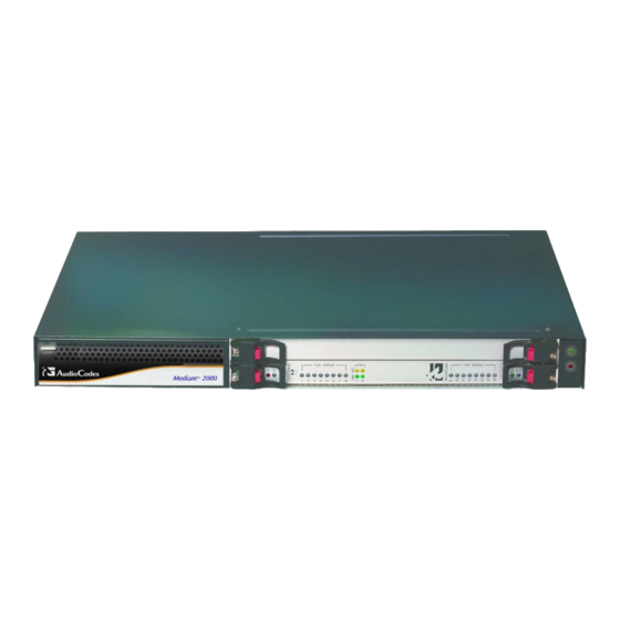
Installation Manual 2. Installing the Device Installing the Device This section describes the device's hardware installation. This includes a physical description of the device, unpacking the shipped package, and mounting and cabling procedures. Physical Description The device's chassis is an industrial platform that is 19” wide, 1U high rack-mount and 12” deep. -
Page 10: Rear Panel
Mediant 2000 Item # Label Component Description Reset button. Note: This button is currently reserved for future use. T1/E1 STATUS E1/T1 Trunk Status LEDs (for each of the 9-16 trunks). PWR and Blade slot status LEDs. SWAP READY Power and Fan LEDs. -
Page 11: Table 2-2: Rear Panel Component Descriptions
Installation Manual 2. Installing the Device Table 2-2: Rear Panel Component Descriptions Item # Label Component Description RTM locking screws (or RTM latches). Two 10/100Base-TX, RJ-45 shielded ports. This dual Ethernet interface provides an Ethernet redundancy scheme (active / standby), offering protection against Ethernet failure. TRUNKS (16 spans) The connector depends on the number of required spans: -or-... -
Page 12: Unpacking And Checking Package Contents
Mediant 2000 Unpacking and Checking Package Contents Follow the procedure below for unpacking and checking the received carton in which the device is shipped. To unpack the device and verify content: Open the carton and remove packing materials. Remove the device from the carton. -
Page 13: Mounting The Device
Installation Manual 2. Installing the Device Mounting the Device The device can be mounted in one of the following ways: Desktop mounting (refer to 'Desktop Mounting' on page 13). 19-inch rack mounting (refer to '19-inch Rack Mounting' on page 13). 2.3.1 Desktop Mounting The device can be mounted on a desktop by attaching the four anti-slide bumpers... -
Page 14: Figure 2-5: Front View With 19-Inch Rack-Mount Brackets
Mediant 2000 Warning: When mounting the chassis in a 19-inch rack by attaching it to the rack's frame holes, it is MANDATORY to use two additional rear-mounting brackets (not supplied). To install the device in a 19-inch rack by attaching it to the rack's frame... -
Page 15: Cabling The Device
Installation Manual 2. Installing the Device Cabling the Device This section describes the cabling of the device. Electrical Earthing The device must be permanently connected to the earth using the screw provided on the rear panel. Use 14-16 AWG wire and a proper ring terminal for the earthing. -
Page 16: Earthing (Grounding) The Device
Mediant 2000 Cabling for eight trunks and DC power: Figure 2-7: Rear-Panel Cabling for 8 Trunks (DC Power) 2.4.1 Earthing (Grounding) the Device The device must be permanently connected to earth (ground), using an equipment-earthing conductor. Protective Earthing The equipment is classified as Class I EN60950 and UL60950 and must be earthed at all times. -
Page 17: Figure 2-8: 50-Pin Female Telco Board-Mounted Connector
Installation Manual 2. Installing the Device The 50-pin male Telco cable connector must be wired according to the pinouts in the table below, and to mate with the female connector illustrated in the figure below. Figure 2-8: 50-pin Female Telco Board-Mounted Connector Table 2-3: E1/T1 Connector Pinouts for Each 50-pin Telco Connector E1/T1 Trunk Number Tx Pins (Tip/Ring) -
Page 18: Connecting The Ethernet Interface
Mediant 2000 2.4.3 Connecting the Ethernet Interface The device provides two 10/100Base-TX RJ-45 ports for connection to the Ethernet network. The dual ports provide Ethernet redundancy. To connect the Ethernet interface: Connect a standard Category 5 network cable to the Ethernet RJ-45 port (labeled ETH) on the device's rear panel. -
Page 19: Connecting The Power Supply
Installation Manual 2. Installing the Device 2.4.4 Connecting the Power Supply The connection to the power supply depends on the supported hardware configuration: Single or dual AC power (refer to 'Connecting the AC Power Supply' on page 19). DC power (refer to 'Connecting the DC Power Supply' on page 19). 2.4.4.1 Connecting the AC Power Supply The device can support up to two AC power interfaces (single or dual). -
Page 20: Figure 2-11: Dc Power Terminal Block Screw Connector
Mediant 2000 To connect power using a DC terminal block screw connector: Create a DC cable by inserting two 14-16 AWG insulated wires into the supplied terminal block adaptor (refer to the figure below), and then fasten the two screws, each one located directly above each wire. -
Page 21: Connecting The Rs-232 Port To A Pc
Installation Manual 2. Installing the Device 2.4.5 Connecting the RS-232 Port to a PC Follow the procedure below to connect the device's serial (RS-232) interface to a PC. Note: The RS-232 port is available only on the 1-, 2- and 4-span hardware configurations. -
Page 22: Inserting And Extracting Blades
Mediant 2000 Inserting and Extracting Blades The device's 1610 blade (form factor 6U PICMG 2.0 single slots) is hot-swappable and therefore, can be inserted and extracted from a slot while the chassis is under power. However, it is recommended that you power down the chassis and refer to the notes below before replacing the components. -
Page 23: Configuring The Device
Installation Manual 3. Configuring the Device Configuring the Device This section describes initial, basic setup configuration for the device, using the device's embedded Web server (Web interface). Note: The device is supplied with application software (cmp file) already residing on its flash memory. -
Page 24: Assigning An Ip Address Using Http
Mediant 2000 3.1.1 Assigning an IP Address using HTTP You can assign an IP address to the device, using the device's Web interface. To assign an IP address using HTTP: Disconnect the device from the network and reconnect it to a PC using one of the following methods: •... -
Page 25: Assigning An Ip Address Using Bootp
Installation Manual 3. Configuring the Device Change the device's IP address, by performing the following: Open the ‘Multiple Interface Table’ page, (Configuration tab > Network Settings menu > IP Settings). Define the device's IP address, subnet mask, and default Gateway IP address (for “OAMP + Media + Control”... -
Page 26: Figure 3-2: Bootp Client Configuration Screen
Mediant 2000 In the ‘Subnet’ field, enter the subnet mask (in dotted-decimal notation) that you want to assign to the device. Ensure that the subnet mask is valid, otherwise, the device may not function. In the ‘Gateway’ field, enter the IP address of the default gateway (if any). -
Page 27: Assigning An Ip Address Using The Cli
Installation Manual 3. Configuring the Device 3.1.3 Assigning an IP Address using the CLI You can assign an IP address to the device, using command-line interface (CLI). To assign an IP address via the CLI (if supported): Connect the device's RS-232 port to either COM1 or COM2 communication port on your PC (refer to Connecting the RS-232 Port to Your PC on page 20). -
Page 28: Configuring Basic Sip Parameters
Mediant 2000 Configuring Basic SIP Parameters Once you have completed the previous sections, you are ready to start configuring the device using the Web interface. For information on how to fully configure the device, refer to the device's User’s Manuals. -
Page 29: Enabling Channels And Configuring Call Routing (Example)
Installation Manual 3. Configuring the Device 3.2.1 Enabling Channels and Configuring Call Routing (Example) This section provides an example for enabling the device's channels and for configuring Tel (PSTN)-to-IP call routing. This includes assigning the channels a telephone number and then routing calls (e.g., of dialed numbers with prefix 10) from these channels to a specific IP destination (e.g., IP address 10.33.24.14). -
Page 30: Configuring Pstn Trunks
Mediant 2000 3.2.2 Configuring PSTN Trunks This section describes how to configure the configure the device's E1/T1 PRI trunks. To configure the trunks: Open the ‘Trunk Settings’ page (Configuration tab > PSTN Settings menu > Trunk Settings). Figure 3-5: Trunk Settings Page... - Page 31 Installation Manual 3. Configuring the Device From the ‘Clock Master’ drop-down list, select the trunk's clock source: • ‘Recovered’ = clock source is recovered from the trunk. • ‘Generated’ = clock source is provided by the internal TDM bus clock source (according to the parameter ‘TDM Bus Clock Source’).
-
Page 32: Saving And Resetting The Device
Mediant 2000 Saving and Resetting the Device To apply configuration changes to the device's volatile memory (RAM), click the Submit button located on the page in which you are configuring. Modifications to parameters with on-the-fly capabilities are immediately applied to the device; other parameters are applied only after a device reset. -
Page 33: Changing Login User Name And Password
Installation Manual 3. Configuring the Device Changing Login User Name and Password To prevent unauthorized access to the Web interface, two Web user accounts (login accounts) are available (primary and secondary) with assigned user name and password. For detailed information on the Web user accounts, refer to the device's User’s Manual. Tip: If you do not know your user name and password, you can use AudioCodes BootP/TFTP utility to access the device, by re-flash the load and resetting the... -
Page 34: Backing Up And Restoring Configuration
Mediant 2000 Backing Up and Restoring Configuration You can save a copy/backup of the device's current configuration settings as an ini file to a folder on your PC, using the 'Configuration File' page. The saved ini file includes only parameters that were modified and parameters with other than default values. The 'Configuration File' page also allows you to load an ini file to the device. -
Page 35: Upgrading The Device
Installation Manual 3. Configuring the Device Upgrading the Device You can upgrade the device with the following files, using the device's Web interface: Firmware (cmp) file using the Web interface's Software Update Wizard (refer to 'Software Upgrade Wizard' on page 35). Auxiliary and ini files using the 'Load Auxiliary Files' page (refer to 'Upgrading the ini and Auxiliary Files' on page 38). -
Page 36: Figure 3-8: Start Software Upgrade Wizard Screen
Mediant 2000 To use the Software Upgrade Wizard: Stop all traffic on the device (refer to the note above). Open the 'Software Upgrade Wizard' (Management tab > Software Update menu > Software Upgrade Wizard); the 'Software Upgrade Wizard' page appears. -
Page 37: Figure 3-10: End Process Wizard Page
Installation Manual 3. Configuring the Device Click the Browse button, navigate to the cmp file, and then click Send File; the cmp file is loaded to the device and you're notified as to a successful loading. Click one of the following buttons: •... -
Page 38: Loading Ini And Auxiliary Files
Mediant 2000 3.6.2 Loading ini and Auxiliary Files The auxiliary files (and ini file) are dat files that can be loaded to the device to provide enhanced device provisioning. For detailed information on these files, refer to the device's User's Manual. - Page 39 Installation Manual 3. Configuring the Device Click the Browse button corresponding to the file type that you want to load, navigate to the folder in which the file is located, and then click Open; the name and path of the file appear in the field next to the Browse button.
- Page 40 Mediant 2000 Reader’s Notes Installation Manual Document #: LTRT-70113...
-
Page 41: Monitoring The Device
Installation Manual 4. Monitoring the Device Monitoring the Device The operating status of the device can be monitored in the following ways: Monitoring the device's hardware front-panel LEDs (refer to 'Front-Panel LEDs' on page 41). Monitoring the device using the Web interface (refer to 'Web Interface' on page 42). Front-Panel LEDs The operating status LEDs on the front panel of the device are described in the tables below:... -
Page 42: Web Interface
Mediant 2000 Note: On the front panel, 16 LEDs are provided for 16-span units and 8 LEDs are provided for 1-span, 2-, 4-, and 8-span units. In the case of 1-, 2-, and 4-span units, the extra LEDs are not used. -
Page 43: Viewing Channel Status
Installation Manual 4. Monitoring the Device • Source: element from which the alarm was generated • Description: brief explanation of the alarm • Date: date and time that the alarm was generated 4.2.2 Viewing Channel Status The 'Home' page displays channel port icons that indicate the voice channels' operating status. - Page 44 Installation Manual Version 6.0 www.audiocodes.com...
Need help?
Do you have a question about the Mediant 2000 and is the answer not in the manual?
Questions and answers