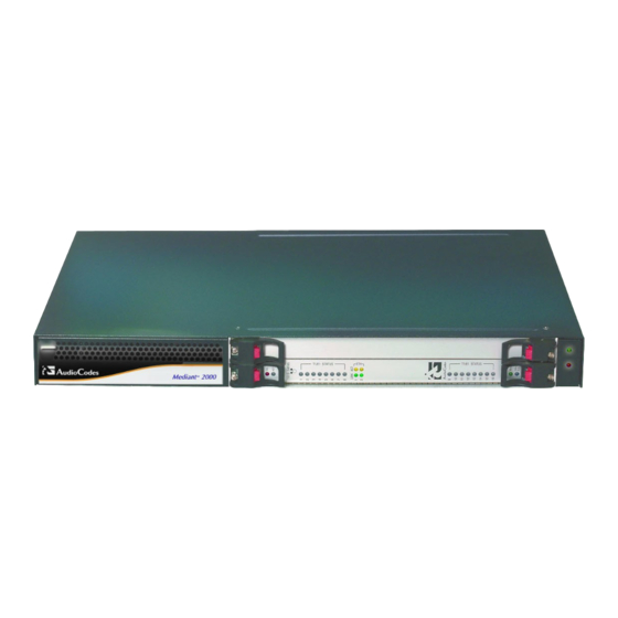
AudioCodes Mediant 2000 Installation Manual
Vop media gateway fast track mgcp, megaco, h.323 & sip
Hide thumbs
Also See for Mediant 2000:
- User manual (702 pages) ,
- Installation manual (44 pages) ,
- Hardware installation manual (30 pages)

Related Manuals for AudioCodes Mediant 2000


Summary of Contents for AudioCodes Mediant 2000
- Page 1 Mediant™ 2000 Fast Track Installation Guide MGCP, MEGACO, H.323 & SIP Version 4.4 Document #: LTRT-70102...
- Page 2 “Mediant 2000 SIP Release Notes”, Document #. LTRT-690xx Notice This Fast Track Installation Guide describes the installation of AudioCodes’ Mediant 2000 MGCP, MEGACO, H.323 or SIP media gateways. Information contained in this document is believed to be accurate and reliable at the time of printing. However, due to ongoing product improvements and revisions, AudioCodes cannot guarantee the accuracy of printed material after the Date Published nor can it accept responsibility for errors or omissions.
-
Page 3: Table Of Contents
3.3 Provisioning H.323 Parameters......................18 3.4 Provisioning SIP Parameters......................20 3.5 Trunk Configuration .......................... 22 Changing the Mediant 2000 Password....................23 Restoring and Backing Up the Mediant 2000 Configuration ..............24 Monitoring the Mediant 2000........................25 6.1 Monitoring the Mediant 2000 LEDs ....................25 6.1.1 Mediant 2000 chassis’... - Page 4 Figure 2-3: Mediant 2000 Front View with Side Brackets.................. 8 Figure 2-4: Mediant 2000 Rear Panel Cabling (16 Trunks, AC Power)............. 9 Figure 2-5: Mediant 2000 Rear Panel Cabling (8 Trunks, DC Power)) ............10 Figure 2-6: 50-pin Female Telco Board-Mounted Connector ................11 Figure 2-7: Pinout of RJ-48c Trunk Connectors ....................
-
Page 5: Quick Setup For The Mediant 2000
1. Quick Setup for the Mediant 2000 Quick Setup for the Mediant 2000 This guide provides information on how to install the Mediant 2000 for the first time. Prior knowledge of IP networks is required. Refer to the configuration procedures, outlined in... -
Page 6: Installing The Mediant 2000
Cable the Mediant 2000 (refer to Section on page 9). After powering-up the Mediant 2000, the Ready and LAN LEDs on the front panel turn to green (after a self-testing period of about 60 seconds). Any malfunction changes the Ready LED to red... -
Page 7: Package Contents
Four anti-slide bumpers for desktop installation. Figure 2-2: Plastic Bag Contents Mounting the Mediant 2000 AudioCodes’ Mediant 2000 can be mounted on a desktop, or installed in a standard 19-inch rack. Refer to Section on page for cabling the Mediant 2000. -
Page 8: Figure 2-3: Mediant 2000 Front View With Side Brackets
(of your choosing) in the vertical tracks of the 19-inch rack. Use standard 19-inch rack bolts (not provided) to fasten the device to the frame of the rack. AudioCodes recommends using two additional (not supplied) rear mounting brackets to provide added support. -
Page 9: Cabling The Mediant 2000
Cabling the Mediant 2000 The Mediant 2000 is available in all configuration combinations, i.e., AC or DC, in the 16-trunk, 8- trunk, 4-trunk, 2-trunk or 1-trunk device. The 16-trunk dual AC... -
Page 10: Connecting The E1/T1 Trunk Interfaces
12). 2.3.1 Connecting the E1/T1 Trunk Interfaces Connect the Mediant 2000 E1/T1 Trunk Interfaces using one of to following methods: If you are using Trunk cables with 50-pin Telco connectors (16-trunk device), take these 3 steps: Attach the Trunk cable with a 50-pin male Telco connector to the 50-pin female Telco connector labeled “Trunks 1 8”... -
Page 11: Installing The Ethernet Connection
= shield 2.3.2 Installing the Ethernet Connection When initializing (connecting the Mediant 2000 to the PC for the first time) use one of the following two methods: • Either use an Ethernet cross-over cable to directly connect the network card on your computer to one of the RJ-45 jacks on the Mediant 2000. -
Page 12: Connecting The Power Supply
• The dual AC connections provide load-sharing redundancy. 2.3.3.2 Connecting the DC Power Supply To connect the Mediant 2000 to a DC power supply use one of these two options: • DC Terminal block with a screw connection type. •... -
Page 13: Figure 2-9: Dc Power Connector With A Screw Connection Type Terminal Block
If you are using a terminal block with a crimp connection type take these 3 steps: Remove the DC adaptor (screw connection type) that is attached to the Mediant 2000 rear panel. Connect the two insulated wires to the correct DC power supply. Ensure that the connections... -
Page 14: Initializing The Mediant 2000
Open a standard Web-browsing application such as Microsoft™ Internet Explorer™ (Version 6.0 and higher) or Netscape™ Navigator™ (Version 7.0 and higher). In the URL field, specify the IP address of the first module of the Mediant 2000 (i.e., http://10.1.10.10); the Embedded Web Server’s ‘Enter Network Password’ screen appears,... -
Page 15: Figure 3-1: Embedded Web Server Login Screen
Repeat steps 1 to 11 for the Mediant 2000 second module (if used). You are now ready to start using the Mediant 2000 . For information on how to fully configure the VoIP gateway, refer to the Mediant 2000 User’s Manuals. -
Page 16: Provisioning Mgcp / Megaco Parameters
Setup’ screen is accessed, as shown in Figure 3-2. Figure 3-2: Mediant 2000 MGCP/MEGACO Quick Setup Screen To provision basic MGCP / MEGACO parameters take these 16 steps: In the ‘Default Gateway Address’ field, enter the IP address for the default gateway. If you do not know the IP address for the default gateway, contact your network administrator. - Page 17 PSTN or PBX side is configured as ‘Network side’, and vice-versa. If you don’t know the Mediant 2000 ISDN termination side, choose ‘User Side’ and refer to the ‘Status & Diagnostics>Channel Status’ screen. If the D-channel alarm is indicated, choose ‘Network Side’.
-
Page 18: Provisioning H.323 Parameters
Select the coder that best suits your VoIP system requirements. The default coder is: G.7231 30 msec. To program the entire list of coders you want the Mediant 2000 to use, click the button on the left side of the ‘1 Coder’... - Page 19 Click the SUBMIT button; the ‘Tel to IP Routing’ table is automatically updated. Click the Close Window button. For more information on the ‘Tel to IP Routing’ table refer to the H.323 Mediant 2000 User’s Manual. Enable E1/T1 B-channels by completing these steps: Click the arrow button next to the ‘Trunk Group Table’...
-
Page 20: Provisioning Sip Parameters
Enable the DMZ configuration on the residential router for the LAN port where the Mediant 2000 gateway is connected. Enter the public IP address for the Mediant 2000 in the ‘NAT IP Address’ field (in addition to the gateway’s local IP address). - Page 21 Select the coder that best suits your VoIP system requirements. The default coder is: G.7231 30 msec. To program the entire list of coders you want the Mediant 2000 to use, click the button on the left side of the ‘1 Coder’...
-
Page 22: Trunk Configuration
PSTN or PBX side is configured as ‘Network side’, and vice-versa. If you don’t know the Mediant 2000 ISDN termination side, choose ‘User Side’ and refer to the ‘Status & Diagnostics>Channel Status’ screen. If the D-channel alarm is indicated, choose ‘Network Side’. -
Page 23: Changing The Mediant 2000 Password
4. Changing the Mediant 2000 Password Changing the Mediant 2000 Password To prevent unauthorized access to the Mediant 2000 , it is recommended that you change the username and password that is used to access the Embedded Web Server. To change the username and password take these 7 steps: Access the Mediant 2000 Embedded Web Server via a standard Web browser. -
Page 24: Restoring And Backing Up The Mediant 2000 Configuration
Mediant 2000 Restoring and Backing Up the Mediant 2000 Configuration The ‘Configuration File’ screen enables you to restore (load a new ini file to the gateway) or to back up (make a copy of the VoIP gateway ini file and store it in a directory on your computer) the current configuration the gateway is using. -
Page 25: Monitoring The Mediant 2000
The Mediant 2000 provides several ways of monitoring the status of the gateway: • Monitoring the Mediant 2000 LEDs (refer to Section below). • Monitoring the Mediant 2000 trunks and B-channels via the Embedded Web Server (refer to Section on page 26). Monitoring the Mediant 2000 LEDs 6.1.1 Mediant 2000 chassis’... -
Page 26: Monitoring The Mediant 2000 Trunks And B-Channels
Blue The cPCI board was inserted successfully. During correct Mediant 2000 operation, the ACT LED is lit green, the FAIL LED is off. Changing of the FAIL LED to red indicates a failure. Monitoring the Mediant 2000 Trunks and B-channels To monitor the status of the trunks and B-channels: •... -
Page 27: Figure 6-3: Specific B-Channel Status Details
Fast Track Installation Guide 6. Monitoring the Mediant 2000 The color of each trunk (Figure 6-2) shows the status of that trunk. • Gray (Disable) indicates this trunk is either disabled or assigned a protocol type none. • Green (Active - OK) indicates this trunk is synchronized. -
Page 28: Upgrading The Mediant 2000
Mediant 2000 Upgrading the Mediant 2000 To upgrade the Mediant 2000 (load new software or auxiliary files onto the VoIP gateway) use the Software Update feature, available through the Embedded Web Server. The ‘Software Update’ menu comprises two submenus: •... -
Page 29: Figure 7-2: Load A Cmp File Screen
Fast Track Installation Guide 7. Upgrading the Mediant 2000 Note: At this point, the process can be canceled with no consequence to the device (click the Cancel button). If you continue the process (by clicking the Start Software Upgrade button, the process must be followed through and completed with a device reset at the end. -
Page 30: Figure 7-3: Cmp File Successfully Loaded Into The Device Notification
Mediant 2000 Figure 7-3: cmp File Successfully Loaded into the Device Notification Note that the four action buttons ( Cancel , Reset , Back , and Next ) are now activated (following cmp file loading). You can now choose to either: Click Reset ;... -
Page 31: Figure 7-4: Load An Ini File Screen
Fast Track Installation Guide 7. Upgrading the Mediant 2000 Figure 7-4: Load an ini File Screen In the ‘Load an ini File’ screen, you can now choose to either: Click Browse and navigate to the ini file; the check box ‘Use existing configuration’, by default checked, becomes unchecked. -
Page 32: Figure 7-5: Load A Cpt File Screen
Figure 7-5: Load a CPT File Screen Follow the same procedure you followed when loading the ini file (refer to Step 6). The same procedure applies to the ‘Load a VP file’ (not applicable to the Mediant 2000 gateway) screen and ‘Load a coefficient file’ screen. -
Page 33: Figure 7-6: Finish Screen
Fast Track Installation Guide 7. Upgrading the Mediant 2000 Figure 7-6: FINISH Screen Figure 7-7: ‘End Process’ Screen Click the End Process button; the ‘Quick Setup’ screen appears and the full Web application is reactivated. Version 4.4 August 2004... -
Page 34: Updating The Auxiliary Files
(software is loaded from the flash). Up to 8 different CAS files containing specific CAS protocol definitions. These files are provided by AudioCodes to support various types of CAS signaling. Voice Prompts The voice announcement file contains a set of Voice Prompts to be played by the Mediant 2000 during operation on Call Agent request. -
Page 35: Figure 7-8: Auxiliary Files Screen
Click the Reset button in the middle of the screen; the auxiliary files are saved into flash and the Mediant 2000 restarts. This takes approximately 60 seconds to complete. When the Mediant 2000 has finished restarting, the Ready and LAN LEDs on the front panel are lit green. -
Page 36: Regularity Information
4 HaHoresh Street, Yehud 56470, Israel. Type of Equipment: Digital VoIP System. Model Numbers: IPmedia 2000, Mediant 2000, Stretto 2000. I, the undersigned, hereby declare that the equipment specified above conforms to the above Directives and Standards. October, 2003 Yehud, Israel... - Page 37 If this happens the telephone company will provide advance notice in order for you to make necessary modifications to maintain uninterrupted service. Should you experience trouble with this telephone equipment, contact: AudioCodes Inc, San Jose, CA USA. Tel: 1 408 577 0488 Do not attempt to repair this equipment! Facility Interface Code: 04DU9.BN, 04DU9.DN, 04DU9.1KN, 4DU9.ISN...
- Page 38 Mediant 2000 USA Headquarters : AudioCodes Inc, 2890 Zanker Road, Suite # 200, San Jose, CA 95134. Tel: +1-408-577-0488 - Fax: +1-408-577-0492 International Headquarters : AudioCodes Ltd, 1 Hayarden Street, Airport City, Lod 70151, Israel. Tel: +972-3-976 4000 - Fax: +972-3-976 4040...
Need help?
Do you have a question about the Mediant 2000 and is the answer not in the manual?
Questions and answers