AudioCodes Mediant 2000 Installation Manual
Voip media gateway
Hide thumbs
Also See for Mediant 2000:
- User manual (702 pages) ,
- Installation manual (44 pages) ,
- Hardware installation manual (30 pages)

Subscribe to Our Youtube Channel
Related Manuals for AudioCodes Mediant 2000


Summary of Contents for AudioCodes Mediant 2000
- Page 1 Fast Track Installation Guide MGCP, MEGACO, H.323 & SIP Version 4.6 Document #: LTRT-70105...
- Page 3 Mediant 2000 Fast Track Installation Guide MGCP, MEGACO, H.323 & SIP Version 4.6 Document #: LTRT-70105 Published July 2005...
- Page 4 Notice This Fast Track Installation Guide describes the installation of AudioCodes’ Mediant 2000 MGCP, MEGACO, H.323 and SIP media gateways. Information contained in this document is believed to be accurate and reliable at the time of printing. However, due to ongoing product improvements and revisions, AudioCodes cannot guarantee the accuracy of printed material after the Date Published nor can it accept responsibility for errors or omissions.
-
Page 5: Table Of Contents
2.3 Mounting the Mediant 2000.........................9 2.3.1 Mounting the Mediant 2000 on a Desktop ................9 2.3.2 Installing the Mediant 2000 in a 19-inch Rack ..............9 2.4 Cabling the Mediant 2000 .........................10 2.4.1 Connecting the E1/T1 Trunk Interfaces ................12 2.4.2... - Page 6 List of Tables Table 2-1: Mediant 2000 Front View Component Descriptions................. 7 Table 2-2: Mediant 2000 Rear Panel Cabling (16 Trunks, Dual AC Power) Component Descriptions ..11 Table 2-3: Mediant 2000 Rear Panel Cabling (8 Trunks, DC Power) Component Descriptions..... 11 Table 2-4: E1/T1 Connections on each 50-pin Telco Connector ..............
-
Page 7: Customer Support
Mediant & TP Series SIP Digital Gateways User's Manual LTRT-690xx Mediant & TP Series SIP Digital Gateways Release Notes The Mediant 2000 is supplied as a sealed unit and must only be Warning: serviced by qualified service personnel. Where “network” appears in this manual, it means LAN, WAN, etc. accessed Note: via the gateway’s Ethernet interface. -
Page 8: Quick Start
Mediant 2000 Quick Start This Fast Track Installation Guide helps you to set up the Mediant 2000 for the first time. Prior knowledge of IP networks is preferred. Refer to Figure 1-1 for the quick setup flow. For detailed information on how to fully configure the gateway, refer to the Mediant 2000 User’s Manuals. -
Page 9: Installing The Mediant 2000
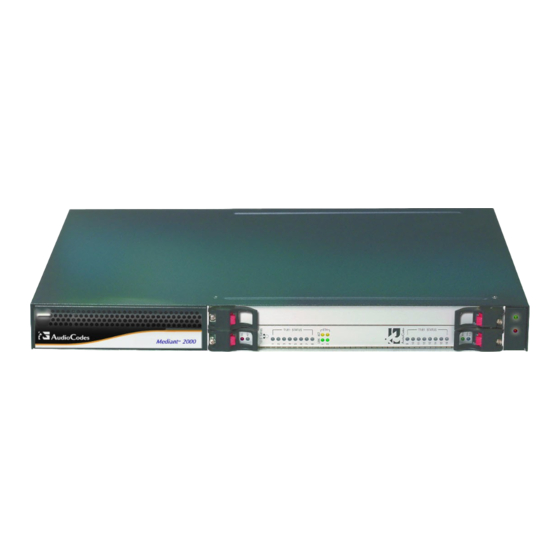
2. Installing the Mediant 2000 Installing the Mediant 2000 Figure 2-1 shows the front view of the Mediant 2000 media gateway. For information on the Mediant 2000 LEDs refer to Section on page 32. Figure 2-1: Mediant 2000 Front View... -
Page 10: Unpacking
Cable the Mediant 2000 (refer to Section on page 10). After powering-up the Mediant 2000, the Ready and LAN LEDs on the front panel turn to green (after a self-testing period of about 3 minutes). Any malfunction changes the Ready LED to red... -
Page 11: Mounting The Mediant 2000
2. Installing the Mediant 2000 Figure 2-2: 19-inch Rack & Desktop Accessories Mounting the Mediant 2000 The Mediant 2000 can be mounted on a desktop, or installed in a standard 19-inch rack. Refer to Section on page for cabling the Mediant 2000. -
Page 12: Cabling The Mediant 2000
Cabling the Mediant 2000 The Mediant 2000 is available in many configurations, i.e., AC or DC, in the 16-trunk, 8-trunk, 4- trunk, 2-trunk or 1-trunk device. The 16-trunk dual AC (Figure... -
Page 13: Figure 2-4: Mediant 2000 Rear Panel Cabling (16 Trunks, Dual Ac Power)
Fast Track Installation Guide 2. Installing the Mediant 2000 Figure 2-4: Mediant 2000 Rear Panel Cabling (16 Trunks, Dual AC Power) Table 2-2: Mediant 2000 Rear Panel Cabling (16 Trunks, Dual AC Power) Component Descriptions Item # Label Component Description RTM locking screws. -
Page 14: Connecting The E1/T1 Trunk Interfaces
2.4.1 Connecting the E1/T1 Trunk Interfaces Connect the Mediant 2000 E1/T1 Trunk Interfaces using either Telco or RJ-48 connectors: With 50-pin Telco connectors (16-trunk device), take these 3 steps: Attach the Trunk cable with a 50-pin male Telco connector to the 50-pin female Telco connector labeled “Trunks 1 8”... -
Page 15: Installing The Ethernet Connection
3 = Rx+ 6 = Rx- 2.4.3 Connecting the Power Supply Connect the Mediant 2000 to the power supply using one of the following methods: 2.4.3.1 Connecting the AC Power Supply When using a single AC power cable: Attach one end of the supplied 100/240 VAC power cable to the rear AC socket and connect the other end to the correct earthed AC power supply. -
Page 16: Connecting The Dc Power Supply
Each of the dual power cables can be connected to different power phases. 2.4.3.2 Connecting the DC Power Supply To connect the Mediant 2000 to a DC power supply use one of these two options: • DC Terminal block with a screw connection type. -
Page 17: Figure 2-10: Dc Terminal Block Crimp Connector
2. Installing the Mediant 2000 When using a DC terminal block crimp connector, take these 3 steps: Remove the DC adaptor (screw connection type) that is attached to the Mediant 2000 rear panel. Connect the two insulated wires to the correct DC power supply. Ensure that the connections... -
Page 18: Configuring The Mediant 2000
MAC and IP addresses (Table 3-1 shows the default IP addresses of the Mediant 2000). To assign an IP address to each of the Mediant 2000 modules use one of the following methods: •... -
Page 19: Assigning An Ip Address Using Bootp
If your network doesn’t feature a default gateway, enter a dummy value in the ‘Default Gateway IP Address’ field. Click the Reset button and click OK in the prompt; the Mediant 2000 applies the changes and restarts. This takes approximately 3 minutes to complete. When the Mediant 2000 has finished restarting, the Ready and LAN LEDs on the front panel are lit green. -
Page 20: Assigning An Ip Address Using The Cli
Click Apply to save this entry to the list of clients. Click OK; the ‘Client Configuration’ screen is closed. Use the reset button (located on the Mediant 2000 front panel) to physically reset the gateway causing it to use BootP; the Mediant 2000 changes its network parameters to the values provided by the BootP. -
Page 21: Restoring Networking Parameters To Their Initial State
To save the configuration, at the prompt, type ‘SAR’ and press enter; the Mediant 2000 restarts with the new network settings. Restoring Networking Parameters to their Initial State You can use the ‘Reset’ button to restore the Mediant 2000 networking parameters to their factory default values (described in Table 3-1) and to reset the username and password. -
Page 22: Configuring The Mediant 2000 Basic Control Protocol Parameters
When you have completed the above relevant section you are then ready to start using the Mediant 2000. For information on how to fully configure the VoIP gateway, refer to the Mediant 2000 User’s Manuals. Once the gateway is configured correctly back up your settings by making a... -
Page 23: Configuring Basic Mgcp / Megaco Parameters
TDM bus clock source, according to the parameter ‘TDM Bus Clock Source’). For detailed information on the parameter ‘TDM Bus Clock Source’, refer to the Mediant 2000 MGCP/MEGACO User’s Manual. In the ‘Line Code’ field, select the Line Code. Use ‘B8ZS’ (bipolar 8-zero substitution) or ‘AMI’... - Page 24 In the ‘Trunk Name’ and ‘Endpoint Prefix’ fields, enter intuitive prefixes. Ensure that the definitions you choose are the definitions that the Call Agent is configured with to identify your Mediant 2000. In the ‘Trunk ID Offset’ field, you can enter a value to offset the numbers that represent the gateway’s trunks.
-
Page 25: Configuring Basic H.323 Parameters
Select the coder (i.e., vocoder) that best suits your VoIP system requirements. The default coder is: G.7231 30 msec. To program the entire list of coders you want the Mediant 2000 to use, click the button on the left side of the ‘1 Coder’... - Page 26 Click the Submit button; the ‘Tel to IP Routing’ table is automatically updated. Click Quick Setup; you’re returned to the ‘Quick Setup’ screen. For more information on the ‘Tel to IP Routing’ table refer to the H.323 Mediant 2000 User’s Manual.
-
Page 27: Configuring Basic Sip Parameters
Figure 3-5: Mediant 2000/SIP Quick Setup To configure basic SIP parameters, take these 10 steps: If the Mediant 2000 is connected to a router with NAT enabled, perform the following procedure. If it isn’t, leave the ‘NAT IP Address’ field undefined. - Page 28 Select the coder (i.e., vocoder) that best suits your VoIP system requirements. The default coder is: G.7231 30 msec. To program the entire list of coders you want the Mediant 2000 to use, click the button on the left side of the ‘1 Coder’...
-
Page 29: Configuring The Trunk Settings
Fast Track Installation Guide 3. Configuring the Mediant 2000 The following Sections from here, up to the end of this Fast Track Guide, Note: apply equally to MGCP, MEGACO, H.323 and SIP. Configuring the Trunk Settings To configure the trunk settings, take these 13 steps: Access the Embedded Web Server (refer to Section on page 19). - Page 30 PSTN or PBX side is configured as ‘Network side’, and vice-versa. If you don’t know the Mediant 2000 ISDN termination side, choose ‘User Side’ and refer to the ‘Status & Diagnostics>Channel Status’ screen. If the D-channel alarm is indicated, choose ‘Network Side’.
- Page 31 Click the Save Configuration button in the middle of the screen; a confirmation message appears when the save is complete. For more detailed information on configuring the Mediant 2000 trunk settings, refer to the Mediant 2000 User’s Manual. Version 4.6...
-
Page 32: Changing The Mediant 2000 Username And Password
Mediant 2000 Changing the Mediant 2000 Username and Password To prevent unauthorized access to the Embedded Web Server, two levels of security are available: Administrator and Monitoring. Each employs a different username and password. Users can access the Embedded Web Server as either: •... -
Page 33: Restoring And Backing Up The Mediant 2000 Configuration
Fast Track Installation Guide 5. Restoring and Backing Up the Mediant 2000 Configuration Restoring and Backing Up the Mediant 2000 Configuration The ‘Configuration File’ screen enables you to restore (load a new ini file to the gateway) or to back up (make a copy of the VoIP gateway ini file and store it in a directory on your PC) the current configuration the gateway is using. -
Page 34: Monitoring The Mediant 2000
The Mediant 2000 provides several ways of monitoring the status of the gateway: • Monitoring the Mediant 2000 LEDs (refer to Section below). • Monitoring the Mediant 2000 trunks and B-channels via the Embedded Web Server (refer to Section on page 33). Monitoring the Mediant 2000 LEDs 6.1.1 Mediant 2000 Chassis’... -
Page 35: Monitoring The Mediant 2000 Trunks And B-Channels
Blue The cPCI board was inserted successfully. During correct Mediant 2000 operation, the ACT LED is lit green, the FAIL LED is off. Changing of the FAIL LED to red indicates a failure. Monitoring the Mediant 2000 Trunks and B-channels To monitor the status of the trunks and B-channels: •... -
Page 36: Upgrading The Mediant 2000
Mediant 2000 Upgrading the Mediant 2000 The ‘Software Update’ menu enables users to upgrade the Mediant 2000 software by loading a new cmp file along with the ini and a suite of auxiliary files, or to update the existing auxiliary files. -
Page 37: Figure 7-2: Load A Cmp File Screen
Figure 7-2: Load a cmp File Screen Click the Browse button, navigate to the cmp file and click the button Send File; the cmp file is loaded to the Mediant 2000 and you’re notified as to a successful loading (refer to Figure 7-3). -
Page 38: Figure 7-4: Load An Ini File Screen
Note that these are NOT the files you loaded in the previous Wizard steps. Click Reset; the Mediant 2000 resets, utilizing the new cmp and ini file you loaded up to now as well as utilizing the other configuration files. -
Page 39: Figure 7-6: Finish Screen
7. Upgrading the Mediant 2000 Button Result The Mediant 2000 ‘burns’ the newly loaded files to flash memory. The ‘Burning files to Reset flash memory’ screen appears. Wait for the ‘burn’ to finish. When it finishes, the ‘End Process’ screen appears displaying the burned configuration files (refer to Figure 7-7). -
Page 40: Updating The Auxiliary Files
Table 7-1: ini and Auxiliary Files Descriptions File Type Description Load the file to provision the Mediant 2000 parameters. The Embedded Web Server enables practically full device provisioning but customers may occasionally require new feature configuration parameters in which case this file is loaded. -
Page 41: Figure 7-8: Auxiliary Files Screen
Click the Reset button in the middle of the screen; the auxiliary files are saved into flash and the Mediant 2000 restarts. This takes approximately 3 minutes to complete. When the Mediant 2000 has finished restarting, the Ready and LAN LEDs on the front panel are lit green. -
Page 42: Regulatory Information
Undertegnede [AudioCodes Ltd] erklærer herved, at følgende udstyr [2000 Series] overholder de væsentlige krav og øvrige relevante krav i direktiv 1999/5/EF Dutch Hierbij verklaart [AudioCodes Ltd] dat het toestel [2000 Series] in overeenstemming is met de essentiële eisen en de andere relevante bepalingen van richtlijn 1999/5/EG English Hereby, [AudioCodes Ltd], declares that this [2000 Series] is in compliance with the essential requirements and other relevant provisions of Directive 1999/5/EC. -
Page 43: Industry Canada Notice
Should you experience trouble with this telephone equipment, contact: AudioCodes Inc, San Jose, CA USA. Tel: 1 408 577 0488. Do not attempt to repair this equipment! Do not attempt to repair this equipment! Facility Interface Code: 04DU9.BN, 04DU9.DN, 04DU9.1KN, 4DU9.ISN... - Page 44 www.audiocodes.com...
Need help?
Do you have a question about the Mediant 2000 and is the answer not in the manual?
Questions and answers