Table of Contents
Advertisement
Quick Links
Advertisement
Table of Contents

Subscribe to Our Youtube Channel
Related Manuals for Hilberling PT-8000A

Summary of Contents for Hilberling PT-8000A
- Page 1 HF / VHF Transceiver PT-8000A Operating Manual Version 2.00.33...
- Page 2 Copyright-notice to the ring binder title All Figure rights reserved by: Bundeswehr / PIZ Marine, DGzRS and Hilberling GmbH...
- Page 3 EU Hilberling GmbH Kieler Strasse 53 24768 Rendsburg Germany Logo and name of Hilberling GmbH are registered trademarks Distribution of the complete Document is desired However, each partial copy or distribution is prohibited Errors and changes excepted...
- Page 4 Keep in mind the performance limits or operating ranges of electrical connectors and interfaces. Set the PT-8000A RF-output level to less than the linear amplifier’s maximum input level to prevent amplifier damage.
-
Page 5: Table Of Contents
5.2 Connectors at Rear Panel / Connection Sockets J1 up to J4 ................. 8 5.3 Operating and Display Elements at Front Panel ..................9 Accessories 6.1 Microphone Hilberling T9 ......................... 9 6.2 Wiring / Cables ............................9 6.3 Operating Manual and Software/Documention CD ..................10 Installation / Initial Operation 7.1 Introduction ............................ - Page 6 11.3 Channel Operation 11.3.1 Recall of Stored Frequencies CHANNEL ..................34 11.3.2 Storage of Frequencies MEM ....................36 active in the Background 11.4 VFO Main Tuning Knob ( RX) and SUB VFO Tuning Knob (RX ) ......38 11.5 STEP VFO Control ..........................39 11.6 VFO Mangement ..........................
- Page 7 A2.3 Requirements and Procedure ......................A2.4 Setup Software and Firmware ......................A2.5 Install Update Program on PC ......................A2.6 Connect PT-8000A to PC by USB Data Cable ..................A2.7 Start and set up the Update Program ....................A2.7.1 Manual COM Port Setting ......................
- Page 8 OMMISSION TATEMENT The Hilberling PT-8000A was tested and found to be in compliance with 47 CFR, Part 15 of the FCC Rules, as an unintentional radiator and as a generic receiver. These limits are designed to provide reasonable protection against harmful interference in a residential installation.
-
Page 9: Introductory Notes
(contacting your carrier). We recommend to retain all packing material – it might be used for shipment of the radio. Listed below are the hardware and all accessories delivered with your PT-8000A. Make sure you have received and unpacked everything:... -
Page 10: Notes On Locating
(TVI/BCI). For your convenience you might raise the front of PT-8000A and HN-8000 by unfolding and locking tilt bails mounted at the front equipment feet into front position as shown on Fig. 1 (see next page). -
Page 11: Antenna Considerations / Antenna Tuner
– i.e. the SWR is close to 1.0. Therefore the PT-8000A is equipped with an automatic antenna tuner (ATU) which does not actually tune the antenna. The ATU instead matches the feed line to the final amplifiers so they always “see” a SWR close to 1.0. -
Page 12: Connectors Pt-8000A
PT-8000A ONNECTORS In this chapter the connectors at the front and rear panel of the PT-8000 are explained. Connectors at Rear Panel 4.1.1 HF/VHF Connectors J1 - J11 Fig. 2 Name Type Description VHF-ANT Input / Output VHF Antenna Range 110 ... 143,990 MHz (RX only) -
Page 13: Connection Sockets J12 - J22 And Operating Elements
Threaded Pin M6 Grounding stud – must be connected to station ground 10 MHz Ref. Input for an external 10 MHz reference signal (clock) for synchronization of PT-8000A to other equipment. The signal delivers +1dBm ±3dB level 10 MHz Ref. -
Page 14: Wiring Of J15 - J21
4.1.3 Wiring of J15 - J21 Name Type Function And Outline ext. SPKR Connector for add. 1 Tip 60 kHz OUT MAIN RX Panorama Display / 2 Ring 60 kHz OUT SUB RX Waterfall Diagram 3 Sleeve Caution: Using mono type plugs will shorten the audio output and may damage the transceiver ext. -
Page 15: Connectors At Front Panel
4.2.1 Connection Sockets 1 - 3 Fig. 4 Name Type Description MIC-PTT Microphone Threaded Socket Microphone connector for Hilberling T9 and Data input 0 dBm 8-pol PHONE EIA-453 / IEC 60603-11 Headphones (impedance 8 ... 600 Ohm) TRS 6.3 mm Socket CW-KEY EIA-453 / IEC 60603-11 Connector: –Keyer for CW (morse key/ keyer with Paddle / automatic keyer) -
Page 16: General Description
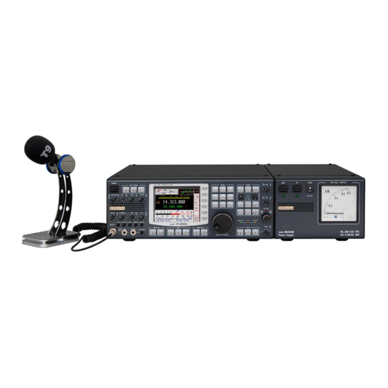
General Description Each PT-8000A is equipped with its power supply HN-8000, which delivers 13.8 V DC @ 8 Amps internal / 5 Amps. external and additional 50 V DC @ 14 Amp. max., i.e. the overall performance is about 900 Operating voltages from the mains can be in the range of 90 VAC to 260 VAC without any degradation in output power. -
Page 17: Operating And Display Elements At Front Panel
(LINE and PA). CCESSORIES Base Station Microphone Dynamic T9 Best suited for all voice operations is the Hilberling Dynamic T9 especially designed for the PT-8000A. Isolated from any mechanical vibrations and designed to be used from more closer as well as from greater distance it will always guarantee high fidelity audio and if desired an extra punch to the signal. -
Page 18: Operating Manual And Software/Documention Cd
Ground cable (HN-8000 ⬄ PT-8000A) length approx. 1.0 m Fig. 10 Speaker cable (HN-8000 ⬄ PT-8000A) length approx. 0.9 m Fig. 11 Data cable (PT-8000A / USB-B ⬄ PC / USB-A) length approx. 1.8 m Fig. 12 Operating Manual and Software/Documention CD This manual version 2.00.xx Fig. -
Page 19: Installation / Initial Operation
NSTALLATION NITIAL PERATION Introduction Prior to any operation of the PT-8000A read this Operation Manual carefully notably before activating the transmitter. The PT-8000A will be delivered with the following presettings: The preselectors of both RX are aligned and all data are stored in RX- CPU memory which is buffered through a NiCd battery. -
Page 20: Main Operating And Display Elements
Set internal Reference REF-SET When operating the PT-8000A with its internal reference (10MHz-VCXO) this control will allow calibration the VCXO. Tuning range ± 1 ppm (s. P. 54). The LED EXT-REF will illuminate if an external reference signal is detected... -
Page 21: Tft-Display
PT-8000A Operating Manual v2.00.33 TFT-Display The display of the PT-8000A shows relevant data of MAIN- and SUB-RX and the TX: All settings for the active RX Main settings for the RX in the background General Data for RX and TX ... - Page 22 More indications on the Display Fig. 16 Module/Function Description Options Page Voice Operated TX ON / OFF 3-Band TX-EQ Display Only if EQ menu is active Status-Field Antenna and RX adjustments s. Tab. 10 s. b. Temperature MAIN-CPU — LEVELER TX Audio Dynamic Controller ON / OFF PROCESSOR...
-
Page 23: Clustered Front Panel Controls
PT-8000A Operating Manual v2.00.33 Clustered Front Panel Controls Various fix function keys (pushbuttons; in opposite to softkeys with variable functions, right of display, see Page 13) are clustered in several button areas as shown below. Detailed description starts at Page 20. -
Page 24: Controls With Integrated Push-Button Function And Controls For Adjustments
ANTI TRIP DELAY Adjust Automatic Key Speed CW Adjustments / Settings for VOX Operation MAIN-RX Adjust Audio Volume MAIN-RX Deactivate Speaker PT-8000A (ON⬄OFF) SUB-RX Adjust Audio Volume SUB-RX Deactivate Speaker HN-8000 (ON⬄OFF) Fig. -
Page 25: Side Panel Controls (Level Adjustments)
Side Panel Controls (Level Adjustments) Sometimes it can be necessary to customize the input and output level of the PT-8000A for special requirements. Boreholes in both left and right hand side enable the access to trim potentiometers which allow manipulating the preadjustment of levels. -
Page 26: Pushbuttons With Led Status Display
Pushbuttons with LED Status Display To inform about the status of several main functions of the PT-8000A – in addition to display information – some pushbuttons are equipped with LED, respectively the status of fundamental operating conditions are indicated by LED. -
Page 27: Led Status Display
PT-8000A Operating Manual v2.00.33 LED Status Display The three main modes of PT-8000A (MAIN-RX / SUB-RX / TX) are displayed with colored LED. The PT-8000A incorporates a transmitter and two independent receivers MAIN-RX (MAIN RX and SUB-RX). Both receivers are permanently operating. Even if a SUB-RX receiver is in the background i.e. -
Page 28: Main- And Sub-Rx Operations
Fig. 23 The push button MAIN/SUB (located in the cluster MODE) toggles between the two RX changing their status active or background. After power on the PT-8000A the MAIN-RX is the active one (corresponding SUB-RX is working in the background). ... - Page 29 Receiving with SUB-RX on a separate antenna is limited however: Excessive field strength may trip the protection circuits. Receiving at frequencies adjacent to the transmitting frequency may be limited even by the superior dynamic characteristics of the PT-8000A receivers - which are of course finite.
-
Page 30: Modes Of Operation Mode
MODE ODES OF PERATION In order to select different operating modes pushbuttons (keys) are available in the clustered area MODE: Mode Page SSB / CW USB / LSB and CW / CW– s. b. AM / FM AM / AME USB / AME LSB and FM / FM RPT / FM RPT– DATA shiftable „submode“... -
Page 31: Cw Continuous Wave
PT-8000A Operating Manual v2.00.33 10.1.2 CW Continuous Wave In CW (resp. CW–) mode the parameters Pitch, Width und BFO as well as their specific value can be selected by using the knob WIDTH/SHIFT. Pushing WIDTH/SHIFT knob will cycle between the parameters: ... -
Page 32: Am / Fm Amplitude Modulation / Frequency Modulation
10.2 AM / FM Amplitude Modulation / Frequency Modulation Pushing AM/FM button activates the last used mode (AM, AME USB, AME LSB, FM, FM RPT or FM RPT+) and will call up the allocated softkey menu (AM menu respectively FM menu). Is this e.g. one of the AM modes, pushing AM/FM again toggles to the last activated FM mode. -
Page 33: Repeater Mode - How To Set The Repeater Frequency Shift
PT-8000A Operating Manual v2.00.33 10.2.1 Repeater Mode – How to Set the Repeater Frequency Shift When pushing SET RPT softkey (FM menu): SET RPT softkey will flash inverse. VFO display will show the actual transmit frequency. Band- respectively linear scale changes (range 0 ... 2.000) ... -
Page 34: Data Transmission (Digital Operation Modes)
10.3 DATA Transmission (Digital Operation Modes) The function DATA enables to send out signals which modulate the transmitter by using following inputs: 0 dBm IN (microphone socket MIC-PTT pin 4, see Page 7 Tab. 6) AUDIO DATA IN (J20 AUDIO IN/OUT pin 2, see Page 6 Tab. 4) This is basically possible with all modes –... -
Page 35: Selecting Frequencies
STEP-VFO knob. In case the BAND limits are exceeded trough tuning the last valid frequency that has been stored will remain. Press button again for return the PT-8000A to the last used frequency. The two stored frequencies of a band are correlated to each VFO. Selecting the alternate VFO will give access to another two frequencies in that band (which were used with this VFO). -
Page 36: Vhf Amateur Radio Bands
The following MF/HF amateur radio bands – slightly modified depending on IARU region the TRX will operate – are defined in the PT-8000A software as TX bands. They are directly selectable with band pushbuttons (except 60 m): Button Band Sign... - Page 37 PT-8000A Operating Manual v2.00.33 VHF menu Select 2 m band; the softkey will be displayed inverse (as shown here); pressing this key again will toggle between the last two frequencies used within this band. Select RX Range 110 ... 143.990 MHz; the softkey will be displayed inverse;...
-
Page 38: Transverter Operation
11.1.3 Transverter Operation Pushing Trans softkey (VHF menu) will call up allocated Transverter Select menu. If a transverter is already selected the softkey is displayed inverse. Transverter Select menu Return to VHF menu (see previous Page). Select transverter #1; the softkey will be displayed inverse; pushing again will call up the Transverter Band Select menu (see below). - Page 39 75.976 75.978 GHz Tab. 15 When the PT-8000A operates in transverter mode the transmitter output is directed to the TX-ext. connector on the rear panel (see Page 5 / Table 3 / socket J14). A transverter for one of the bands shown in Table 15 must be selected so that it can operate properly with drive power 10 m, 6 m or 2 m.
-
Page 40: Numerical Frequency Input Enter
11.2 Numerical Frequency Input ENTER Pushing ENTER button located in the cluster MODE will call up the ENTER menu and will activate the numerical frequency input: The frequency display will show blanks for all digits. A cursor indicates („_“) which digit can be edited. Fig. - Page 41 The last used softkey menu will be called up. If the entered frequency is outside of RX frequency ranges of the PT-8000A the VFO will jump to the upper border of the next lower RX frequency range. If input frequency is <...
-
Page 42: Channel Operation
Recalling of VFO adjustments (frequency, mode and filter bandwidth) is done pushing the CHANNEL button located in the cluster MODE. It gives access to 3 banks of memory each storing 99 channels provided by PT-8000A. When a memory channel is selected the stored adjustments are active with the current RX immediately. - Page 43 PT-8000A Operating Manual v2.00.33 Displayed Memory Channel Information CHANNEL Operation Fig. 42 Bank # Channel # Mode Bandwidth Stored Frequency SCAN Marker After selecting the memory bank through pushing softkeys BANK 1, BANK 2 and BANK 3 the control MEM/CH / STEP-VFO gives access to 99 memory channels by turning.
-
Page 44: Storage Of Frequencies Mem
11.3.2 Storage of Frequencies MEM Pushing MEM button located in the cluster MODE will store the frequency and additional VFO values of the active RX to one of the 297 memory channels organized in three banks with 99 memory channels each bank. Other than CHANNEL operation (see Page 34) the RX will stay on its current VFO adjustments while MEM functions are executed. - Page 45 PT-8000A Operating Manual v2.00.33 Mode and filter bandwidth are stored as well. When MEM function will be activated at first always the last used bank # is selected and displayed with its first (lowest number) empty memory. In case all memory channels are written the last used memory channel will be displayed and when pushing VFO⇨MEM overwritten.
-
Page 46: Vfo Main Tuning Knob ( Active Rx) And Sub Vfo Tuning Knob (Rx In The Background )
General frequency coverage of both RX is 9 kHz to 30 MHz, 50 to 54 MHz, 69.9 MHz to 70.7 MHz and 110 MHz to 148 MHz. Due to the frequency scheme of the PT-8000A the ranges between them are blanked out. Transmit operation is only possible on the allocated amateur radio bands of that IARU region in which one the TRX will operate after delivery (see Page 28 / Table 13 and 14). -
Page 47: Step Vfo Control
Neither pushing the knob nor turning the control for more than 3 seconds will terminate the STEP-VFO function. If re-activated by pushing the knob the cursor will appear at the last used position. When power up the PT-8000A and STEP-VFO will be activated the curser will initially occur at the 100 kHz position. -
Page 48: Vfo Mangement
11.6 VFO Management Both receivers (MAIN- and SUB-RX) have its own two VFOs – VFO A and VFO B. Switching between VFO A and VFO B is established through VFO A/B pushbutton. The button is located in the cluster VFO. In addition to frequencies the VFOs store filter bandwidth and operation mode. - Page 49 PT-8000A Operating Manual v2.00.33 In case the MAIN-RX is the active RX and its VFO A is the selected VFO, the Example VFO menu is displayed as follows: VFO menu active RX: MAIN-RX with selected VFO A The frequency of the selected VFO (shown: A) from the active RX (shown: MAIN-RX) will be copied to the selected VFO (without identifier) from the RX in the background (shown: SUB-RX).
-
Page 50: Split Operation
11.7 SPLIT Operation The VFO SPLIT operation in the PT-8000A is realized by using the MAIN and the SUB-RX. The selected VFO from the MAIN-RX determines the RX frequency, the selected VFO from the SUB-RX determines the TX frequency. To enable the VFO SPLIT operation, the MAIN-RX must be the active RX and the SUB-RX operates in the background. -
Page 51: Rit / Xit Operation
PT-8000A Operating Manual v2.00.33 11.8 RIT / XIT Operation RIT (Receiver Incremental Tuning) allows to shift/adjust the receiving frequency plus/minus 9.999 kHz against the transmit frequency. The MAIN-RX and the transmitter are no longer „transceive“. RIT is only possible with the MAIN-RX. -
Page 52: Locking Vfo Settings Lock
The tuning range of RIT/XIT amounts to ±9.999 kHz. The tuning increments of the CLAR control is identical to the selected STEP rate for frequency tuning of selected VFO. RIT/XIT are not available for SUB-RX. In case the SUB-RX is the active one (pushbutton MAIN/SUB) RIT/XIT and the offset are no longer displayed for the MAIN-RX which now operates in background. -
Page 53: Filter Bandwidth And Shift Function Filter Width / Shift
H I FT U NCT I O N Filtering in the PT-8000A is obtained in the 1st IF @ 40.7 MHz with a 6-pol. Filter and in the 2nd IF (IF-2) @ 10.7 MHz with an "IM Protector" said prefilter with bandwidth 0.5 kHz, 3 kHz and 15 kHz. -
Page 54: Filter Bandwidth Dsp Off
12.1 Filter Bandwidth DSP Off Depending on MODE the following Xtal-filters (analogue filters) and passband shifts are available (using WIDTH and SHIFT control) when DSP is not activated: Width 1.8 / 2.0 / 2.4 / 2.7 / 3.1 / 6.0 kHz LSB/USB Shift -200 Hz ... -
Page 55: Notch Filter: If-Notch And Dsp Multi Notch
L AN KE R 13.1 Notch Filter: IF-Notch and DSP Multi Notch Two notch filters of different type are available in the PT-8000A. One is working at 1 IF @ 40.7 MHz – it´s the classical type of manual notch filtering using a Xtal bridge –... -
Page 56: Dsp Noise Reduction Nr
13.2 DSP Noise Reduction NR Pushing the NR button located in the cluster DSP will active the Automatic Noise Reduction (ANR or NR): Fig. 65 Fig. 64 On the display the DSP NR is outlined as NR. DSP NR-LED will be on. NR is off after power on. -
Page 57: Squelch Sql
PT-8000A Operating Manual v2.00.33 QU E L C H The SQUELCH (SQ) is activated by default and will be affected by the control SQL which is located as depicted. The threshold for squelch operation is adjusted by turning the knob. -
Page 58: Rx Gain Control Agc / Rf-Gain
RX G AGC / RF-G AIN AI N O NT R O L 15.1 Automatic Gain Control AGC The AGC (Automatic Gain Control) is active after power on. Its hang time is 1 second (factory default value). Manual control of the AGC system is initiated through the AGC pushbutton. -
Page 59: Manual Gain Control Rf-Gain
PT-8000A Operating Manual v2.00.33 15.2 Manual Gain Control RF-GAIN The control knob RF (Manual Gain Control RF-GAIN) is located as depicted. It allows to cut off AGC action by pushing (AGC off) and to adjust an RF threshold by turning. -
Page 60: Storage Frequency Scanning Scan Temporary Disabled
SCAN T OR AG E R E Q U E N C Y C AN NI N G U N C T I O N E M P O R AR Y D I S AB L E D Pushing the SCAN button located in cluster FUNCTION will activate scanning of channels which are earmarked for scanning (CHANNEL - see Page 34). -
Page 61: Speaker / Calibration / Display / Voice Recorder Menu
Audio Norm will feed audio from MAIN-RX and SUB-RX to both speakers (PT- 8000A and HN-8000). Audio Split will separate audio from MAIN-RX and SUB-RX hence the MAIN- RX signal will be fed to PT-8000A speaker and the SUB-RX signal to HN-8000 speaker. True for both settings of speaker allocation: ... -
Page 62: Calibration Of Internal Reference Reference Calibration
17.2 Calibration of Internal Reference Pushing CAL softkey (MENU menu) will call up the Calibration menu: CAL menu Return to MENU menu (see previous Page). The Ref CAL menu will be called up for Calibration of internal Reference (see below); a dialog box is displayed instead of the standby VFO frequency (see Page 55 Figure 80a). -
Page 63: Brightness Of Display Dim
PT-8000A Operating Manual v2.00.33 The dialog box for calibration of reference when pushing Ref CAL: Fig. 80a Pushing Ref SET will activate the input mask: Fig. 80b The correction value for the reference oscillator is adjustable by turning the SUB VFO / REF SET knob. Tuning range ± 10 Hz Ref (±1 ppm). -
Page 64: Nf Recording Voice Recorder
17.4 NF Recording VOICE RECORDER For audio signal recordings there are 4 memory tracks available with a capacity of 29.8 seconds each track. Pushing VOICE REC softkey (MENU menu) will call up the VOICE REC menu; a graphic (Figure 82b) will be displayed right next to the frequency: VOICE REC menu Return to MENU menu. -
Page 65: Scale Select Meter
PT-8000A Operating Manual v2.00.33 METER C AL E E LE C T The METER button located in the cluster DISPLAY will call up the METER menu with following options: 1. Selection of meter display right below the S-Meter (Figure 85a/b): Fig. -
Page 66: Basic Settings Rx/Tx
RX/TX AS I C E T T I N GS Pushing the button RX/TX located in the cluster MODE will call up two types of menus which gives access to various basic settings for RX and TX. The last used menu (TX or RX) will be called up. Depending on whether HF or VHF is selected the menus and display described below may vary. -
Page 67: Hf: Attenuator / If-2 Filter Select
PT-8000A Operating Manual v2.00.33 19.1.2 HF: Attenuator / IF-2 Filter Select Pushing ATT / IF-2 softkey (RX menu HF) will call up ATT / IF-2-Filter menu HF: ATT / IF-2-Filter menu HF Return to the RX menu HF (see previous Page). -
Page 68: Vhf: Preamplifier Pre Amp / Dc On Antenna Out Dc Amp
19.1.3 VHF: Preamplifier PRE AMP / DC on Antenna OUT DC AMP Pushing RX/TX button or RX softkey (TX menu) will call up the RX menu VHF with following options: RX menu VHF Preamplifier may be switched on (on/off); the display will show AMP VHF (see Page 14, Table 10, No. -
Page 69: Vhf: If-2 Filter Select
PT-8000A Operating Manual v2.00.33 19.1.4 VHF: IF-2 Filter Select Pushing IF-2 softkey (RX menu VHF) will call up IF-2-Filter menu VHF: IF-2 IF-2-Filter menu VHF Return to the RX menu VHF (see previous Page). Select 15.0 kHz IF-2 filter; default filter for AM and FM mode as well as for SSB if filter bandwidth ≥... -
Page 70: Tx Settings
19.2 TX Settings 19.2.1 Leveler TX-Audio LEV Pushing RX/TX button or TX softkey (RX menu HF or VHF) provides access to the TX menu which offers following functions: TX menu Access to 3 band equalizer for TX (see next Page). Activating TX Audio Leveler (on/off);... -
Page 71: Equalizer Operation Tx-Audio Eq
PT-8000A Operating Manual v2.00.33 19.2.2 Equalizer Operation TX-Audio EQ For adjusting the sound of TX audio signals the PT-8000A provides a 3 band equalizer. When pushing EQ softkey (TX menu): The display will show the EQ settings in the upper left corner instead of filter adjustments (as long as the EQUALIZER menu will be displayed). -
Page 72: Keyer Select
19.2.3 Keyer Select Pushing Keyer softkey (TX menu) will call up the KEYER menu: KEYER menu Return to TX menu (see Page 62). Select “Iambic” mode of the internal keyer; toggles Mode A ⬄ Mode B; the softkey will be displayed inverse (shown). Select “normal”... -
Page 73: Tx Filter Select / Tx Shift Select
PT-8000A Operating Manual v2.00.33 19.2.4 TX Filter Select / TX Shift Select Pushing TX-Fi / TX-Sh softkey (TX menu) will call up the TX-Filter TX-Shift menu: TX-Filter / TX-Shift menu Return to TX menu (see Page 62). Select TX filter bandwidth; softkey t will be displayed inverse for 4 seconds;... -
Page 74: Tx Signal Settings
STEP-VFO knob; input modus deactivated after 5 seconds inactivity (TX EXT only). Activation “Wait for External Device”: The PT-8000A sends out no RF signal unless an enable signal (e.g. from an external PA) is present at J17 pin 9. -
Page 75: Antenna Tuner
PT-8000A Operating Manual v2.00.33 R AN S M I T T E R ONT RO LS Various controls for transmitter settings are located on the front panel as depicted. Transmitting (TX) is only possible when MAIN-RX is the active one and SUB-RX is working in the background. -
Page 76: Zero-Beat
20.3 Microphone Sensitivity MIC (Gain) Turning knob MIC (Gain) will adjust microphone sensitivity. When operating by microphone Hilberling T9 and in normal mode of speaking the knob should be adjusted between position clock 9 and clock 12. Fig. 102 The correct modulation can be monitored on the ALC display (see Page 57, SSB mode only). -
Page 77: Transmit Power Control Tx-Pwr
PT-8000A Operating Manual v2.00.33 20.5 Transmit Power Control TX-PWR Pushing the TX-PWR control will toggle the transmitter between low- (driver power 10 Watt) and high power (PA 200 Watt HF / 100 Watt VHF). Fig. 104a Turning the knob allows to adjust the power continuously between 10 mW and 10 Watt respectively 1 Watt and 200/100 Watt (HF/VHF). -
Page 78: Vox Anti-Trip Activating Suppression
Fig. 108 20.7 Monitoring TX Signal MONITOR Turning the MONITOR control will adjust the volume of the audio to monitor the transmission of PT-8000A (avoiding acoustic feedback). Setting control fully counter clockwise for terminate MONITOR function. Fig. 109 20.8 Fall Time TX for CW TX-DELAY Turning TX-DELAY will impact the time for transmit-receive switching (turn-around time) during CW mode. - Page 79 Appendix ® IF Monitor Software (Windows Program) ® Firmware Update and Update Software (Windows Program) Technical Documents Customer Information Lists...
- Page 80 < Blank Page >...
- Page 81 A1.1 Introduction This appendix gives a description how to install and setup the Hilberling IF-Monitor software on your PC. Using this software you can monitor a frequency band with a maximum range of 50 kHz (max. 25 kHz both left and right to the PT-8000A center frequency.
- Page 82 Connect PT-8000A to PC by Audio Cable For transmission of the audio data connect audio input of the PC (Line IN, 3.5 mm stereo phone jack) to the PT-8000A (socket J15 ext. SPKR add., 3.5 mm stereo phone jack, see Operating Manual page 5).
- Page 83 A vertical red line in the middle of both display areas depicts the center frequency of the panorama display and therefore it represents the current frequency of the PT-8000A. Right of center line is shown the frequency range above the PT-8000A frequency, left of it appropriate the frequency range below.
- Page 84 Marker is deactivated each time the program was started and can be activated by clicking Marker (Fig. 5c). When Marker is activated click into the relative display area (MAIN- (II) or SUB-RX (III)) on a frequency shift (-line) of your choice. A1.6.3 Peak Hold The function Peak Hold stores the maximum value of each frequency in the panorama over a period of three seconds and displays them as a green curve.
- Page 85 PT-8000A and PC are proper connected according to A1.5 (page The PC is prepared for audio signal recording (192 kHz) If note 1 and 2 are ok, but the PT-8000A receiving signal cannot be seen in the panorama display, check note 3.
- Page 86 Make sure that sliders for Recording, Line In and Stereo Mix are located in upper position and the allocated Select boxes are checked. Now the PT-8000A signal should be seen on IF-Monitor. Fig. If not all controls are shown which should be...
- Page 87 1. Use slider Scale move to shift dBm scale vertically, so that Automarkers Scale move displayed Peak value is close to the dBm value shown on the PT-8000A display. (Range ±50 dBm in 10 dBm steps, default value is 0) 2.
- Page 88 A1.6.6 Signal Level and Panorama Width Scaling The two display areas for MAIN and SUB-RX can be scaled both vertically (signal level / dBm) and horizontally (panorama width / kHz). Signal Level Scaling For scaling the signal level click the buttons – and + below Scale dB top left of the program window.
- Page 89 PT-8000A Appendix A1 v2.00.33 A1.6.7 Waterfall Chart For each RX a waterfall chart can be shown in addition to its panorama display. The panorama display for the other RX will be omitted. To view the waterfall chart of MAIN RX open the menu...
- Page 90 To view the waterfall chart for the SUB RX open the menu Tools and click the entry Waterfall Sub. Now the frequency panorama of the SUB-RX will be displayed in the middle area (II), the corresponding waterfall chart in the lower area (III). Fig.
- Page 91 A2.2 Introduction The PT-8000A is controlled by 5 microprocessors. Therefore, a plurality of functions is defined by software. This has clear advantages: The insertion of new features and changes in performances are possible as well as the realization of special needs, especially for commercial applications. The update is done with a PC / ®...
- Page 92 Alternatively, the setup file first can be copied to the Windows desktop or into any other directory on the PCs hard disk drive, e.g.: C:\Downloads\ Do the same with the new PT-8000A firmware. If you get it on CD-ROM it is located in the directory D:\Firmware\ If the firmware exists as a compressed archive file (ZIP file) it must be unpacked before further use.
- Page 93 PT-8000A Appendix A2 v2.00.33 A2.7 Start and set up the Update Program The update program will be started from the Windows Start menu: Start Programs PT8000 Update Start PT8000 Update First the program checks whether the PC's internal serial port COM 1 is available and not already in use elsewhere.
- Page 94 Fig. Use the Browse button to navigate to the directory where you have stored the new operation program(s) (firmware) received from Hilberling GmbH, e.g. C:\Downloads\. Select from the dialog box Open the new operation program (in this example, the operation program for the MAIN-CPU in the Downloads directory) and then click Open.
- Page 95 K 01.10 Tab. A2.8 Get PT-8000A ready to update Once the PC is ready for the update, now the PT-8000A needs to be set to the update standby mode. 1. Pushing MENU button located in the cluster DISPLAY: The MENU menu will be displayed (see Manual Page 53).
- Page 96 Select ANT-Tuner-CPU for Update, see A2.10. Fig. The screen Software Version with a list of the currently loaded software versions of PT-8000A will be shown on the main display area. An update of the DISPLAY software is currently not required.
- Page 97 This is already done, so click OK (Otherwise please catch up before clicking, see chapter A2.8). Fig. Error Messages If a connection error is occurred (e.g. PT-8000A is not ready to update), the adjacent message box will be shown (Fig. 20). Fig.
- Page 98 Does the new operation program loaded in the PC not match to the selected CPU of the PT-8000A, this is pointed out with an error message box (Fig. 21). Fig. Note that the selected CPU of the PT-8000A matches to the operation program loaded in the PCs update program (letters M, R and K are prefixed to the version number).
- Page 99 The update program will show an appropriate notice: Fig. When erasing is complete, the data transfer starts. Now the display of the PT-8000A will show the total number of bytes to be transferred and the state of the bytes current transferred.
- Page 100 On the PC, another message box appears and points out the automatic restart of the transceiver after a short waiting period; click OK. Abb. The PT-8000A will now restart automatically with the new MAIN-CPU software. If you would like to make no more updates, exit the update program by clicking the EXIT button.
- Page 101 This is already done, so click OK (Otherwise please click catch up before clicking, see chapter A2.8). Fig. Error Messages If a connection error is occurred (e.g. PT-8000A is not ready to update), the adjacent message box will be shown (Fig. 37). Abb.
- Page 102 Does the new operation program loaded in the PC not match to the selected CPU of the PT-8000A, this is pointed out with an error message box (Fig. 38). Abb. Note that the selected CPU of the PT-8000A matches to the operation program loaded in the PCs update program (letters M, R and K are prefixed to the version number).
- Page 103 If the prompt in the message boxes (Fig. 40/42/44) has been answered Update Process starts with OK, the display of the PT-8000A will show a message as well as the state of data transfer. Message, that the transfer of the operating program has been started.
- Page 104 Fig. For the amount of data in the display of the PT-8000A and the program window on the PC it is: Total Bytes = Data Length (entire amount of data to be transferred) Prog.
- Page 105 PT-8000A Appendix A2 v2.00.33 Click OK to close the message box. Switch off the PT-8000A with the POWER switch and restart after a waiting time of about 10 seconds. After restart, the transceiver operates with the new transferred operation program.
- Page 106 < Blank Page >...
- Page 107 Desk Microphone T9 ; 600 Ohm @ 1kHz ; dynamic ; RFI-proof ; kidney-shaped acoustic response Specification Professional Version TX-range according to customers specification ; extended temperature range ; UL-listed and more ; for additional information and special requirements please contact Hilberling GmbH Tab. Technical specs subject to change without notice...
- Page 108 < Blank Page >...
- Page 109 Funkamateure grundsätzlich nur zugewiesene Amateurfunkfrequenzen benutzen. A4.2 Warranty Terms Guarantee Für die PT-8000A Geräte, die HN-8000 Netzteile und die Mikrofone T 9 gelten die gesetzlichen Garantie- und Gewährleistungsbestimmungen unter der Voraussetzung des bestimmungsgemäßen Gebrauchs. Dies beinhaltet insbesondere die Beachtung der in diesem Handbuch genannten Betriebsgrenzen.
- Page 110 Notwendigkeit der getrennten Sammlung hin. Entsprechend dem deutschen „Gesetz über das Inverkehrbringen, die Rücknahme und die umwelt- verträgliche Entsorgung von Elektro- und Elektronikgeräten“, kurz ElektroG, ist die Hilberling GmbH bei der Stiftung Elektro-Altgeräte Register als Inverkehrbringer von Elektro-/Elektronikgeräten mit der WEEE- Registrierungs-Nummer DE 19129052 angemeldet und somit an der gemeinsamen Entsorgung von Elektro- und Elektronikschrott beteiligt.
- Page 111 PT-8000A Appendix A5 v2.00.33 I S T S A5.1 Index 0dBm Input Level Adjustment Connectors at Front Panel 0dBm Input Signal Transmit DATA Connectors at Rear Panel 12V DC @ VHF Antenna Connector DC AMP Control Knobs Front Panel (Overview)
- Page 112 HF Antenna Select Recording VOICE RECORDER HF BAND Select Reference Internal Calibration CAL HF Gain Control RF-AGC Repeater Mode FM Holding Time VOX—Delay RF-AGC Automatic Gain Control IF-2 Filter Select HF 58/59 RF-GAIN Manual Gain Control IF-2 Filter Select VHF 60/61 RIT / XIT Frequency Incremental Tuning IF Monitor Panorama Display Program...
- Page 113 PT-8000A Appendix A5 v2.00.33 VHF BAND Select Voice Operated TX VOX VOICE RECORDER Audio Recording 53/56 Volume Adjustment Headphones/Speaker Volume Preadjustment VOX Threshold VOX Voice Operated TX VOX ANTI-TRIP Activating Suppression VOX DELAY Hold Time Wiring XIT / RIT Frequency Incremental Tuning...
- Page 114 Ground Cable HN-8000 ⬄ PT-8000A Speaker Cable HN-8000 ⬄ PT-8000A Data Cable USB PT-8000A ⬄ PC Operating Manual Software-CD Main Operating and Display Elements PT-8000A Front Panel Display (1) Display (2) Status Field HF Mode Status Field VHF Mode Clustered Front Panel Controls...
- Page 115 PT-8000A Appendix A5 v2.00.33 Figure Description Page CHANNEL Button CHANNEL Softkey Menu CHANNEL – Memory Channel Information MEM Button MEM Softkey Menu MEM – Memory Channel Information STEP – Tuning Increments – VFO Menu (Detail) STEP-VFO Knob – Frequency Select STEP-VFO –...
- Page 116 Figure Description Page METER Button METER Softkey Menu ALC Scale COMP Scale S + dB Scale dBm Scale dBµV Scale RX / TX Button RX Softkey Menu HF ATT / IF-2 Filter Softkey Menu HF RX Softkey Menu VHF IF-2 Filter Softkey Menu VHF TX Softkey Menu EQ Band Graphic EQUALIZER Softkey Menu...
- Page 117 EXIT Button SOFTWARE Softkey Menu Software Version PT-8000A MAIN-CPU Bootloader – Start Program on PC MAIN-CPU Set PT-8000A ready to Update MAIN-CPU Connection Error, Update terminated MAIN-CPU Operation Program does not match to CPU MAIN-CPU Bootloader – Version Comparison MAIN-CPU Start Program Transfer MAIN-CPU Bootloader –...
- Page 118 Description Page MAIN-CPU Bl. Data Transfer complete / automatic Restart PT-8kA MAIN-CPU Software Update successful / automatic Restart PT-8000A MAIN-CPU Short Waiting Period RX-CPU Software Update – Security request / Warning Message RX-CPU Software Update – Start Program on PC...
- Page 119 Connection Sockets 1 - 3 Front Panel Wiring Sockets 1 - 3 Front Panel Connection Sockets J1 - J4 Rear Panel HN-8000 Main Operating and Display Elements PT-8000A Front Panel More Indications on the Display Displayed Options in the Status Field 11a –...
- Page 120 Frequenz; kein Gleichwellenbetrieb SCAN Frequenzsuchlauf über Speicherplätze Squelch Rauschsperre Single Side Band Einseitenbandsignal STEP-Encoder Gerasteter Pulsgeber Drehregler, „Endlos-Poti“ (ohne Anschlag) beim PT-8000A alle mit Drucktasten-Funktion SUB (-RX) Sub-Receiver Neben-/ Zweitempfänger TCVR=XCVR=TRX Transceiver Sende-Empfänger Transmitter Sender Variable Frequency Oscillator durchstimmbarer Frequenz Oszillator...
- Page 121 PT-8000A Appendix A5 v2.00.33 < Intentional Blank Page >...
Need help?
Do you have a question about the PT-8000A and is the answer not in the manual?
Questions and answers